Search results
Query: two antennas
Links: 113 | Categories: 2
-
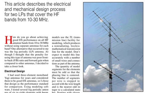 This QST article describes the electrical and mechanical design process for two LPs that cover the HF bands from 10-30 MHz
 -
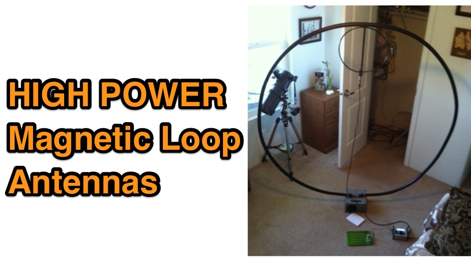 Magnetic Loop Antennas for The Radio Operator with Limited Space, a two part series of articles on how to construct a magnetic loop antenna, including directions on selecting high voltage tuning capacitor
 -
 Ten essential tips and truisms for understanding HF antenna: Non-resonant wire dipole antennas fed with open-wire line and an antenna tuner can function effectively as multiband antennas, as detailed in "The Classic Multiband Dipole Antenna" by WB8IMY in March 2004 QST. Coaxial cable, unlike balanced parallel-wire feed lines, can cause RF to travel on the outer shield braid, leading to RF feedback to the station; a 1:1 balun at the dipole center can mitigate this by isolating the unbalanced coaxial feed line. Antenna gain is achieved by shaping and directing RF energy, with beam antennas concentrating power in a specific direction, and wire antennas also exhibiting shaped radiation patterns. An antenna tuner's primary role is to match the transceiver's 50-ohm output to the antenna system's impedance, allowing modern transceivers to deliver full power. Wire antennas do not always require center feeding; end-fed long wires or off-center-fed dipoles (like the Windom) can be used, though they often necessitate an antenna tuner and a counterpoise or radial network. Dipole antennas do not need to be perfectly horizontal; their legs can be bent or inclined, which affects feed point impedance and may require SWR experimentation with coaxial feed. Vertical antennas shorter than a half wavelength require an efficient ground system, typically comprising elevated or buried radial wires, with more radials generally leading to better efficiency. A 1:1 SWR indicates an impedance match but does not guarantee antenna efficiency; an inefficient vertical antenna with a poor ground system can show a low SWR while wasting most RF as heat. Investing in high-quality, low-loss feed line, especially coaxial cable, is crucial for maximizing RF signal transfer and overall antenna system performance.
 -
 Specialize in engineering, design and repair of all rf equipment. Dealer for two way radios, scanners, shortwave radios, wi-fi antennas, wifi amplifiers. Based in Fortuna, California.
 -
 Supplier of two-way radio products and accessories to large and small businesses, volunteer groups, radio amateurs and individuals. Transceivers, receivers, antennas cw keys based in London UK
 -
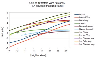 The article presents a detailed examination of 40-meter wire antenna performance, specifically focusing on the impact of antenna height on gain and radiation patterns. It quantifies how a 40-meter dipole at 1/8 wavelength above ground exhibits a high-angle radiation pattern, while raising it to 1/2 wavelength significantly lowers the take-off angle, improving DX capabilities. The author, VE3VN, leverages _EZNEC_ simulations to illustrate these changes, providing visual representations of the antenna's lobe structure at different elevations. Comparing a single dipole to a two-element wire array, the analysis shows that a 2-element array at 1/4 wavelength height can achieve **3.7 dBd** gain, outperforming a single dipole at the same height. This gain is further enhanced to **5.7 dBd** when the 2-element array is elevated to 1/2 wavelength, demonstrating the practical benefits of optimizing both element count and height for improved signal strength and directivity on the 40-meter band. The findings offer practical insights for hams seeking to optimize their wire antenna installations.
 -
 This is about Small Antenna types and their properties which can help choosing proper antenna for high-frequency wireless communications as: two-way radio, microwave short links, repeaters, radio beacons or wireless telemetry
 -
 Mounting antenna close each other. Distance calculations and tips on setting up antennas by KB9VBR
 -
 This resource details the construction of a Moxon rectangle antenna, a two-element wire beam, drawing inspiration from a _QST_ article by Allen Baker, KG4JJH, and a project group led by KD6WD. It outlines the use of _AC6LA_ software for critical measurements (A-E) to design the antenna for specific bands like 17 meters, emphasizing the simplicity of adjusting frequency and wire size. The guide covers material selection for spreaders, such as telescoping fiberglass fishing poles, and various hub constructions, including aluminum tubing and PVC joints, with accompanying images. The author shares practical insights from building multiple Moxons for 10, 15, 17, and 20 meters, noting consistent 1:1 SWR at design frequencies and broadbanded performance. It describes the feedpoint assembly using a 1:1 Yagi current balun and wire nuts for robust, adjustable connections. The resource also discusses element insulators made from Lucite strips and attachment methods to spreaders using plastic wire ties and duct tape, ensuring precise element spacing. Performance observations include significant signal improvements (4-5 S units) over quad loops and a unique "DX-Vane" effect where the suspended antenna self-aligns with the strongest DX signal. The author also recounts an unsuccessful attempt at a dual-band 17/20 meter Moxon, concluding that the Moxon is inherently a monoband antenna, supported by _EZNEC_ plots for a 17-meter design.
 -
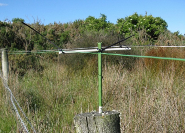 How do two-wire reversible direction Beverages work, an excellent document that explains fundamentals of beverage antennas. This article details the design and performance of a reversible beverage antenna. Leveraging orthogonality between common mode and differential mode currents on a 2-wire line, this antenna facilitates independent reception from both ends. While common mode signals arrive and are summed on a transformer's secondary for common mode reception, differential mode signals induce anti-phase currents, providing individual reception. Various measurements explore impedance, transmission loss, and F/B ratio, highlighting the antenna's effectiveness and areas for improvement. Notably, increasing the antenna's height significantly improved performance.
 -
 Operating a ham station often involves encountering radio frequency interference (RFI), RF feedback, or RF burns, which are frequently misattributed to poor equipment grounding. This resource meticulously dissects these assumptions, asserting that RF grounds on the operating desk often merely mask more significant system flaws. It identifies five primary causes for RF problems, including antenna system design flaws, proximity of the antenna to the operating position, DC power supply ground loops, equipment design defects, and poorly installed connectors or defective cables. The content emphasizes that issues like "hot cabinets" or changes in SWR when connecting a ground indicate substantial RF flowing over wiring or cabinets, a phenomenon known as common-mode current. The article provides detailed explanations of common-mode current generation, particularly from single-wire fed antennas like longwires, random wires, and OCF dipoles, which inherently present high levels of RF in the shack. It also illustrates how vertical antennas, lacking a perfect ground system, can excite feed lines with significant common-mode current. Through simulations, the author demonstrates how a dipole without a proper _balun_ can cause RF problems at the operating desk, showing current patterns and voltage distributions on feed line shields. The discussion extends to the proper application of _RF isolators_ and _ferrite beads_, clarifying their role in modifying common-mode impedance on cable shields and cautioning against their use as a band-aid for fundamental system defects. The resource advocates for correcting the actual source of RF problems, such as antenna system issues or poor connector mounting, rather than relying on internal shack grounding or isolators. It highlights that properly functioning two-conductor feed lines, like coaxial or open-wire lines, should result in minimal RF levels at the operating position, even without a desk RF ground. The author shares personal experience, noting that his stations since the late 1970s have operated without RF grounds at the desks, relying instead on proper antenna system design and feed line integrity.
 -
 Constructing a compact directional antenna for the 17-meter band, this resource details the build process for a Moxon rectangle, a two-element Yagi variant with folded-back elements. It covers the antenna's evolution from the _VK2ABQ beam_ and provides specific dimensions for a version built using fishing pole whips. The content includes a discussion of the antenna's radiation pattern, feedpoint impedance, and its inherent front-to-back ratio, which is often superior to a standard two-element Yagi. Practical considerations for element spacing and material choices are also addressed, alongside a visual representation of the antenna's physical layout. Performance data presented includes a comparison showing the Moxon rectangle's **2.5 dB gain** over a half-wave dipole and a front-to-back ratio of **20 dB**. The resource also touches upon the antenna's relatively wide bandwidth for a two-element beam and its suitability for portable operations due to its compact footprint. It offers insights into optimizing the design for specific operating conditions and discusses the advantages of its lower take-off angle compared to omnidirectional wire antennas, making it effective for DX contacts on the 17-meter band.
 -
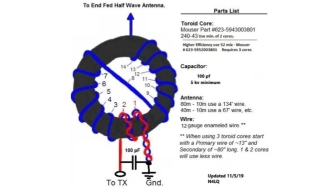 1:49 UNUN using two stacked FT240-43 cores for end fed halfwave antenna. To match the end fed half wave antenna to the coaxial feeder, it is necessary to have a matching network or transmission line transformer.
 -
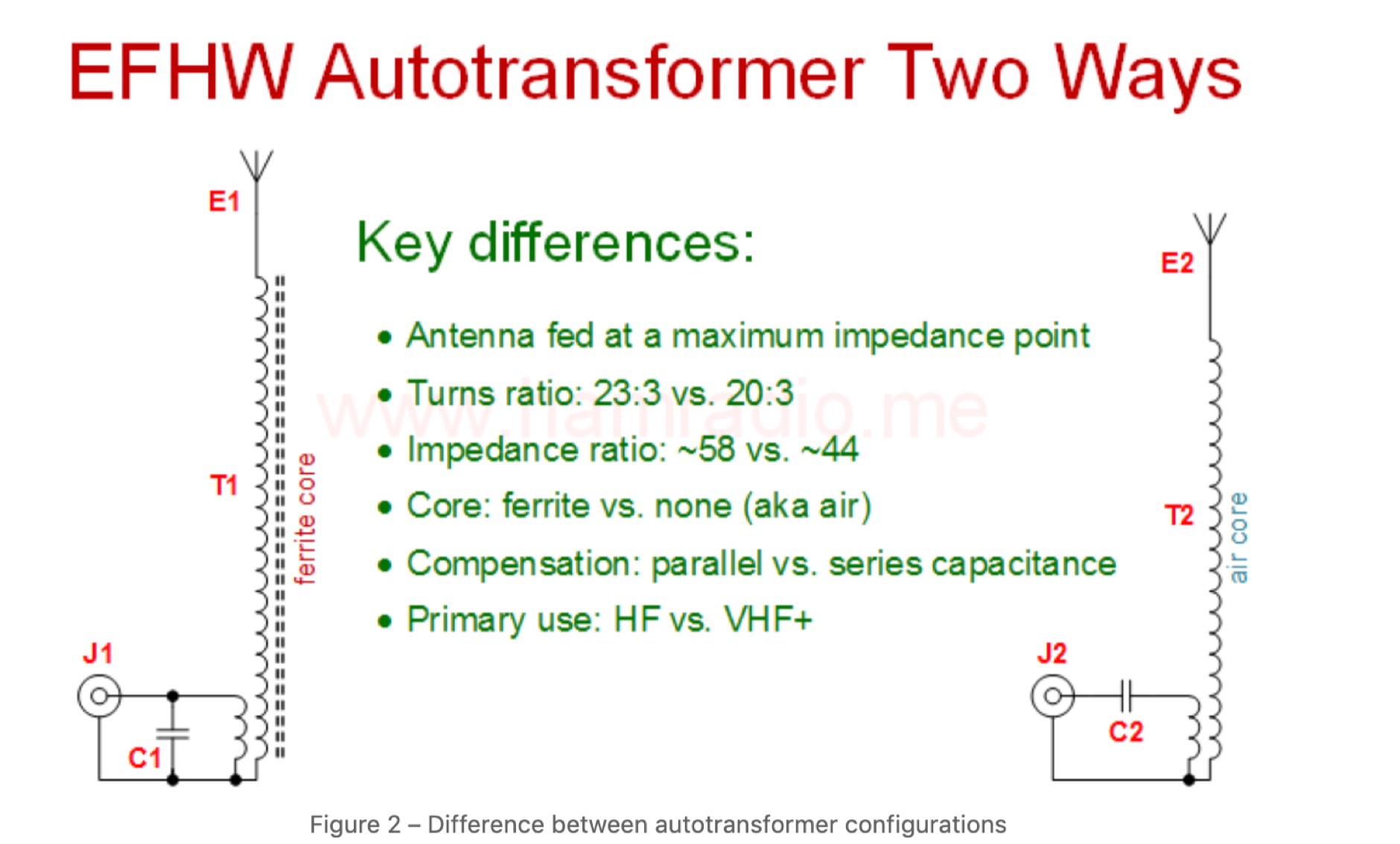 Two different ways to create autotransformer for end fed half wave wire antennas, by using ferrite or air core.
 -
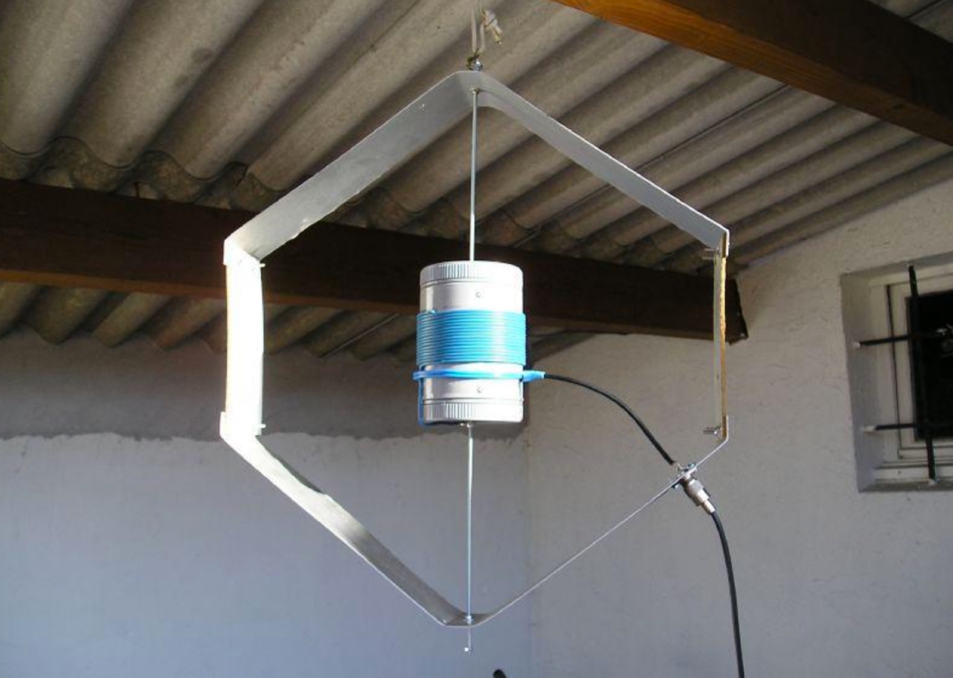 Isotron antennas are antennas of reduced size, without tuning. On 40 and 80m band, it is made of two plates into v whose angles are connected by a coil. In this article the description of a home made realization for the 40m band.
 -
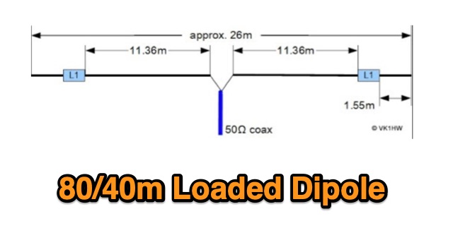 A dual band dipole antenna for 40 and 80 meters band. Total lenght of 26 meters, foreseen two coils at aprox 11 meters distance from center feed.
 -
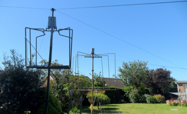 This article describes the development of two tunable antennas each consisting of three interconnected small loops and capable of providing excellent DX performance. The aerials are home-constructed, and located in a very small garden with a minimum of visual impact on the neighbours and are low enough in height to avoid the attention of UK planning authorities.
 -
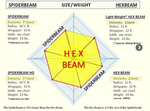 Differences of Hex Beam and Spiderbeam antennas designs, performance and measurements, rotor considerations when using this two kind of antennas
 -
 Constructing a dip oscillator provides radio amateurs with a fundamental piece of test equipment for resonant circuit analysis. This particular design, adapted by VK3YE from a concept by _Drew Diamond VK3XU_, details a practical build using readily available components. The unit incorporates four plug-in coils, covering a frequency range from **2.6 MHz to 55 MHz**, mounted on 5-pin DIN plugs for versatility. A salvaged two-gang air dielectric variable capacitor, fitted with a vernier reduction drive, serves as the tuning mechanism, with the smaller gang optimizing bandspread at higher frequencies. In practical application, the dip oscillator is used by setting the meter needle to approximately two-thirds scale. When the instrument's coil is brought near a tuned circuit under test, a noticeable dip in the meter reading indicates resonance. This allows for precise measurement of resonant frequencies in antennas, filters, and other RF circuitry, proving invaluable for homebrewing and troubleshooting. The design emphasizes short wire runs for stable operation, particularly at the higher end of its operational range.
 -
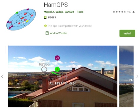 Display your current Maidenhead locator with 10 digit precision. It also computes bearing and distance to a set of target locations using locator or latitude / longitude. Useful to align antennas in VHF / UHF / microwave DX activities. No network or fancy maps usage, so it can be used even in remote locations.
 -
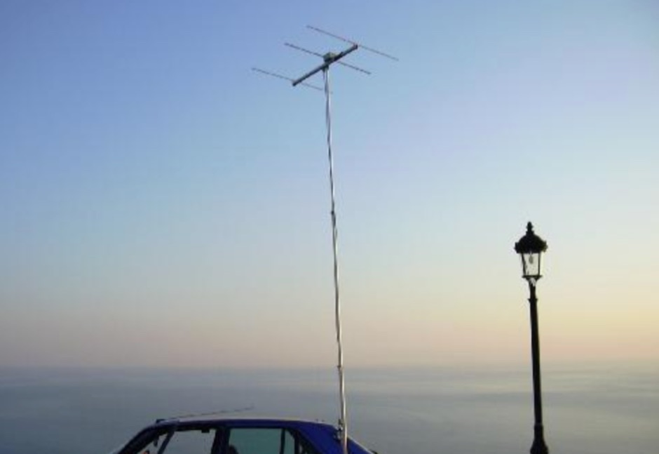 A great and efficient monoband VHF portable antenna. The article consist of two version of a 12.5 Ohm 3 elements yagi beam antenna plans for the two meter band, a full sized and a shortened version expecially designed for the SSB and CW on 144 MHz.
 -
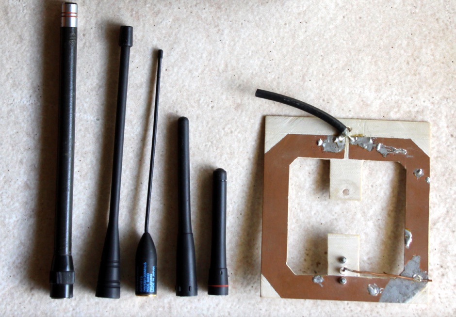 In this article the author analyze six different type of VHF handheld antennas and as result of his self training on his new vector network analyzer published this interesting report
 -
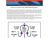 50 Ohm Coax Antenna Power Splitter and Matching Network
 -
 Designing and constructing a two-element receiving loop antenna array for HF operation involves specific considerations for achieving high directivity and noise reduction. This resource details a homebrew system comprising two 30-inch diamond-shaped loops, spaced 20 feet apart, which are fed through mast-mounted preamplifiers and passive signal combiners. The operational principle relies on adjusting phase delays between elements via precise _Belden 8241_ coaxial cable lengths, optimized for specific bands from 160m to 20m. Performance data, derived from _EZ-NEC_ modeling, illustrates consistent 90° azimuth-plane beamwidth and low take-off angles across the target bands, with _Receiving Directivity Factor_ (RDF) values comparable to a 300-foot Beverage antenna. The article presents detailed elevation and azimuth plots for 20m, 30m, 40m, 80m, and 160m, demonstrating the array's ability to provide strong response at low DX angles while also supporting _NVIS_ signals. Key components like the _DX Engineering RPA-1_ preamplifier and _DXE RSC-2_ signal combiner are discussed, alongside the importance of impedance matching to preserve antenna patterns. The construction emphasizes self-contained elements that do not require ground radials, offering a compact solution suitable for suburban environments and stealth installations, with a focus on optimizing receive performance independently from transmit antennas.
 -
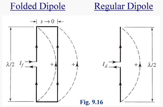 A folded dipole is an antenna, with two conductors connected on both sides, and folded to form a cylindrical closed shape, to which feed is given at the center.
 -
 Multi-Polarized antennas for Land Mobile Radio, Indoor & Outdoor Networks, Home Wireless, Mining Communications, Remote Monitoring, HAM & Scanner, Cellular, WiFi, Wimax, M2M, GPS, LTE, and GSM.
 -
 Details Amphenol's extensive product line, encompassing electrical, electronic, and fiber optic connectors, alongside coaxial and flat-ribbon cable solutions. The company designs, manufactures, and markets these interconnect systems globally, serving various communication network requirements. Their offerings support end-to-end connectivity, crucial for modern broadband infrastructure. Emphasizes the company's role as a major provider of components vital for reliable signal transmission in diverse applications. Products like _LMR(R) coaxial cables_ and various _RF connectors_ are essential for amateur radio installations, ensuring low loss and robust connections for antennas and transceivers. The focus on high-performance interconnects directly benefits hams constructing or upgrading their stations. Amphenol's broad portfolio includes specialized connectors and cable assemblies, meeting rigorous technical specifications for both commercial and amateur radio use.
 -
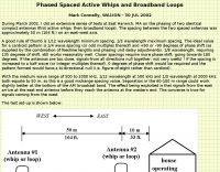 Phased Spaced Active Whips and Broadband Loops by WA1ION
 -
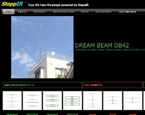 Presents _Beam Quest_, the official Japanese distributor for _SteppIR_ antennas, detailing their product lineup and services. The site showcases various _SteppIR_ Yagi models, including the _Dream Beam_ series (DB42, DB36, DB18E, DB11) with configurations from two to four elements, alongside the _Big IR_ and _Small IR_ vertical antennas. It also lists accessories such as TX/RX and PC interfaces, essential for integrating these advanced antenna systems into a ham shack. Operators often seek out _SteppIR_ antennas for their dynamically adjustable element lengths, which allow for optimization across multiple bands, a significant advantage for DXing and contesting. This adaptability contrasts sharply with fixed-element Yagis, providing a distinct edge in varying band conditions. The resource provides contact information, including email and phone numbers, for inquiries and support regarding _SteppIR_ products within Japan, serving as a direct point of contact for sales and technical assistance.
 -
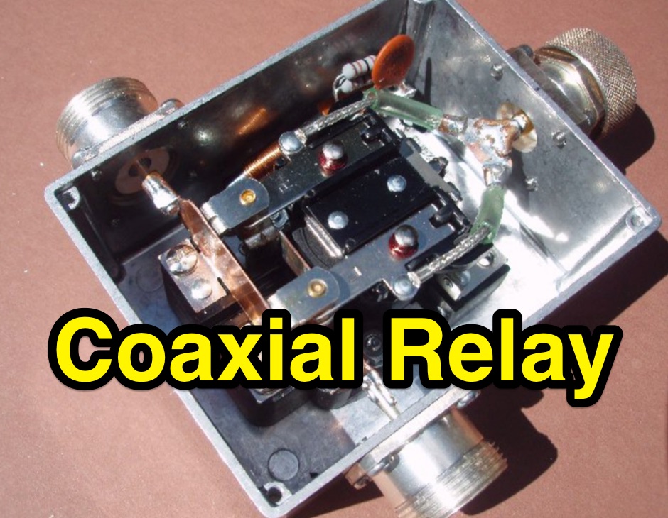 Build a SPDT coaxial relay that can be used as a main Transmit/Receive relay or an A-B switch to select between two different 6m antennas
 -
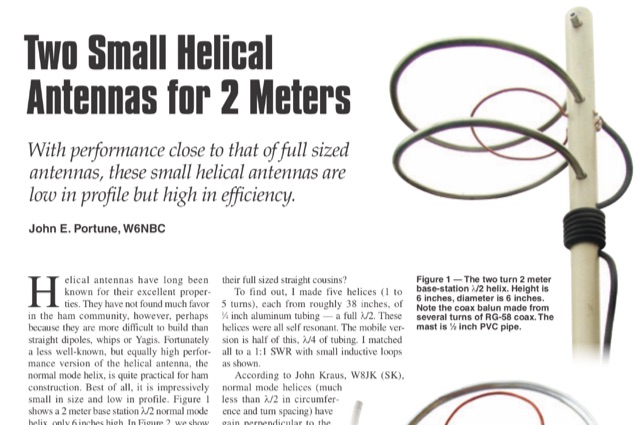 This article is about two excellent small helical antennas for the two meters band. With performance close to that of full sized antennas, these small helical antennas are low in profile but high in efficiency.
 -
-
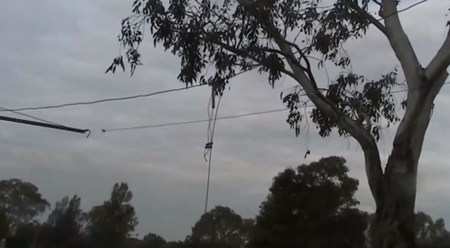 A page with an embedded video about a two elements yagi antenna for 28 MHz based on the original antenna design by VE7CA
 -
 In this post by N6CTA, discover the conversion of the Yaesu ATAS-120A screwdriver antenna for portable use. The author details the creation of two sets of radials, 16 and 32 in 16ft lengths, aiming to optimize the efficiency of ground-mounted antennas. Additionally, insights are shared on attaching male quick disconnect blade tabs, with potential plans for a radial plate kit.
 -
 Operating an amateur radio club, VE2CEV details its activities, including regular meetings and a significant project involving the construction of a **satellite ground station**. The resource outlines the project's inception, team formation, equipment acquisition, and the physical installation of antennas and rotator systems. It specifically mentions the use of a dual-axis AZ/EL rotator and antennas for VHF, UHF, and SHF (2 meters, 70 centimeters, and 13 centimeters), along with the strategic use of **Heliax cables** to minimize RF signal loss. The club also provides information on its interconnected repeater network covering southwestern Montérégie. The content highlights the practical application of the satellite station for communicating via amateur satellites and the International Space Station (ISS). It details the collaborative effort of members in securing a powerful Linux server, negotiating antenna installation with local authorities, and the precise alignment of antennas. The club emphasizes its role in guiding new amateurs, offering demonstrations, and potentially organizing courses, indicating a focus on community engagement and technical education within the amateur radio hobby.
 -
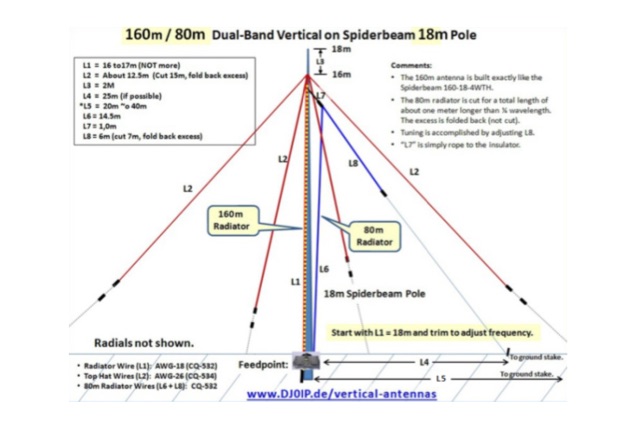 A dual band vertical antenna for 160 and 80 meters band, on a 18m spiderbeam fiberglass pole. This vertical is a good compromise when you want good performance on these two low ham bands and don't have the space to install two seperate antennas.
 -
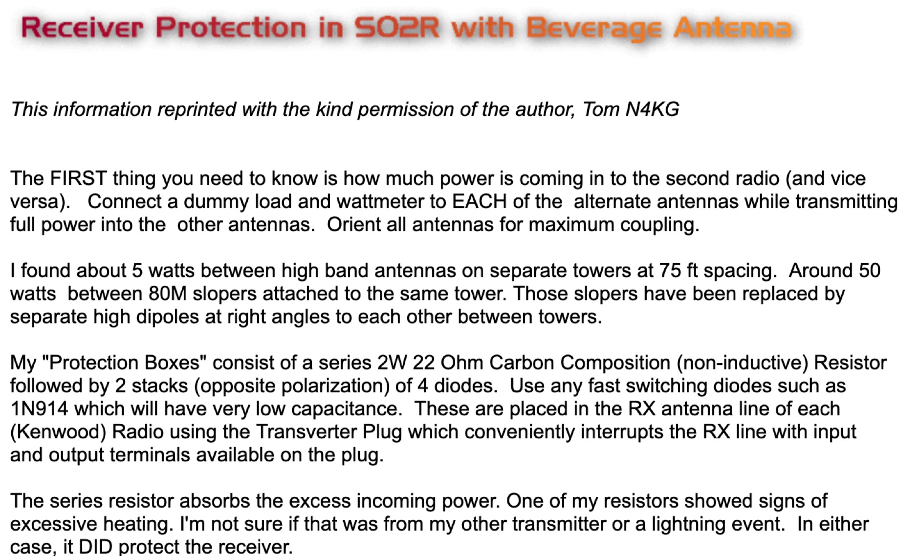 Operating in a Single Operator Two Radios (SO2R) setup, especially with beverage antennas, often exposes the receiving radio's front-end to significant RF energy from the transmitting radio. This resource details a practical, homebrew receiver protection circuit designed to mitigate this risk. The core of the design involves a non-inductive 2W 22 Ohm carbon composition resistor in series with the RX antenna line, followed by two stacks of four fast-switching diodes (e.g., _1N914_) configured in opposite polarizations. This arrangement effectively clamps the incoming voltage to approximately 2.8 V peak-to-peak, safeguarding sensitive receiver input components. The series resistor plays a crucial role by absorbing excess power, preventing the diodes from exceeding their current ratings and potentially failing open, which would leave the receiver unprotected. The author, _N4KG_, measured up to 50 watts of coupled power between 80M slopers on the same tower, highlighting the necessity of such protection. The design is presented as a cost-effective solution to prevent damage to receiver input transformers, with the author noting successful protection of a receiver even after a resistor showed signs of overheating. This simple circuit can be integrated via a transverter plug, offering a robust defense against high RF input.
 -
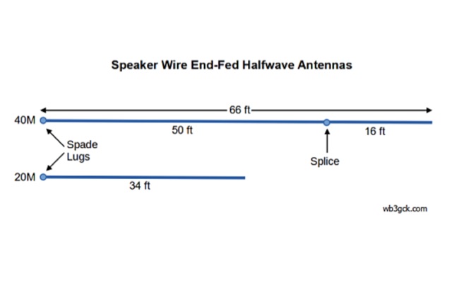 Author experiments end fed half wave antennas using common two conductore speaker wire, this article features a couple of end-fed halfwave wires for the 40M and 20M bands.
 -
 High Speed Multimedia (HSMM) radio, as introduced by John Champa, K8OCL, represents a significant advancement in amateur radio's digital capabilities, moving beyond traditional keyboard modes like packet radio. This initiative, driven by ARRL's Technology Task Force, focuses on developing high-speed digital radio networks capable of up to 20 megabits per second. HSMM primarily facilitates digital voice (DV) and digital video (ADV), enabling real-time video transmission from emergency scenes to an EOC without expensive ATV gear, often requiring only a laptop, a PCMCIA card, a digital camera, and a small antenna. The working group's initial efforts concentrate on cultivating microwave skills within the amateur community to build and support portable and fixed high-speed radio-based local networking, or **RLANs**. These networks prove invaluable for RACES and ARES organizations, as well as homeland security and other emergency communications. Field Day exercises and simulated emergency tests (SETs) are encouraged to hone skills in rapid site surveys and deploying broadband HSMM microwave radio networks, with examples like linking Field Day logging stations or antenna test results at the Midwest VHF-UHF Society Picnic 2003. Getting started with HSMM often involves adapting off-the-shelf **IEEE 802.11** (WiFi) equipment to comply with amateur radio regulations, typically operating in the 2.4 GHz ISM bands. While consumer WiFi gear has range limitations under Part 15 rules, proper setup under amateur regulations can extend coverage significantly, with test networks like the Hinternet achieving 5-15 mile ranges at 54 M bit/s using small mast-mounted dish antennas. Careful selection of equipment with external antenna ports, high transmit power, and low receive sensitivity is crucial, along with using low-loss coaxial cable like LMR-400 for optimal performance at these frequencies.
 -
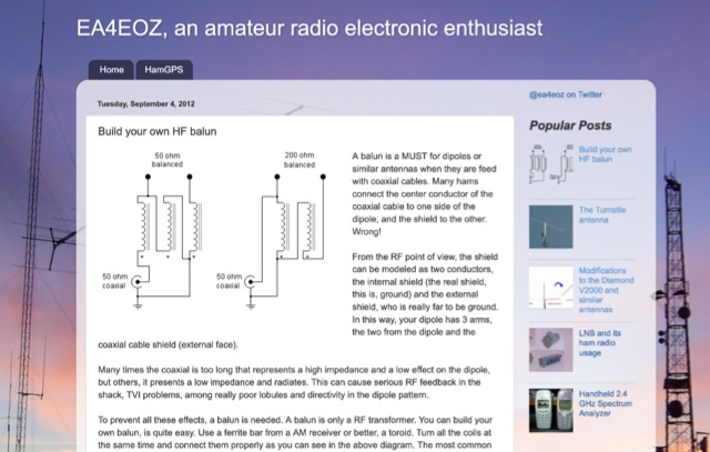 A balun is a MUST for dipoles or similar antennas when they are feed with coaxial cable. From the RF point of view, the shield can be modeled as two conductors, the internal shield (the real shield, this is, ground) and the external shield, who is really far to be ground. In this way, your dipole has 3 arms, the two from the dipole and the coaxial cable shield (external face)
 -
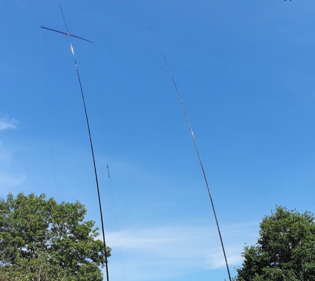 On the field comparison among C-Pole antenna, an EFHW vertical antenna and an Inverter V dipole antenna. Test is done using two identical WSPRLite beacons that transmit with 200mW on the WSPR frequency and analyzing spotted results.
 -
 DL7JV shares his practical experience building and testing capacitive antennas, initially skeptical of their performance compared to magnetic loops and mono-band dipoles. His interest was piqued after hearing a Spanish station running 100 Watts on 80 meters with a 1-meter Micro Vert, making DX contacts into PY and UA0, despite the antenna being only 4 meters high in a garden. This prompted DL7JV to investigate further, consulting resources from DL7PE and DL7AHW, the latter providing DOS programs like "Mitspule.exe" and "Spulenprg.zip" for calculating antenna dimensions and coil conversions. The article outlines the construction of two prototype antennas: one for 7.050 MHz using a 75mm PVC pipe and another for 3.550 MHz with a 110mm PVC pipe. Both designs feature aluminum foil condensers and coils wound from 1mm² H07V-K wire. DL7JV provides specific measurements for the condenser capacitance, surface area, diameter, height, coil inductance, turns, and wire length for both 40m and 80m versions, along with RG58 feedline lengths. Initial reception tests for the 7 MHz antenna, placed indoors, yielded impressive S9+5 signals from a German station compared to an S8 from a 42-meter roof-mounted loop, even hearing a Japanese station. Transmission attempts on April 4, 2004, despite moderate solar storm conditions, resulted in successful QSOs on 7 MHz with EA5OT (579/559) and on 3.5 MHz with YT1NT (579/559) and G4KKI (579/559) using 100 Watts. DL7JV notes the antenna's sensitivity to coordination and feedline layout, suggesting a modification from DL7AXO involving a 500pF fixed capacitor and coil tap for improved SWR stability. He concludes that while the capacitive antenna is space-saving and performs well for reception and 100W transmission indoors, its transmit performance doesn't yet match larger antennas, with further outdoor field tests planned. DL7JV also intends to build a 1.8 MHz version.
 -
 Design and manufacture antennas for mobile devices, wireless data including WiMAX, WiFi, and WISP (Wireless Internet), two-way radio and RFID (Radio Frequency Identification).
 -
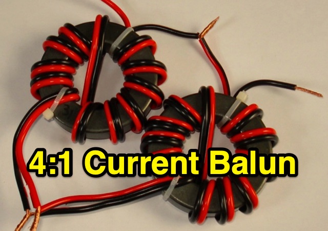 This blog post details the construction and usage of a 4:1 current balun, using two FT240-31 ferrite cores and 12 bifilar turns. It clarifies common misconceptions about using 4:1 baluns with G5RV antennas and ladder-line to coaxial cable connections. M0PZT emphasizes the importance of proper measurements and the limitations of internal baluns in manual antenna tuners. Detailed instructions and considerations for winding and deploying the balun are provided, along with advice on choosing suitable cores and wire for various power levels and frequency ranges.
 -
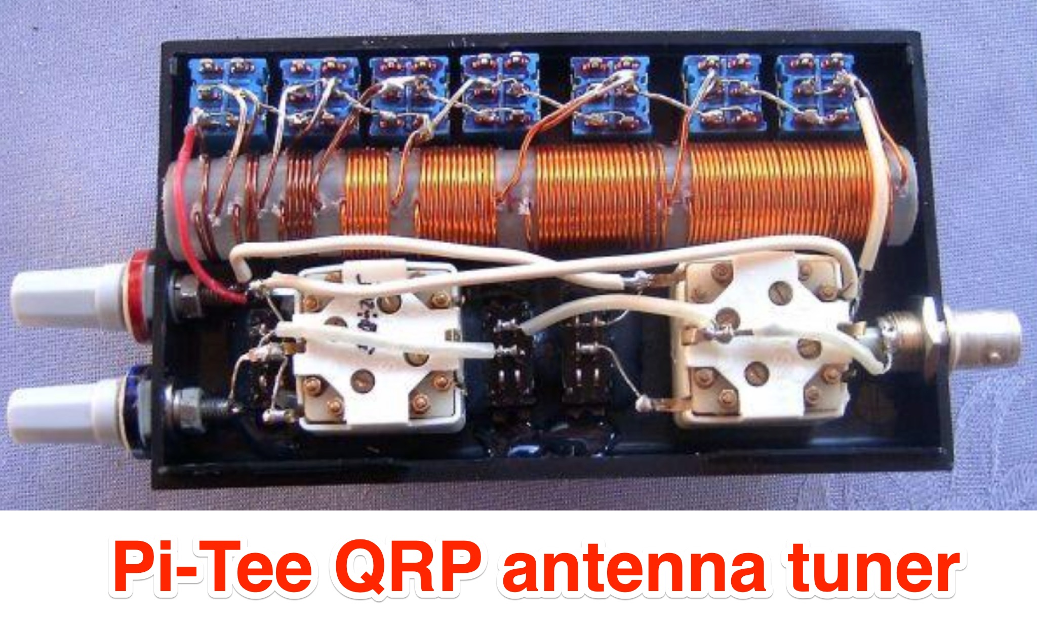 LZ1AQ describes a versatile QRP antenna tuner that switches between Pi and Tee configurations with a single toggle. Using two variable capacitors and a seven-switch stepped inductor providing 128 increments (0.16 to 18.7 uH), this compact design handles 3.5 to 28 MHz with excellent matching range. The Pi mode works best for certain impedances while Tee mode proves more universal, matching loads the Pi cannot. Built in a plastic enclosure using salvaged radio capacitors, the tuner operates reliably up to 100 watts with proper antennas, though it's optimized for QRP service with random wires.
 -
 Steve Nichols, G0KYA, presents a practical examination of ground systems for vertical antennas, drawing heavily on the empirical research of Rudy Severns, N6LF. He explains that a robust radial field is crucial for ground-dependent verticals, effectively replacing the antenna's "missing half" and mitigating severe RF absorption in lossy soil. Nichols clarifies that surface radials do not strictly require a quarter-wavelength; instead, deploying a minimum of 16 to 32 shorter wires often yields superior results compared to fewer, longer ones. The presentation also addresses the common SWR paradox: a poor ground might show a perfect 1:1 match, but adding radials, while potentially raising the SWR to around 1.4:1, significantly improves true radiation efficiency. Nichols defines counterpoises as elevated wire networks that substitute for earth connections, offering solutions for limited-space installations, such as the **Folded Counterpoise (FCP)** for 160 meters. This resource provides actionable engineering data for optimizing vertical antenna performance.
 -
 This page by Keith Greiner describes a magnetic loop antenna project, providing step-by-step instructions to create two versions of a system with one large loop and one small loop. It includes details on how to construct the loops using different materials, along with the necessary equipment like antenna analyzers, tuners, and software. The page is divided into five sections covering project discussion, design summary, an improved small loop, construction steps, and radiation pattern analysis. Aimed at hams interested in building their own magnetic loop antennas, the page offers practical guidance and insights into impedance matching for improved performance.
 -
 Dipole for 40m band. It is a simple linear loaded dipole feeded with 450-Ohm openwire feedline. Designed it for resonance at 7.050 MHz, can be tuned on 30m and 80m bands with an external antenna tuner. Build with simple electrical copper wire (2.5 mmq/13 awg) and two fishing poles with size of about 7 m/23 ft.
 -
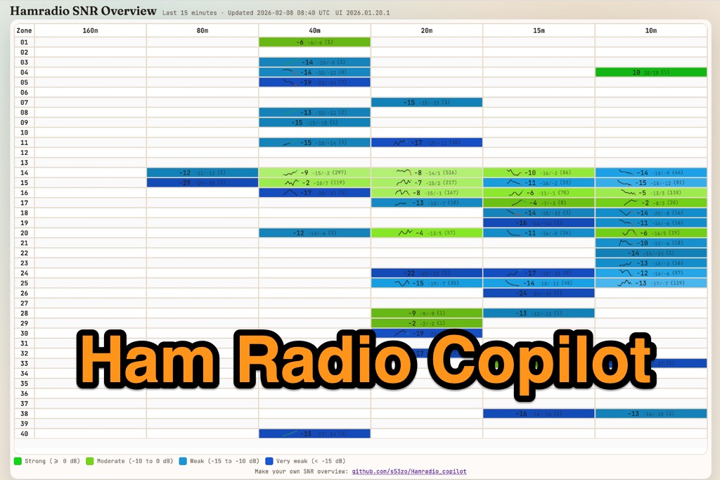 Hamradio_copilot is an open-source tool designed for DXers and contesters who need real-time situational awareness. It is ideal for operators who want to visualize propagation trends instantly rather than scrolling through raw text streams of cluster spots. Rally acting as a copilot for your station, this tool transforms raw data into actionable intelligence. By visualizing Signal-to-Noise Ratios (SNR) across different bands, it helps operators make quick decisions on which band to prioritize or where to point their antennas, effectively showing not just who is on air, but where the propagation is currently open from your location. This is a fantastic information for avid contesters. The software aggregates data from two primary services: - Reverse Beacon Network (RBN) via Telnet. - PSK Reporter via MQTT feeds. It processes this data to generate a comprehensive HTML report featuring SNR heatmaps and statistical breakdowns by ITU Zone. Users can filter data by specific zones or country codes (ADIF), analyze historic time ranges, and optionally integrate solar weather data. The complete source code is available on GitHub, allowing for community customization. It is written in Python and uses SQLite for data management.
 -
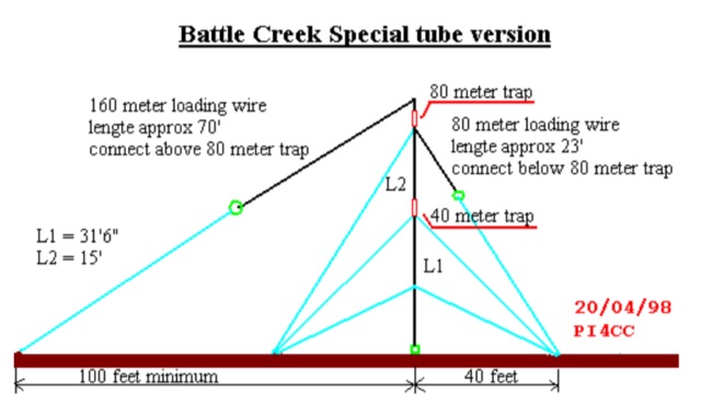 This antenna is designed for 40, 80 and 160 meters to complement a tri-band beam normally taken on DX peditions for 10, 15 and 20 meters, so six bands can be worked with only two antennas.