Search results
Query: circuit
Links: 338 | Categories: 14
Categories
- Software > Circuit Design
- Technical Reference > Batteries
- Technical Reference > Batteries > Battery Charger
- Technical Reference > Electronics
- Manufacturers > Test Equipment > Impedance Analyzers
- Technical Reference > Morse Code Oscillator
- Technical Reference > Test Equipment > Multimeter
- Software > PCB Design
- Technical Reference > Receiver Front-End Protector
- Software > RF Design
- Technical Reference > Soldering and Desoldering
- Technical Reference > Transverters
- Technical Reference > Vacuum tube
- Software > Vector Network Analyzer
-
 The digital wattmeter project was created for the purpose of measuring power in the range of 300nw to 30w.
 -
 Qucs, briefly for Quite Universal Circuit Simulator, is an integrated circuit simulator which means you are able to setup a circuit with a graphical user interface (GUI) and simulate the large-signal, small-signal and noise behaviour of the circuit. After that simulation has finished you can view the simulation results on a presentation page or window. Run on Linux.
 -
 Simple circuit, with a simple push, transmit a memorized Cw messages
 -
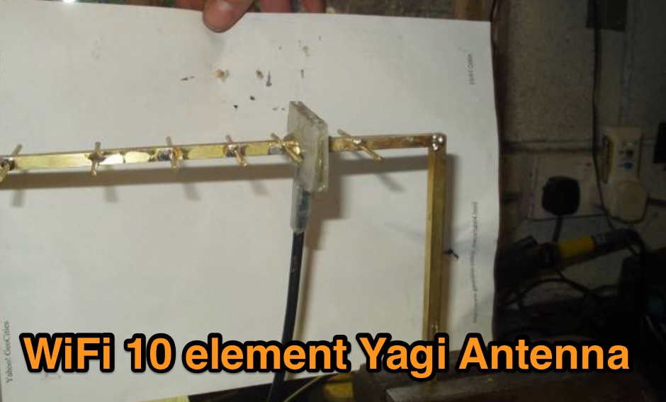 A DIY project of a WiFi 10 elements Yagi antenna
 -
 This circuit consists of microphone amplifier and a high pass filter. Suitable to improve signal readability.
 -
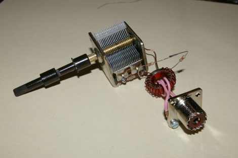 An easy to deploy antenna, commonly considered the best solution for portable operations. Thir article includes a simple LC parallel circuit to match the impedance by IW7EHC
 -
 A rotator modification by W4ZT
 -

-
 DigChip is a provider of integrated circuits documentation search engine, it's also distributor agent between buyers and distributors excess inventory stock.
 -
 For amateur radio operators engaged in **radio direction finding** (RDF) and **transmitter hunting** (T-hunting) activities, this resource provides a catalog of printed circuit boards (PCBs) for constructing various DF and foxhunt-related projects. The offerings include PCBs for 80-meter fox transmitters and receivers, UHF fox transmitters with audio recording capabilities, and several designs for general-purpose radio direction finders. Specific projects like the "Simple 80M ATX-80 Transmitter" and the "N0GSG DSP Radio Direction Finder" are listed, along with attenuator boxes and specialized components for Doppler DF systems. The catalog details PCBs for projects published in prominent amateur radio magazines such as *73's*, *CQ*, *QST*, and *PE*, indicating their origin and design pedigree. For instance, the "Montreal Fox Controller" is sourced from the *Homing-In* column by Joe Moell, K0OV. The resource also lists components for advanced Doppler DF systems, including main boards, LED display boards, and antenna switch boards, with options for programmed PIC microcontrollers. Pricing for each PCB is provided, allowing hams to acquire the necessary components for their DIY RDF endeavors.
 -
 Ebook by Akira Matsuzawa Tokyo Institute of Technology, Building blocks in RF system and basic performances, Device characteristics in RF application , Low noise amplifier design, Mixer design and Oscillator design
 -
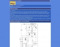
 A 4 AMP / 18V regulated power supply schematic, designed by _ON6MU_, provides a detailed circuit diagram for constructing a robust power source. The design focuses on delivering a stable 18-volt output at up to 4 amperes, crucial for powering various amateur radio equipment. This resource presents a clear visual representation of component interconnections, including rectifiers, filter capacitors, and voltage regulation stages, essential for DIY enthusiasts building their shack infrastructure. The schematic's clarity facilitates understanding the power flow and component roles within the circuit. This circuit design offers a practical solution for hams needing a reliable 18V supply, potentially useful for driving specific transceivers, amplifiers, or accessory circuits. While specific performance measurements or comparisons to other designs are not detailed, the schematic itself serves as a foundational blueprint. Builders can adapt or modify the _power supply_ to suit their particular needs, such as integrating overcurrent protection or fine-tuning the output voltage with adjustable regulators. The straightforward presentation makes it accessible for those with basic electronics knowledge to assemble and troubleshoot.
 -
 This simple and cost effective interface circuit is designed for use with any ICOM amateur radio equipment with CIV interface
 -
 Circuit Improvements and Maintenance Procedures for the TS-830S
 -
 Diplexer is a passive device, a special filter circuit that seperates 2 different bands, not to be confused with the duplexer that usually separate 2 different frequencies on the same band.
 -
 PIC Programmer software package that allows you to program all types of serial programmable Integrated Circuits using Windows 95/98/NT/2000/ME/XP
 -
 A simple simple sweep generator circuit design where the sawtooth is generated by the PNP transistor and a 555
 -
 This program intended for electronic circuit analysis (mainly for Linux). ViPEC is a powerful tool for the analysis of high frequency, linear electrical networks.
 -
 Operating on the 2200m band (135.7-137.8 kHz) often presents challenges for amateur radio transceivers, which typically exhibit poor receiver performance at these very low frequencies. This project addresses the issue by providing a design for a dedicated 137 kHz antenna preamplifier, specifically tailored to improve signal reception for radios such as the _Yaesu FT-817_. The preamplifier circuit utilizes a low-noise FET input stage, crucial for minimizing self-generated noise and maximizing the signal-to-noise ratio from weak LF signals. The design includes a detailed schematic, component values, and construction notes, enabling homebrewers to build a functional unit. The goal is to achieve significant gain, making the faint signals on 2200m more discernible and improving overall band usability. Key design considerations include impedance matching to typical antenna systems and ensuring stable operation across the narrow LF segment. The circuit aims for a **low noise figure** and sufficient amplification to overcome the inherent limitations of general-purpose HF transceivers when operating below **200 kHz**.
 -

-
 This Z-Match is a link coupled all-band tuner. Two all band tank circuits cover 3-14mhz and 14-30mhz. The tank output links are selected with a very heavy duty SPDT rotary switch.
 -

-
 The Elecraft K2 transceiver requires specific modifications for optimal soundcard digital mode operation, particularly for PSK31. The original article, circa 2001, details initial challenges with manual PTT and speech compression settings. A key modification involves adding headphone audio and a compression disable signal to the K2's microphone jack, utilizing pins 4 and 5. The **COMP0** signal, active low, is shorted to ground via a non-inverting open collector switch circuit, comprising two resistors and two transistors, mounted on the SSB board near U3. This circuit provides effective control of an analog signal line with good noise immunity. The switchbox itself repurposes a computer COM port switch, using only two of its original connectors and four of the nine poles. It integrates a microphone preamplifier, a PTT circuit built with 'flying leads' construction, and RCA jacks for soundcard connections. A trimpot adjusts the audio drive to the K2. The central DB9 connector links to the K2's mic connector via a shielded RS232 serial cable, ensuring proper grounding and signal routing. An external footswitch PTT jack is also included. Further enhancements include a **noise-canceling microphone** preamp based on a QST December 2000 article, adapted for Heil mic elements. This preamp, built with pseudo-Manhattan style construction, provides a gain of approximately 2 by changing emitter resistors (R9 and R16) from 680 ohms to 330 ohms. A 10-ohm series resistor and 47 µF capacitor on the +5V supply mitigate noise spikes.
 -
 The Remote Control Antenna Switch consists of two circuit boards. The control unit and the remotely controlled switch
 -
 This document details the design and construction of the PA70H, a 50-watt RF amplifier for the 70MHz (4-meter) amateur radio band. Built around the Mitsubishi RD70HVF1 MOSFET transistor, the amplifier delivers 45-55W output with 3-5W input power while operating on 13.8V DC at approximately 7-8A. The PCB design incorporates multiple protection circuits including overcurrent, SWR, and temperature control. The amplifier features various control modes including GND PTT, +13.8V PTT, and RF VOX. Two versions are available: PA70HLI (requiring 100mW input with additional driver) and PA70H (for 3-5W input). The comprehensive documentation includes circuit diagrams, assembly instructions, and performance data showing successful operation from both 100mW and 3.5W input sources.
 -
 A schematic for a DX circuit protection for the Yaesu FT-817, provides protection from the external power supply overvoltage by DL2LTO in german
 -
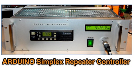 This project hereby presented is a complete HAM radio simplex 'smart' repeater, built around a Motorola GM-350/950, Arduino NANO board and a WINBOND audio recording integrated circuit
 -
 This circuit stores a single morse code message as bits in an EPROM chip, the message is sent to a relay which can key a CW transmitter.
 -
 Negative feedback is often referred to as shunt feedback in conjunction with emitter degeneration.
 -
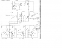
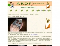 The 80m TX described here is the well known ON7YD ATX-80 and timer, combined and re-engineered to fit a readily available enclosure by G3ZOI
 -
-
 Demonstrates the construction of a custom programming cable for Yaesu VX-7R and VX-5R handheld transceivers, enabling computer interfacing for memory management and frequency coverage adjustments. The resource details a six-transistor circuit design, powered by the computer's RS232 interface, utilizing readily available and inexpensive discrete components. It includes a complete bill of materials, specifying transistors like the _2N2222_ and _2N3906_, diodes, and resistors, along with a matrix board layout for compact assembly within a 75x50x25mm enclosure. The guide provides practical tips for working with matrix board, such as scoring and snapping, track cleaning, and component soldering order. It outlines the specific connection requirements for both the VX-7R (via Yaesu's CT-91 breakout lead with a 2.5mm stereo jack) and the VX-5R (via CT-44 or a four-section jack), detailing signal and ground pinouts. The author successfully tested three circuits, documenting the one with complete two-way communication, allowing users to program their rigs with software like _VX-7 Commander_ and achieve capabilities beyond commercial cables, including band adjustments.
 -
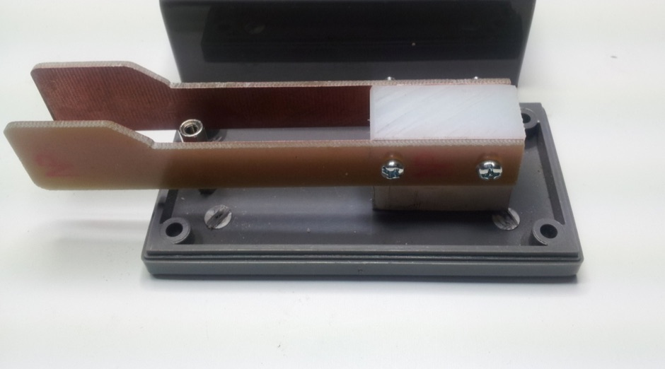 Home Made CW paddles made from a printed circuit board and a teflon mounting block while contacts are made with simple brass threaded rods.
 -
 A simple low-power broadcast-type circuit, using a crystal oscillator integrated circuit and an a collector modulated AM oscillator
 -
 1500 watts PEP output from a Kenwood TL-922 amplifier requires careful attention to parasitic suppression and component selection to ensure stability and longevity. This resource critically examines common modifications, often based on anecdotal evidence rather than sound engineering principles, that can degrade performance or introduce new issues. It highlights how replacing aged components often gets misattributed to the efficacy of unnecessary modifications, leading to widespread misinformation within the amateur radio community regarding amplifier stability. The article details specific, effective modifications for the TL-922, such as shortening anode-to-chassis and anode-to-grid paths to improve VHF stability and efficiency. It addresses issues like incorrect capacitor types in the tank circuit, inadequate grid grounding, and poor RF sheet metal design, providing practical solutions like adding direct ground connections for the plate tune variable capacitor. The author also discusses proper parasitic suppressor design, emphasizing the importance of lead length and component selection for optimal performance and harmonic suppression, contrasting these with less effective or detrimental 'magical suppression kits'.
 -
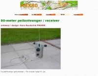 80-meter peilontvanger / receiver includes printed circuit sample and list of components
 -
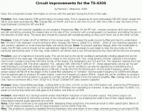
 A circuit for a 5 milliwatts super QRP morse code transceiver by VE2ZAZ
 -
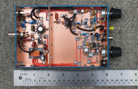
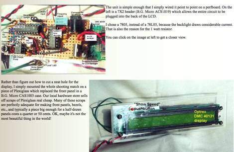
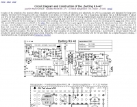 Circuit Diagram and Construction of the Bartling RX-40 Joachim Munch DF4ZS
 -
 A K9AY loop antenna project done with Far Circuits pc boards for the antenna switch and bandpass filter and preamp by K7SFN
 -
 A hombrew QRP transceiver for 40 meter band with many pictures, circuit and sound recording of some QSOs made with this Rig consisting of 5 transistor and one chip.
 -
 Protecting amateur radio equipment from transient overvoltages requires robust lightning and surge protection, which is the focus of Electronic Specialty Products. The company provides various devices, including coaxial lightning arrestors for antenna feedlines and surge protectors for AC power lines and data circuits. These devices are engineered to divert high-energy surges, such as those caused by direct or indirect lightning strikes, away from sensitive transceivers, amplifiers, and computer components, thereby preventing catastrophic damage. Key products include the _Coaxial Lightning Protector_ series, designed for various impedance levels and frequency ranges up to 3 GHz, and the _AC Line Surge Protector_ for shack power distribution. Effective deployment of these protection devices can significantly reduce the risk of equipment failure and ensure operational continuity during severe weather. For instance, a properly installed coaxial arrestor can handle peak currents of **20 kA**, while AC line protectors offer clamping voltages typically below 400V. Comparing different models reveals varying levels of insertion loss and return loss, with some coaxial units exhibiting less than 0.1 dB loss at 500 MHz, making them suitable for high-performance HF and VHF/UHF operations. Integrating these components into a comprehensive grounding system is crucial for achieving maximum protection against both common-mode and differential-mode surges.
 -
 This software package allows you to program all types of serial programmable Integrated Circuits using Windows 95/98/NT/2000/ME/XP
 -
 Edwin H. Armstrong's foundational contributions to radio technology are presented, including the _Regenerative Circuit_ (1912), the _Superheterodyne Circuit_ (1918), the Superregenerative Circuit (1922), and the complete FM System (1933). This resource functions as a curated collection of historical documents and artifacts, many previously uncirculated, stemming largely from the _Houck Collection_. The site's purpose is to offer these primary source materials for study and enjoyment, rather than to retell Armstrong's life story, which is covered in works like Lawrence Lessing's "Man of High Fidelity" and Tom Lewis's "Empire of the Air." The collection emphasizes original documents, photographs, and equipment, all sourced from the Houck Collection unless explicitly noted otherwise. The site is structured for browsing chronologically, by selected year, or by highlight, allowing users to explore Armstrong's technical evolution. Document files are intentionally large to preserve readability and detail, while individual pages are kept concise to optimize loading times. The content provides direct insight into the technical development of radio communications.
 -
 A PIC based morse code decoder circuit
 -
-
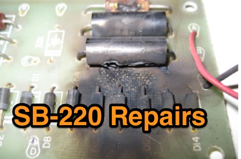 Heathkit SB 220 mods, replacing the Zener ZD1, replacing the plate-voltage voltage divider, adding a keying circuit for solid state transceivers
 -
 This almost trivial circuit may be used to charge a pair of AA or AAA sized rechargeable battery cells from sunlight.
 -
 Schematic of a homebrew receiver and keying
 -
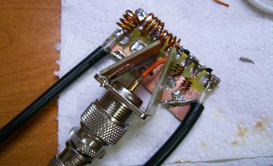
 This circuit enables fair copy of strong 444 MHz signals, off a local repeater, using a 2m rig and a 1/4λ 70 cm indoor ground plane antenna.
 -
 This is not a sophisticated automatic keyer but it is lot QRP to build and to have fun operatin