Search results
Query: dipole antennas
Links: 171 | Categories: 10
-
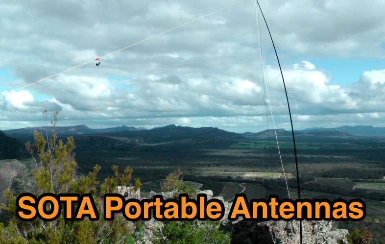 A review of some portable antennas for SOTA operations, including linked dipoles, end-fed, verticals
 -
 About windom antennas and OCF dipoles, tricks on covering more bands moving feed-points and potential problems. Problems caused by common mode currents in OCF dipoles
 -
 Operating a ham station often involves encountering radio frequency interference (RFI), RF feedback, or RF burns, which are frequently misattributed to poor equipment grounding. This resource meticulously dissects these assumptions, asserting that RF grounds on the operating desk often merely mask more significant system flaws. It identifies five primary causes for RF problems, including antenna system design flaws, proximity of the antenna to the operating position, DC power supply ground loops, equipment design defects, and poorly installed connectors or defective cables. The content emphasizes that issues like "hot cabinets" or changes in SWR when connecting a ground indicate substantial RF flowing over wiring or cabinets, a phenomenon known as common-mode current. The article provides detailed explanations of common-mode current generation, particularly from single-wire fed antennas like longwires, random wires, and OCF dipoles, which inherently present high levels of RF in the shack. It also illustrates how vertical antennas, lacking a perfect ground system, can excite feed lines with significant common-mode current. Through simulations, the author demonstrates how a dipole without a proper _balun_ can cause RF problems at the operating desk, showing current patterns and voltage distributions on feed line shields. The discussion extends to the proper application of _RF isolators_ and _ferrite beads_, clarifying their role in modifying common-mode impedance on cable shields and cautioning against their use as a band-aid for fundamental system defects. The resource advocates for correcting the actual source of RF problems, such as antenna system issues or poor connector mounting, rather than relying on internal shack grounding or isolators. It highlights that properly functioning two-conductor feed lines, like coaxial or open-wire lines, should result in minimal RF levels at the operating position, even without a desk RF ground. The author shares personal experience, noting that his stations since the late 1970s have operated without RF grounds at the desks, relying instead on proper antenna system design and feed line integrity.
 -
 A presentation of the Yagi Antennas, and other interesting tid-bits by Brian Mileshosky. The document provides an in-depth exploration of the Yagi-Uda antenna, detailing its historical development, design principles, and performance characteristics. Originally described in the 1920s, the Yagi antenna features a driven element and parasitic elements, including reflectors and directors, which collectively determine its behavior. The document highlights how element lengths, diameters, and spacing influence gain, impedance, and directivity. It also discusses the antenna's reciprocal nature and presents data on typical gain values for various element configurations. Additionally, the text covers practical considerations, such as the construction of a "Tape Measure Yagi" for amateur use, and touches on related antenna types like dipoles and their application in Near Vertical Incident Skywave (NVIS) communication.
 -
 US amateur radio antenna manufacturer. Produce baluns, delta loops, dipoles, ocf antennas and more
 -
 Constructing a compact directional antenna for the 17-meter band, this resource details the build process for a Moxon rectangle, a two-element Yagi variant with folded-back elements. It covers the antenna's evolution from the _VK2ABQ beam_ and provides specific dimensions for a version built using fishing pole whips. The content includes a discussion of the antenna's radiation pattern, feedpoint impedance, and its inherent front-to-back ratio, which is often superior to a standard two-element Yagi. Practical considerations for element spacing and material choices are also addressed, alongside a visual representation of the antenna's physical layout. Performance data presented includes a comparison showing the Moxon rectangle's **2.5 dB gain** over a half-wave dipole and a front-to-back ratio of **20 dB**. The resource also touches upon the antenna's relatively wide bandwidth for a two-element beam and its suitability for portable operations due to its compact footprint. It offers insights into optimizing the design for specific operating conditions and discusses the advantages of its lower take-off angle compared to omnidirectional wire antennas, making it effective for DX contacts on the 17-meter band.
 -
 The Superantennas MP-1 portable HF antenna is analyzed for its design and field performance, particularly its high-Q loading coil and 3/8-inch mounting. The review details the antenna's construction, including an 8-inch vertical section, a large-diameter loading coil tuned by a sleeve, and a 4-foot whip that disassembles into six rods for transport. Initial testing with the supplied 10-foot ribbon cable "ground plane" yielded poor SWR and RF hot conditions, indicating an inadequate ground system. Further experimentation with longer radials and resonant counterpoises for each band improved matching and eliminated RF hot issues, but introduced significant operational complexity. The author notes the difficulty in optimizing both counterpoise length and coil setting without an antenna analyzer, and the sensitivity of the MP-1 to counterpoise deployment. The review also discusses the recommendation to tune for maximum received signals rather than minimum SWR, often necessitating an external ATU due to the antenna's typical low impedance. The **MP-1**'s critical dependence on resonant counterpoises for effective operation, especially when elevated, is highlighted as a major drawback for portable use. The author ultimately sold the antenna, concluding that despite its sound technical design, its fussy nature and the need for extensive counterpoise management or an ATU detract from its portability and convenience compared to simpler, less expensive dipole solutions. The **Superantennas MP-1** is deemed a flawed portable antenna, requiring considerable effort to achieve its claimed performance.
 -
 Antennas are influenced by the effect of the ground and by the type of conductors from which they are constructed. Effects of various types of grounds on a 1.825 MHz horizontal 0.5 wave dipole
 -
 How to build Fan-Dipoles by DK7ZB. Experiences with various band combinations. Not all combinations are working properly. If the frequencies are to close together the impedances will lead to a very bad SWR. This happens with the bands 10-12-15m or 15-17-20m.
 -
 W3HH wide-band wire antenna Article in French. The W3HH antenna, also known as the Terminated Folded Dipole (T2FD), is a compact, broadband antenna for amateur radio. It operates at an angle of 20 to 40 degrees and covers frequencies from 3 to 30 MHz. The antenna features a total length of one-third of the wavelength at its lowest frequency and is fed using a 1:4 BALUN transformer for impedance matching. A termination resistor around 390 Ω optimizes performance, making it suitable for various amateur radio applications while being easy to construct and install.
 -
 The collinear antenna, or Marconi-Franklin antenna, is an omnidirectional, high-gain antenna composed of in-phase half-wave dipoles aligned vertically. By using quarter-wave transmission line segments, it maximizes gain at a low horizon angle, outperforming a half-wave dipole. Adding segments increases gain but narrows bandwidth. A popular DIY version, the CoCo antenna, uses half-wave coaxial cable segments connected by non-radiating transmission lines. Built with stable velocity factor cables, a matching quarter-wave sleeve balun, and ferrite rings for attenuation, the antenna achieves performance comparable to commercial models.
 -
 A simple dipole for 40m band feeded with 450-Ohm openwire feedline includes MMANA Gal files to download
 -
 Complete collection of the four main parts of this excellet research on modelling and designing half wave dipole antennas for 40 meters band, covering all aspects beginning from full wave length antennas, to shortened, loaded and reshaped dipoles
 -
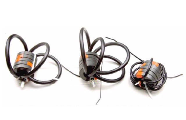
 Multiband Trap Dipole, portable short antennas, accessories and kits by DG1DBM
 -
 Experimenting OCF and dipole wire antennas over house roof. Effects of roofs on wire antennas
 -
 A dual band dipole antenna for 40 and 80 meters band. Total lenght of 26 meters, foreseen two coils at aprox 11 meters distance from center feed.
 -

-
 Documents the OC1I and OC6I IOTA DXpeditions to Peru, specifically highlighting operations from SA-098 (Isla La Leona) and SA-076 (Isla Lobos de Afuera). The OC1I team logged over **8000 QSOs** from SA-076, while OC6I made 1400 QSOs from SA-098, despite challenging propagation conditions. The resource details the equipment used, including an _IC-7000_, an IC-706mkIIG, and a TS-440SAT, along with various antennas such as a 160m dipole, FD4, G5RV, and a multi-band vertical for 17m, 20m, 30m, and 40m. The DXpedition dates are specified: OC6I operated from SA-098 between December 28 and December 30, while OC1I was active from SA-076 from January 2 to January 7. Both operations are confirmed as valid for IOTA credit. The page also includes a video link for the OC6I operation and a photo gallery from the DXpedition. Feedback is welcomed, and the webmaster is identified as Bodo Fritsche, DL3OCH.
 -
 In this article, author examine stresses placed on common-mode chokes (aka baluns) as hams use/abuse them, examine the efficiency of simple dipole multi- band antennas and their feed systems. Stressing a Balun.
 -
 An antenna for 80 meters band for those who does not have enough space to setup a halwave wire dipole that is aprox 130ft or 40 meters. The antenna is an open-wire-fed shortened dipole
 -
 An experimental prototype of an asymmetrical hatted vertical dipole antenna that can work on HF bands 20 to 10 meters band. The AHVD Vertical dipole is an upside-down T design
 -
-
 Amateur radio antennas manufacturer based in Italy. Produces HF end-fed, dipoles, and other wire antenna types, mono band and multi band antennas.
 -
 Maxcon makes and sells Amateur Radio Antennas. Double extended Zepp antenna, multiband dipoles, bazooka antennas, and VHF Jpole, made in USA
 -
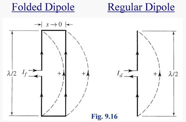 A folded dipole is an antenna, with two conductors connected on both sides, and folded to form a cylindrical closed shape, to which feed is given at the center.
 -
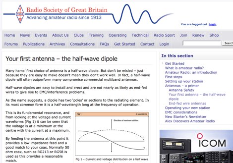 RSGB article for beginners. How to build a dipole antenna, construction tips and correct setup of inverted-ve dipole antennas
 -
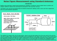 Measuring noise fiugre on the W2IMU horn and the dual-dipole-feed
 -
 This is a standard calculation method that can help you while tuning dipole antennas, by adjusting wire lengths. This method can be used also when you need to add lenght to your wires, and can be additionally used to quarter waves vertical antennas
 -
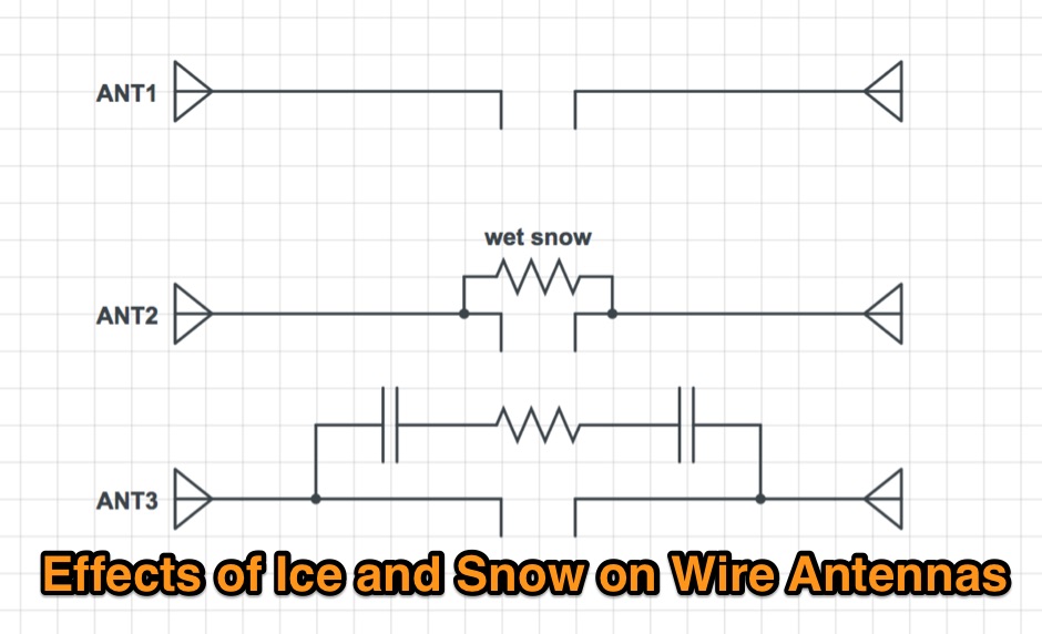 Effects of ice an snow in a wire dipole antennas
 -
 The video delves into the fascinating science behind antennas, which are crucial for receiving and transmitting electromagnetic waves. It explains how antennas convert electric signals into electromagnetic waves for transmission, and how they operate through the oscillation of positive and negative charges in dipole arrangements. Practical antenna implementations, such as dipole antennas for TV reception and Yagi-Uda antennas with reflectors and directors, are also discussed alongside modern dish TV antennas with parabolic reflectors for signal processing. It's a comprehensive overview of how antennas work and their significance in communication technology.
 -
 The resource, "Conventional Use of Transmission Line," meticulously details the operational principles of transmission lines, emphasizing the Transverse Electromagnetic (TEM) mode of energy transfer. It clarifies that for a line to function purely as a transmission line, all currents must be confined internally, with external fields ideally zero. The discussion differentiates between balanced and unbalanced lines, asserting that while both require equal and opposite currents within the conductors, the key distinction lies in the voltage relationship of each conductor to the surrounding environment. It highlights that a good antenna pattern does not inherently confirm proper feeder balance, and that common-mode currents can lead to RF in the shack and increased noise levels, even without pattern distortion. The article further explains that a transmission line can become a radiating conductor if energy is applied in a non-TEM mode, leading to common-mode issues. It cites classic texts like Jordan and Balmain's "_Electromagnetic Waves and Radiating Systems_" and Kraus's "_Antennas_" to support its definitions of TEM mode operation. The content also explores non-transmission line applications of parallel or concentric conductors, such as _coaxial dipoles_ and _folded dipoles_, which intentionally operate in non-TEM modes for antenna functionality. The author, _W8JI_, stresses that simply measuring equal currents is insufficient to confirm a balanced feeder; phase and voltage balance to ground are equally critical.
 -
 One of the featured products, the V350 CAMP, is a multiband vertical antenna covering 6 to 80 meters, priced at R$ 799,90, demonstrating the range of ready-to-use solutions available. The inventory includes various antenna types such as **HF**, **VHF**, and **UHF** designs, along with dual-band options like the J-Pole Dual V/UHF for R$ 235,00. For those building their own arrays, the store stocks essential components like element holders, clamps, junction boxes, and aluminum plates, alongside specialized items such as the KIT Isolador Central Dipolo - 01DX for R$ 99,90. The shop also provides a comprehensive selection of installation hardware, including diverse antenna mounts, PTT supports, and various coaxial cables like RG58 and RG213, with prices up to R$ 849,90 for RG213. Connectors such as UHF male PL259 and various adapters are readily available, ensuring compatibility for different setups. Additionally, specialized items like side handles for popular transceivers such as the FT857/891 and IC7300 are offered, catering to specific equipment needs. Beyond antennas, the store supplies practical accessories like transport bags, 12V power cables for transceivers, and even branded merchandise like the Antena Kit mug. Rodrigo Gonçalves, PP5BT, manages the operation from Blumenau, SC, Brazil, providing direct contact via WhatsApp at +55 47 9.9985.0155.
 -
 A portable operation experience with a SpiderBeam pole during a contest, testing wire antennas, like dipole and delta loops configurations on 20 40 and 80 meters band.
 -
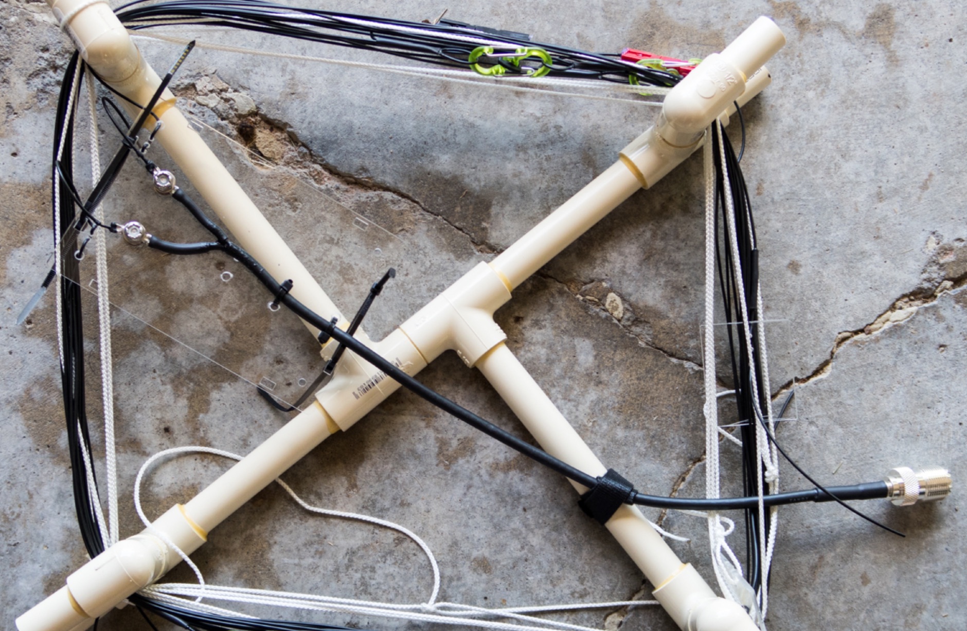 Dipole antennas are some of the simplest antennas to build in addition to being very efficient and solid performers. I wanted to make a simple dipole antenna for QRP portable operation that could be used on multiple bands.
 -
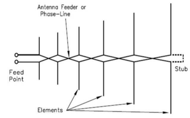 Description and online calculator for Log Periodic Dipole Arrays LPDA are directional antennas featuring a relatively constant characteristics across a wide frequency range.
 -
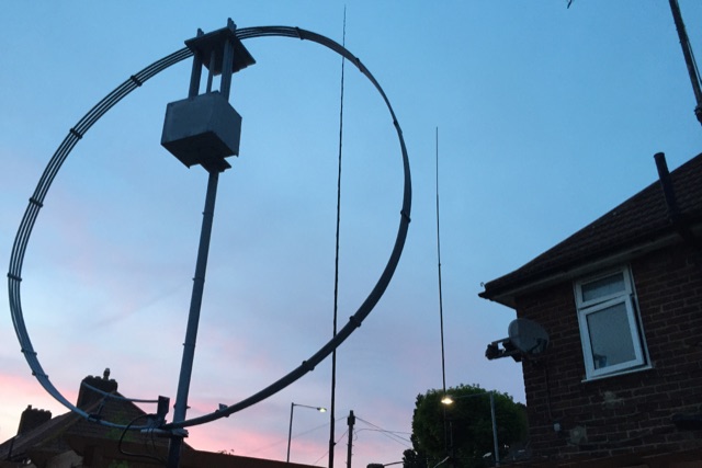 This magnetic loop DIY site is ment to be an introduction into making DX high quality magnetic loop antennas that will beat any dipole
 -
 A balun is a MUST for dipoles or similar antennas when they are feed with coaxial cable. From the RF point of view, the shield can be modeled as two conductors, the internal shield (the real shield, this is, ground) and the external shield, who is really far to be ground. In this way, your dipole has 3 arms, the two from the dipole and the coaxial cable shield (external face)
 -
 Construction tips of a basic wire antenna, the half wave dipole. Inverted V dipoles and effects of inverted v on radiation pattern.
 -
 On the field comparison among C-Pole antenna, an EFHW vertical antenna and an Inverter V dipole antenna. Test is done using two identical WSPRLite beacons that transmit with 200mW on the WSPR frequency and analyzing spotted results.
 -
 Dipole antennas, vertical half-wave dipole antennas with impedence tranformes that can be used for portable operations. Some well worn antenna configurations are the easiest and loudest lash-ups you can try.
 -
 A hexagonal beam is a form of the Yagi antenna which is based on parasitic principles developed early in the last century in Japan for achieving gain in one direction.How HexBeam antennas works. A hexagonal beam operates exactly like Yagi antenna, but instead of a driven element that is straight like a dipole, it is a wire bent into the shape of the letter M.
 -
 This PDF guide provides detailed instructions and diagrams for constructing a fan dipole antenna, a popular choice among hams for multiband operations. The guide covers the design, materials needed, and installation process, offering step-by-step guidance to help hams set up an effective antenna system for their radio operations.
 -
 Operating as FY/F5UII, Christian F5UII conducted a DXpedition to French Guiana (FY) from January 13 to 30, 2013. The primary operation utilized the FY5KE radio club station in Kourou, with activity focused on voice modes during specific weekday hours. The resource details the operator's intent to transmit before 12:00z and after 22:00z, or as availability permitted, from the mainland. A significant aspect of this operation involved a dedicated weekend activation of the Salut Islands, specifically **IOTA SA-020**, from January 19-20, 2013. This segment of the DXpedition was conducted from Royal Island (Ile Royale), part of a group including Devil's Island (Ile du Diable) and St. Joseph Island (Ile Saint Joseph), located 14 km offshore from Kourou. The station setup for the IOTA activation included 100 Watts of power, a GPA-030 vertical antenna for 10m, 15m, and 20m, and dipole antennas for 17m and 40m, with antenna deployment contingent on site conditions and propagation. The operator anticipated strong interest for the SA-020 entity.
 -
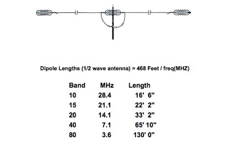
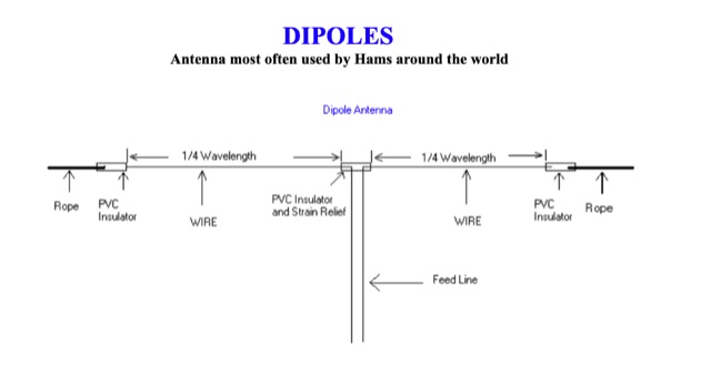 Antenna most often used by Hams around the world. Inexpensive, effective and easy to build, what more could anyone ask for in a home made antenna.
 -
 This page presents an online calculator tool for determining the dimensions of various HF wire antennas operating between 1.8-30 MHz. Users input their desired resonant frequency to obtain precise measurements for four popular antenna types: standard flat-top dipole, inverted Vee, quad loop, and equilateral delta loop. The calculator provides comprehensive measurements including leg lengths, minimum heights, horizontal spreads, and feedpoint distances. Accompanying the calculator are detailed technical explanations, construction notes, and installation guidelines for each antenna type, making it a practical resource for amateur radio operators building their own antennas.
 -
 Dipole for 40m band. It is a simple linear loaded dipole feeded with 450-Ohm openwire feedline. Designed it for resonance at 7.050 MHz, can be tuned on 30m and 80m bands with an external antenna tuner. Build with simple electrical copper wire (2.5 mmq/13 awg) and two fishing poles with size of about 7 m/23 ft.
 -
 The HB9CV antenna calculator aids amateur radio enthusiasts in designing antennas for VHF and UHF bands. By inputting the working frequency, users can obtain crucial dimensions like dipole lengths and distances. The tool, based on the HFSS antenna model, provides data on impedance, VSWR, and gain, optimizing front/back radiation ratios. It includes tips for fine-tuning using a Г-matching balun and compensating capacitor, ensuring effective performance and minimal VSWR for enhanced radio communications and direction finding.
 -
 This document details the construction of a multi-band end-fed antenna, suitable for situations with limited space for larger antennas. The design utilizes a 1:49 to 1:60 impedance transformer to match a half-wave wire antenna fed at one end. Compared to a traditional dipole, this antenna resembles a highly unbalanced Windom antenna with one very long leg and a virtual short leg. The design eliminates the need for radials but relies on the coax cable shield for grounding. The document recommends using at least 10 meters of coax and installing a common mode filter at the entry point to the shack for improved performance.
 -
 In this article the author describes his personal experience on some antennas for 50 MHz he tested on the field, the six meter Dipole, Vertical, Moxon, a 3 element Yagi and an Omniangle antenna.
 -
 This document provides a detailed guide on constructing and mounting a folded dipol for the 146 MHz frequency in a vertical configuration to be used in Yagi antennas. The step-by-step instructions and diagrams included make it easy for hams to build and set up this type of antenna. Understanding and implementing this design can enhance the performance of radio communication for Amateurs operating in the 2-meter band. Whether you are looking to improve your signal strength or experiment with antenna designs, this resource offers valuable insights and practical information.