Search results
Query: frequency meter
Links: 158 | Categories: 1
-
 Microwaves101 provides an extensive repository of information covering fundamental principles of microwave design, targeting engineers and radio amateurs interested in the higher frequency spectrum. The site features a detailed _encyclopedia_ of microwave terms and concepts, alongside practical design considerations for various components and systems. It serves as a foundational reference for understanding RF propagation, transmission lines, and active/passive microwave circuits. The resource includes numerous calculators for impedance matching, filter design, and other critical RF parameters, facilitating hands-on project development. Discussions on **10 GHz** equipment and **24 GHz** projects highlight practical amateur radio applications, extending to operations up to 134 GHz. Content spans from basic theory to advanced topics like MMIC design and antenna characteristics, supporting both educational and practical endeavors in microwave technology.
 -
 Presents Wayne Kerr Electronics, a manufacturer specializing in precision component measurement products. The company offers a range of LCR meters, impedance analyzers, and transformer test systems designed for various applications in electronics manufacturing and research. Specific product lines include the 3260B Precision Magnetics Analyzer, which measures inductance, capacitance, and resistance with high accuracy, and the 6500B series of LCR meters, capable of testing components across a broad frequency range up to 120 MHz. The 3255B and 3265B series provide solutions for transformer and inductor testing, including turns ratio, leakage inductance, and inter-winding capacitance measurements. These instruments are utilized in quality control, component characterization, and production line testing, ensuring performance and reliability in electronic circuits. Wayne Kerr's offerings support engineers and technicians in verifying component specifications.
 -
 The Waterway Net, sponsored by the Waterway Radio and Cruising Club, is dedicated to enhancing amateur radio communications for recreational boaters. Meeting daily at 0745 ET on 7.268 MHz LSB, the net focuses on safety and weather updates, providing a vital link for live-aboards and cruising boats to stay connected with families and friends. Position Reports and Float Plans are essential components that ensure safety for offshore passage makers. Established in the early sixties, the Waterway Net is one of the longest-running nets in amateur radio history. Open to all amateur radio operators with a General class license or higher, it encourages participation without requiring WRCC membership. Newcomers are advised to listen initially to understand net procedures before checking in. In emergencies, FCC regulations allow anyone, licensed or not, to use any frequency to call for help, with the 20-meter frequency of 14.300 MHz available for emergency assistance approximately eighteen hours a day.
 -
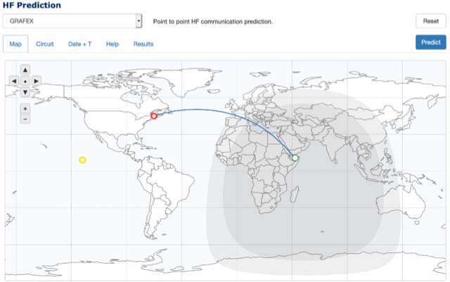 Online HF Communication prediction system provided by the Australian Governament Buerau of Metereology allow to predict usable frequency rage for radiocommunications between two stations allowing to specify frequency and date range. This tool allow calculation with different methods and algorithms
 -
 This article introduces an Arduino-based QRP CW Transceiver designed for lower HF bands. The journey begins with the Wotduino, evolving from a keyer to a multi-mode beacon. The development includes a QRP transmitter and culminates in a receiver inspired by Roy Lewallen design. The transceiver, controlled through a control bus features a signal path, modulation, filtering, and adjustable frequency settings. Despite initial testing intentions, successful QSOs on 80 and 40 meters showcase its functional capabilities.
 -
 The _G3TSO_ Mobile Antenna Page details construction and tuning methods for mobile antennas operating across **10 to 160 metres**. The content describes a Hustler-based design, optimized for RF performance and vehicle speeds, featuring centre loading. For optimal operation on various bands, the loading coil placement requires clearance from the vehicle body. Antenna resonance is critical for efficient mobile operation. A mobile antenna's base impedance may be as low as 27 ohms, requiring specific matching to achieve maximum radiation, as a minimum SWR at the transmitter does not always indicate resonance or maximum output. Tuning involves physical adjustment of antenna length to achieve resonance at the operating frequency. The _G3TSO_ page outlines a tuning procedure utilizing a low-power signal source and a field strength meter to identify maximum radiation before impedance matching. Loading coil placement, either at the base, center, or top of the antenna, influences radiation efficiency and mechanical stability for mobile installations. Centre-loaded whips, such as the Hustler design, offer a compromise between efficiency and stability, often for single-band operation. Helically wound antennas, including those for **28 MHz**, may present base impedances around 17 ohms, resulting in a 3:1 SWR at resonance. Low resistance grounding at the antenna base is also specified for optimizing performance and minimizing RFI during mobile operation. DXZone Focus: Mobile | Any | Antenna Tuning | HF
 -
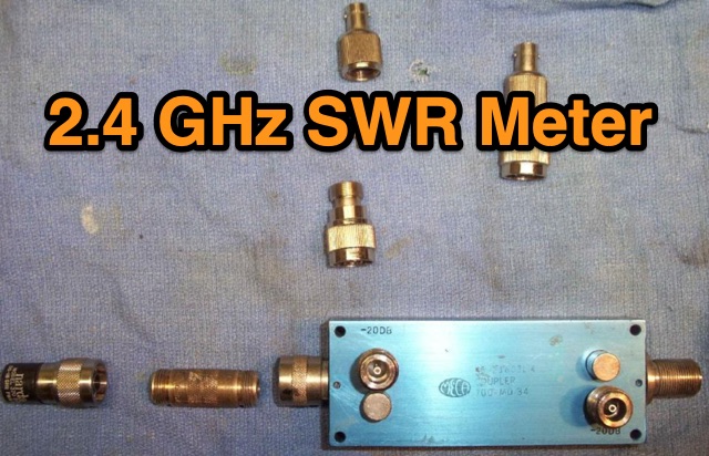 This is a simple 2.4 GHz SWR meter which is based around surplus microwave hardware which can be easily found. The main component is a MECA -20/-20 dB Directional Coupler which has a frequency range of approximately 700 MHz to 2.5 GHz.
 -
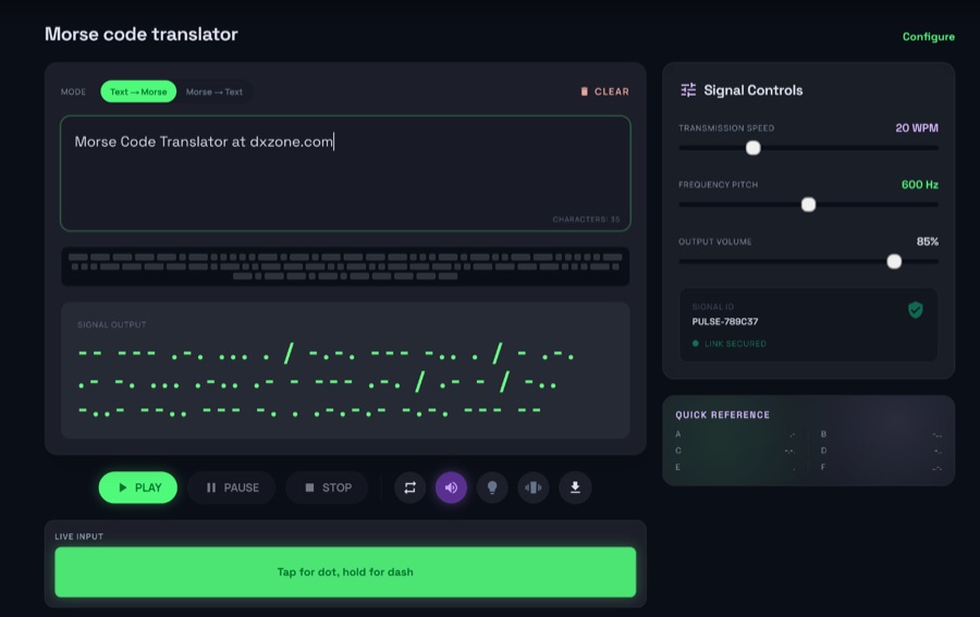 The morsecodeworld.org web application provides an online Morse code decoder and encoder, facilitating real-time conversion between text and International Morse code. It supports adjustable transmission speed (Words Per Minute), sidetone frequency pitch (Hz), and output volume, allowing users to customize their learning and practice environment. The tool includes a quick reference chart for the Morse alphabet and focuses exclusively on International Morse, aligning with contemporary amateur radio licensing and on-air practices, distinguishing it from historical American Morse code. This web-based utility enables users to type text for encoding into Morse audio or paste Morse code for decoding into plain text, offering immediate feedback on timing and character spacing. It supports both visual and auditory learning by providing adjustable parameters for speed and tone. The platform is designed for self-assessment, encouraging users to practice copying and sending, and to identify and correct common errors in character recognition and timing.
 -
 This air-core solenoid style RF inductor calculator calculates the inductance, wire size, number of turns, and other parameters for an air-core solenoid inductor used in radio frequency (RF) circuits, based on user input of frequency, desired inductance value, and physical dimensions.
 -
 Explains the fundamental purpose of a repeater, detailing how these automated relay stations overcome distance and terrain limitations for VHF/UHF communications. It traces the historical development from early Bell Telephone Labs "relay" stations in 1922 to Art Gentry, W6MEP's, pioneering K6MYK amateur radio repeater in the mid-1950s, which remains active today. The resource clarifies the distinction between simplex and duplex operation, including the unique function of a "parrot repeater" for single-frequency recording and playback. Delving into the internal workings, the guide breaks down a repeater into its core components: the antenna system, feedline (often _Heliax_ or hardline for minimal loss), duplexer, receiver, transmitter, and controller. It emphasizes the critical role of the duplexer in preventing receiver desensitization by isolating transmit and receive signals, even with distinct frequencies. The discussion highlights the importance of high-performance, durable antennas and low-loss feedlines, citing examples of equipment installed in the 1960s and 1970s that are still in perfect working order. Operating a repeater is also covered, with an explanation of frequency offset (e.g., the 600 kHz standard for 2 meters) and the function of _CTCSS_ (PL tone) for access. It outlines standard input/output offsets for various bands, from 6 meters to 23 centimeters, while noting regional variations. The guide also touches on features like autopatch and Digital Voice Recorders (DVRs), providing a solid foundation for understanding repeater technology and usage.
 -
 The antenna I built was inspired by a portable delta loop designed by Doug DeMaw, W1FB. Given that I constrained myself to a 50-foot roll of speak wire, I scaled my antenna for the 20M band. Using the formula, 1005 divided by the frequency in megahertz, I calculated a total length of 71 feet (21.6 meters) for the center of the 20M band.
 -
 Learn how to design and analyze a folded trifilar antenna for the 80-meter band. Based on a description from RAF antennas between 1940 and 1970, this article provides step-by-step guidance on modeling the antenna, calculating resonance frequency, adjusting dimensions, and verifying performance. Perfect for hams looking to improve their antenna setup for better transmission and reception on the 80M band.
 -
 This document provides a detailed guide on constructing and mounting a folded dipol for the 146 MHz frequency in a vertical configuration to be used in Yagi antennas. The step-by-step instructions and diagrams included make it easy for hams to build and set up this type of antenna. Understanding and implementing this design can enhance the performance of radio communication for Amateurs operating in the 2-meter band. Whether you are looking to improve your signal strength or experiment with antenna designs, this resource offers valuable insights and practical information.
 -
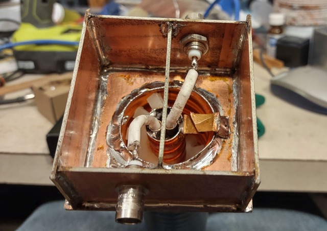 Cavity is often required at a busy site to not only prevent its receiver from being overloaded by off-frequency signals, but also be a good neighbour and prevent low-level signals from your transmitter from getting into other users receivers - not to mention the preventing of those other signal from getting back into your transmitter to generate spurious signals in its own right.
 -
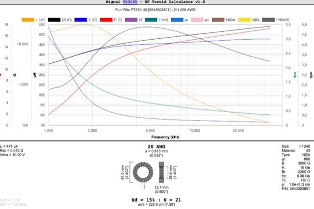 This RF Toroid Calculator provides graphical calculator used to determine the inductance and other parameters of ferrite and powdered-iron toroids. It simplifies the process of selecting the appropriate toroid for use in radio frequency (RF) circuits
 -
 This article describes the phases for the construction of a Yagi antenna. The calculations of the parameters are made using 4NEC2 software. This type of antenna is used for transmissions and receptions of electromagnetic waves. The project shown here refers to the frequency of 433.92 MHz.
 -
 Four distinct amateur radio bands, specifically 40, 30, 20, and 15 meters, are addressed by a portable dipole antenna design. This antenna utilizes a manual switching mechanism, employing "fast-on" or flying connectors to change bands. The design is presented with an animated plan, illustrating how operators can adjust the operating frequency by opening and closing specific connections on the antenna elements. The resource describes a _4 savos dipol_ (4-band dipole) that can be shortened for specific band operation. It provides practical information for hams seeking to construct a versatile, multi-band wire antenna for portable operations or fixed station use. This design offers a straightforward approach to achieving multi-band HF capability without complex tuning units, making it suitable for field deployments like SOTA or POTA activations where rapid band changes are beneficial.
 -
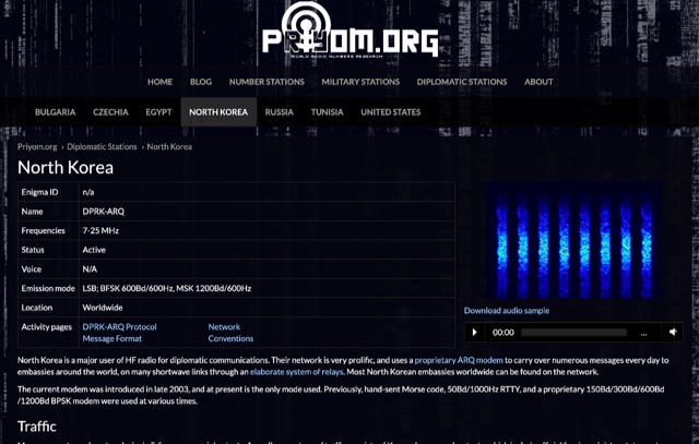 The resource details active HF radio networks maintained by foreign ministries for diplomatic communications, specifically listing operational schedules and frequencies. It currently covers networks for Bulgaria, Czechia, Egypt, North Korea, Russia, Tunisia, and the United States. The content provides specific operational parameters for these government-run shortwave stations. Information includes details on _legacy modes_ of operation and specific transmission times. The site also includes schedules for various _number stations_ which often utilize similar HF spectrum allocations. The data presented aids in identifying and monitoring these unique, non-amateur radio signals across the shortwave bands. Specific sections are dedicated to the networks of North Korea and the United States, offering granular data for each.
 -
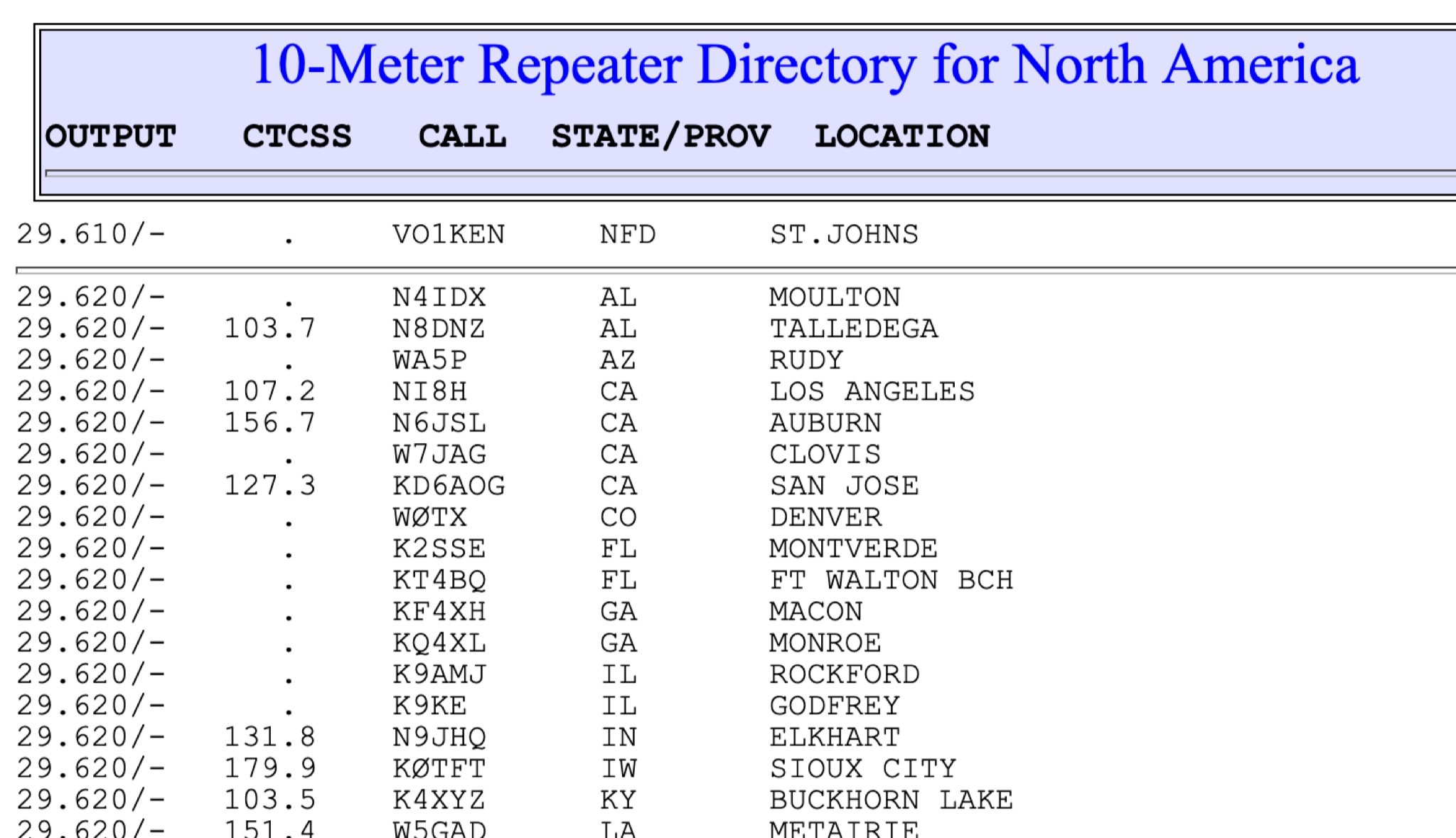 This page show a list of repeaters in north america transmitting from 28 MHz to 29 MHz. The most of them are in the 29.620 to 29.700 frequency range. Some repeaters may be active and on the air while others may not
 -
 This page provides construction details for a 4-element 10-meter Yagi antenna with 28 Ohm impedance. It includes information on the elements, positions, diagrams, and data related to frequency, gain, front-to-rear ratio, radiation resistance, SWR, and loss. The content is aimed at hams or radio operators interested in building and optimizing Yagi antennas for the 10-meter band.
 -
 An **Arduino LC Meter** provides an accessible solution for precisely measuring inductance and capacitance values, crucial for RF circuit design, filter tuning, and troubleshooting in amateur radio applications. This project details the construction of a low-cost, accurate instrument using readily available components, making it an attractive alternative to commercial units for hams and electronics enthusiasts. The build process involves assembling a resonant circuit, integrating an Arduino microcontroller for frequency measurement, and displaying results on an LCD. Key components include an Arduino Uno, a 16x2 LCD, a 74HC14 Schmitt trigger inverter, and a few passive components. The design leverages the Arduino's processing power to calculate L and C values from resonant frequency shifts. Calibration procedures are outlined to ensure measurement accuracy, which is vital for critical RF work. The project includes schematics, a parts list, and the necessary Arduino code, enabling hams to construct a functional LC meter for their workbench.
 -
 This project describes the construction of a W3HH (T2FD) antenna for HF bands (3-30 MHz). While less efficient than a tuned dipole, it offers broad frequency coverage with a maximum SWR of 3.4 and reduces QRM (noise) significantly. On the 80-meter band, it shows slightly weaker signals than a dipole but with improved signal-to-noise ratio. The design includes non-inductive resistors, a 13:1 balun, and a "frog ladder" transmission line. Though not a high-performance antenna, it is compact and versatile, making it ideal for wide-band HF communication. Article in French
 -
 The Dipole Bazooka Antenna for 40 meters is a popular choice among amateur radio operators. Its design allows for easy construction using materials like RG58 coaxial cable and PVC. Measurements are calculated using specific formulas; for instance, at a frequency of 7,100 MHz, the total length is approximately 19.74 meters. This antenna offers a performance range of 97% to 99%, with an impedance of 49 to 52 ohms. Additionally, it can handle up to 1 kW of power and requires no modifications for connection.
 -
 Learn how to design a Hentenna antenna, a portable asymmetrical double-loop antenna ideal for amateur HF or VHF bands. This page provides details on constructing and optimizing the antenna for maximum performance in DX communications. Discover how altering the antenna's vertical feed section can adjust the VSWR resonant frequency and how changing the support pole's position can alter the beam direction. Originally developed by Japanese 6-meter operators, the 'Hentenna' offers a unique design that allows for horizontal polarization when vertically oriented. Explore radiation patterns, VSWR charts, and antenna currents diagrams to optimize your antenna's performance for long-distance contacts.
 -
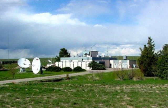 NIST radio station WWV broadcasts time and frequency information 24 hours per day, 7 days per week to millions of listeners worldwide. WWV is located near Fort Collins, Colorado, about 100 kilometers north of Denver. The broadcast information includes time announcements, standard time intervals, standard frequencies, UT1 time corrections, a BCD time code, and geophysical alerts
 -
 Addresses the common challenge of constructing effective dual-band antennas for VHF/UHF operations, specifically detailing a J-pole design. It covers the theoretical underpinnings, including calculations for quarter-wavelength radiator and stub sections, accounting for velocity factor and design frequency. The resource provides practical construction guidance using readily available materials like TV twin lead and coaxial cable, culminating in an antenna with a total length of approximately 52 inches. Performance metrics are presented, showing a measured SWR of 1.7:1 or better across most of the 2-meter band and less than 2:1 across the 70-cm band. These SWR measurements, referenced to 50-ohm impedance, were taken at the transmitter end of the feed line. The article also touches upon the necessity of a balun for proper impedance matching between the balanced J-pole and unbalanced coaxial feed line, suggesting a split-core cylindrical ferrite for this purpose.
 -
 This resource details the construction and performance of a compact broadband magnetic loop antenna designed for portable receiving applications with devices like the _ATS MiniRadio_. The antenna utilizes approximately 3 meters of 0.5–1 mm copper wire wound in two turns on a rhomboidal wooden frame, measuring 50 cm by 70 cm. It connects via a modified 9:1 unun, where the primary center tap is isolated from ground to improve common-mode noise rejection. The design provides untuned operation across a frequency range from the longwave band up to approximately 25 MHz. Performance characteristics include observable directivity for noise suppression and the ability to connect directly to a radio or via a 50 coaxial cable for remote operation. The article specifies the unun's 3:1 turns ratio and its SMA output for connectivity. The methodology focuses on practical construction and observed reception quality.
 -
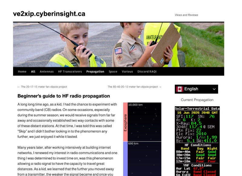 High Frequency (HF) radio propagation, particularly the phenomenon of "Skip," which enables long-distance radio contacts, is thoroughly explained for newcomers to the amateur radio hobby. The article begins by defining essential terms such as _radio signal_, atmosphere, troposphere, stratosphere, mesosphere, thermosphere, exosphere, and aurora, setting a foundational understanding for subsequent discussions. A significant portion of the content focuses on the ionosphere, identifying it as the primary driver of HF propagation. Its structure, including the D, E (E1, E2, E3), and F (F1, F2) layers, is detailed, along with how solar radiation influences these layers to refract radio waves back to Earth. The concept of "The band is opened!" is introduced, specifically noting refraction around **21 MHz**. The guide also touches upon ground waves, space waves, and temperature inversions affecting VHF/UHF propagation, contrasting them with the dynamic nature of ionospheric HF propagation. Factors like antenna polarization, takeoff angle, and the sun's solar cycle are mentioned as critical influences on signal path, with examples like 80-meter band propagation after sunset and 40-meter/20-meter bands offering near-constant propagation.
 -
 Effective suppression of harmonics and parasitic radiation from HF transmitters is crucial, especially with the increasing sensitivity of VHF/UHF radio channels to interference. This project details a hybrid low-pass filter (LPF) designed to operate across the HF bands up to 51 MHz, making it suitable for 6-meter band operations while providing deep VHF/UHF suppression. The design addresses the challenge of modern interference landscapes, where even microvolt-level signals can disrupt wireless sensors and other simple VHF/UHF receivers. The filter utilizes a single elliptic link, combining high cutoff steepness with robust suppression in the hundreds of megahertz range. A key feature is the use of only two standard capacitor values, simplifying construction and component sourcing. The article provides a detailed schematic, performance characteristics, and _RFSim99_ model file, demonstrating a reflection coefficient S11 below 0.017 (VSWR < 1.03) across 1-51 MHz, ensuring minimal degradation to the antenna system. Construction notes include coil winding specifications and capacitor selection guidance, with recommendations for _FR-4_ assembly. Two capacitor sets are presented, with the first variant recommended for its lower RF current demands, keeping currents below 3 A at 1 kW passing power at 51 MHz. Fine-tuning involves adjusting frameless coils, with considerations for capacitor tolerance and high-frequency capacitance measurement accuracy.
 -
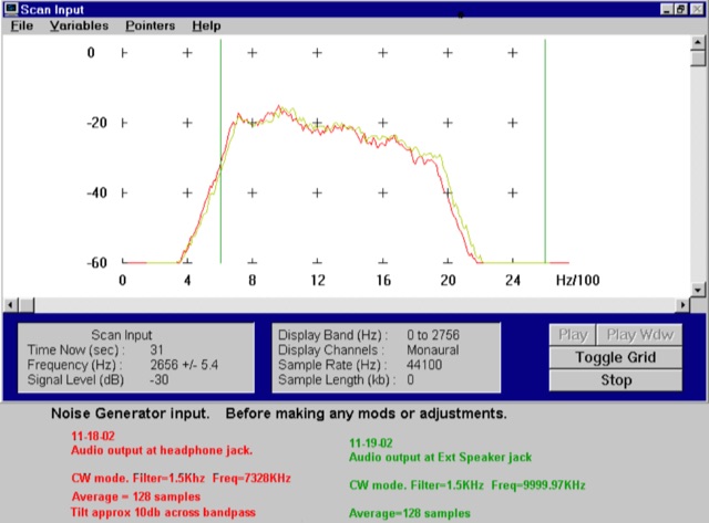 Spectrogram, a PC-based audio frequency spectrum analyzer available from Visualization Software, aids ham radio enthusiasts in aligning receivers like Elecraft K2. Versions are downloadable, with an intuitive interface and customizable parameters. Tutorials by experts like Tom Hammond and John Grebenkemper offer additional guidance.
 -
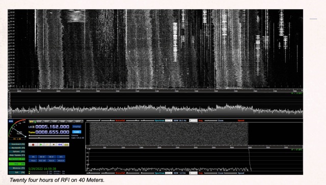 Demonstrates the application of Software-Defined Radios (SDRs) as effective tools for conducting Radio Frequency Interference (RFI) site surveys. The resource details the methodology for capturing and analyzing RFI, specifically focusing on the 80-meter band over a 24-hour period. It outlines the setup of an SDR-based survey tool, utilizing software like _S-Meter Lite_ and _Spectrum Lab_ to visualize and quantify noise sources. The article emphasizes the SDR's wideband capabilities, which allow for comprehensive identification and documentation of RFI across broad frequency ranges, crucial for effective mitigation strategies. The analysis presents practical results, illustrating how continuous monitoring can reveal intermittent RFI sources that might otherwise go undetected. For instance, the survey identified noise peaks exceeding **S9+20dB** on 80 meters during specific hours, correlating with local appliance usage. The methodology provides a repeatable process for hams to characterize their local noise floor, enabling targeted RFI suppression efforts and improving weak-signal reception, particularly for DXing and contesting.
 -
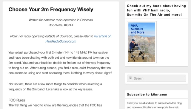 When new to the 2-meter FM transceiver, securing a quiet frequency for chatter seems straightforward, but it's essential to navigate FCC rules and band plans effectively. Even though frequency allocations are consistent above 50 MHz for Technician licenses, adherence to specific segments within the 2m band—ranging from 144 MHz to 148 MHz—is crucial. This includes respecting designations for different modes like CW, SSB, and FM to prevent interference, particularly with satellites and exotic modes like EME. Understanding and following the structured band plans not only ensures legal compliance but also optimizes frequency use and minimizes disruptions in the amateur radio community.
 -
 This program simplifies the complex jumper calculations for the PRF1520 radio, which can be a pain to determine manually. It supports common crystal frequencies and channel spacings, advising if a desired frequency is achievable. A recent feature allows determining unknown frequencies of a newly obtained radio by setting the jumper positions and other parameters.
 -
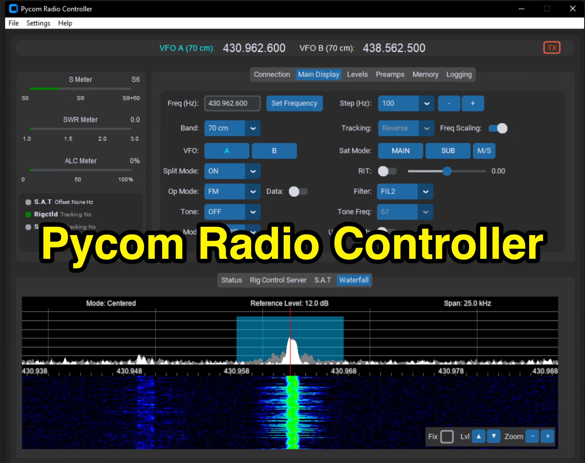 The Icom IC-9700 transceiver, a popular choice for VHF/UHF/1.2 GHz operations, gains enhanced remote control capabilities through Pycom Radio Controller. This software provides direct _CI-V based control_, enabling operators to manage frequency, mode, memories, and tones from a connected computer. It integrates a built-in rigctl server and supports popular satellite tools like Gpredict and SatPC32, facilitating full duplex Doppler control for satellite passes. Key features include real-time meters, a waterfall display, and remote RC-28 integration. Designed for practical amateur radio use, the application streamlines voice and digital satellite operations. It allows for full duplex remote Doppler control, crucial for maintaining accurate frequencies during satellite contacts. The software also incorporates callsign lookup and logging functions, alongside enhanced memory management. Documentation pages offer configuration guidance and operating examples, ensuring users can effectively set up and utilize the software for their satellite communication needs, potentially improving success rates for contacts and contests.
 -
 Operating amateur radio repeaters involves understanding frequency offsets, CTCSS tones, and the basic signal flow through a repeater system. This resource details the fundamental concepts of repeater operation, including the distinction between input and output frequencies, the role of **CTCSS (Continuous Tone-Coded Squelch System)** for access, and the typical frequency bands utilized for local communication. It clarifies terms such as "simplex" versus "duplex" operation and provides a diagram illustrating the signal path from a handheld transceiver to a repeater and back to another station, emphasizing the range extension repeaters offer. The article further explains practical aspects like identifying a repeater's offset (e.g., +600 kHz for 2-meter band) and the necessity of programming the correct tone. It compares the operational benefits of using repeaters for local communication over direct simplex contacts, highlighting how repeaters overcome line-of-sight limitations. The content is structured to assist new licensees in confidently making their first repeater contacts, providing a foundational understanding of how these critical infrastructure components facilitate wider area coverage for VHF/UHF amateur radio.
 -
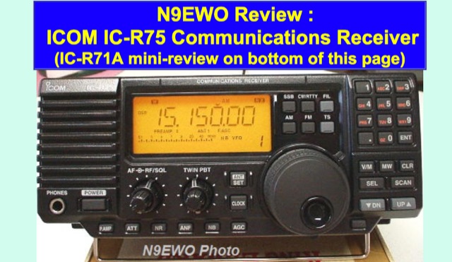 Icom IC-R75 tabletop HF communications receiver came onto the market back in 1999 and was taken out of production in late 2015. Frequency coverage is from 30 hz right to 60 MHz. This allows one to catch the 6 Meter amateur band as well.
 -
 KISS703 is a 703 Hz narrowband digital mode for amateur radio, designed for simple, low-power operation without computers. A 500 Hz pilot tone ensures frequency alignment, replaced by unique tones for 37 symbols (letters, numbers, space). Built from common discrete components, it draws about 40 mA at 12 V, ideal for SOTA/IOTA use. The receiver uses amplification, wave shaping, and a pulse-counting frequency meter for manual decoding via a calibrated meter. Transmitter and receiver calibration involves marking meter positions for each tone, enabling fully self-contained messaging with minimal hardware in portable or fixed operations.
 -
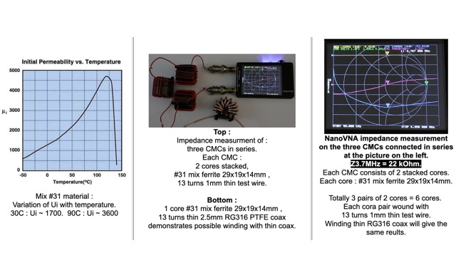 The influence of temperature changes in Common Mode Chokes. To get an indication of the impedance behavior when the core temperature changes, the author tested a CMC by heating it with a hairdryer, and measuring its temperature with an infrared thermometer. When the CMC temperature rises from 30C to 90C, the frequency of maximal impedance shifts down from ca.10 MHz to ca.7.2 MHz, or by a factor 1.4.
 -
 This is a theoretical look at propagation on 630-Meters and 2200-Meters using ray tracing software. It expands on the brief discussion in the ARRL Handbooks. The Earth's magnetic field affects 630-Meter and 2200-Meter band propagation. Lower ionization reduces absorption, aiding low-frequency propagation. Differences exist between bands, limited daytime sky-wave propagation. Sunrise/sunset show promise, yet mechanisms are unclear. Ducting possible at night in specific conditions. Negative ions enhance propagation. Inefficient antennas and high man-made noise are anticipated. Groundwave propagation is significant on 2200-Meters.
 -
 A dual insert microphone design for the Icom IC-7300 transceiver utilizes a **Besson BZ2400 M4 Rocking Armature** insert for frequencies from 500 Hz to 3 kHz, exhibiting a rising response of approximately 11 dB. A generic Electret Condenser insert, powered by the transceiver's microphone line, covers the low-frequency range from 100 Hz to 500 Hz. A Low Pass Filter is incorporated after the Electret insert to prevent frequency overlap, and a pre-set potentiometer (VR1) adjusts the low-frequency response, balancing the output of both inserts. The design emphasizes a "Close Talking" arrangement and addresses audio "colorization" by housing the Besson insert in a thick rubber holder with a foam boot, separate from the circuitry, with the Electret insert also wrapped in a foam boot. Critical importance is placed on using the correct BZ2400 M4 insert with 12 holes in its face plate. The frequency response table for the BZ2400 M4 insert shows 0 dB at 500 Hz, rising to +11 dB at 3000 Hz, while the Electret insert with the Low Pass Filter provides 0 dB at 100 Hz, rolling off to -9 dB at 500 Hz and -50 dB at 3000 Hz. This combination ensures a broad, balanced audio spectrum for SSB operation. The project includes a circuit diagram, a comprehensive parts list detailing components like a 1 Henry iron-cored inductor (L1) and various capacitors, and a board layout within the metal tube. The completed unit provides a tailored audio profile for the IC-7300, enhancing transmit audio quality.
 -
 YAGio 1.01 is a Windows-based software for designing DL6WU long Yagi antennas on VHF and UHF frequencies. It supports Windows 2000, XP, Vista, 7, and likely 8. Using keyboard commands, users input specifications such as frequency, gain, and element diameters, and YAGio generates the design. You can download latest Yagio version from this page. Results can be saved in YIO, NEC, YAG, MMA, and YC6 formats, or printed directly.
 -
 The project details the construction of a GM3OXX OXO transmitter, designed to accommodate **FT-243 crystals** using 3D-printed FX-243 holders from John KC9ON. It presents specific frequency adjustments, noting a 7030 KHz HC-49/s crystal could be tuned from 7029.8 KHz to 7031.7 KHz with an internal 45pF trimmer capacitor. The build incorporates a modified keying circuit to prevent oscillator run-on key-up and includes a TX/RX switch for sidetone via a connected receiver, with the transmitter output routed to a dummy load on receive. Practical construction aspects are thoroughly covered, including the process of cutting a rectangular opening in a diecast enclosure for the FT-243 socket and the selection of a **low-pass filter** (LPF) based on the QRP Labs kit, derived from the W3NQN design. The author achieved approximately 800mW output power from a 14.75V supply, measured with an NM0S QRPoMeter, using a 16.5-ohm emitter resistor in the 2N3866 final stage. The article also touches upon the potential for frequency agility across the 40M band using multiple FX-243 units with various crystals. The narrative includes a brief diversion into Bob W3BBO's recent homebrew projects, such as his Ugly Weekender MK II transceiver, highlighting the enduring appeal of classic QRP designs. The author reflects on the personal satisfaction derived from building RF-generating equipment, irrespective of DX achievements, and shares experiences of making local contacts with the 800mW OXO transmitter on 40 meters.
 -
 145 MHz is the target frequency for this 2-meter Skeleton Slot Yagi Stack antenna project. The design focuses on feeding two stacked Yagi antennas using a skeleton slot radiator, which is a unique approach for VHF enthusiasts. The project details the construction process, including the loop tapered matching section for impedance matching, ensuring optimal performance. The use of specific components like the EH789 element holder and MB456 main mast bracket is highlighted, providing clarity on the assembly process. The construction utilizes 20x20 box aluminum bar for durability and precision. Key dimensions, such as the element length (ER-ED4) and main boom spacing (MM123), are meticulously outlined. This attention to detail aids in replicating the antenna design accurately. The downloadable PDF offers comprehensive instructions, making it accessible for amateur radio operators interested in VHF antenna construction. This project is particularly beneficial for those looking to optimize their 2-meter band operations. The inclusion of a skeleton slot radiator and loop tapered matching section demonstrates advanced techniques in antenna design, catering to both intermediate and advanced builders.
 -
 Assessing the ICOM IC-R9000 communications receiver, this review details its operational parameters and user experience for radio enthusiasts. Introduced in 1985, the IC-R9000 covers a broad frequency spectrum from 0.1 MHz to 1999.8 MHz, making it suitable for a wide array of listening activities from medium wave (MW) to VHF/UHF. Key performance metrics include a dynamic range of **102 dB** with the narrow SSB filter, crucial for discerning weak signals in crowded bands, and its substantial physical dimensions of 424 x 150 x 365 mm and 20 kg weight. The receiver's architecture supports various modes, though it notably lacks synchronous detection, a feature often desired for improved AM reception under fading conditions. It incorporates 1000 memory channels and robust scanning capabilities, facilitating efficient monitoring across its extensive frequency range. This analysis provides insights into the IC-R9000's capabilities and limitations, offering a historical perspective on a significant piece of amateur radio and shortwave listening hardware.
 -
 The Olivia digital mode, a **Multi-Frequency Shift Keying (MFSK)** radioteletype protocol, is specifically engineered for robust communication under difficult propagation conditions on shortwave radio bands from 3 MHz to 30 MHz. Developed by Pawel Jalocha in 2003, Olivia signals can be decoded even when the noise amplitude exceeds the digital signal by over ten times, making it highly effective for transmitting ASCII characters across noisy channels with significant fading and propagation phasing. Early on-the-air tests by Fred OH/DK4ZC and Les VK2DSG on the Europe-Australia 20-meter path demonstrated intercontinental contacts with as little as one-watt RF power under favorable conditions. Common Olivia modes are designated as X/Y, where X represents the number of tones and Y is the bandwidth in Hertz, with examples including 8/250, 16/500, and 32/1000. The resource clarifies that Olivia, unlike some other digital modes, produces a constant envelope, allowing RF power amplifiers to achieve greater conversion efficiencies and making it less prone to non-linearity. Operators are advised that **Automatic Level Control (ALC)** can be set higher than no meter movement for MFSK modulation, as long as it's not driven past its high limit, contrary to common misinformation about other digital modes. The Olivia community encourages voluntary channelization on suggested calling frequencies, such as 14.0725 MHz for 8/250, to facilitate initial contacts, especially for signals below the noise floor. The Olivia Digital DXers Club provides links to Groups.io, Facebook, and Discord for community engagement and offers details on QSO parties.
 -
 Twenty 1-watt carbon film resistors are configured in parallel to construct a 50-ohm **dummy load** for amateur radio applications. The design incorporates a heatsink for thermal dissipation and an **SO-239 connector** for RF input, making it suitable for QRP operations. This budget-friendly project details component selection, soldering techniques, and mounting procedures, achieving a continuous power rating of 10 watts and intermittent handling of up to 100 watts across HF and VHF frequency ranges. The resource provides a step-by-step guide for assembly. This construction offers an economical solution for essential shack tasks such as antenna tuning, transmitter testing, and SWR meter calibration without radiating an RF signal. The utilization of readily available components significantly reduces the overall build cost compared to commercial alternatives, providing radio amateurs with a functional and reliable test accessory. While specific VSWR measurements are not provided, the design prioritizes practical utility for low-power transceiver diagnostics and general RF experimentation.
 -
 After years of reliable performance, a 26-year-old Icom 706MK2G exhibited an unusual deviation during FM transmission, with the actual frequency being 10kHz off from the displayed frequency. Additionally, the power meter showed a sharp dip during transmission. Upon investigation, it was discovered that the FM VCO voltage adjust variable had become dirty and sluggish over time. By adjusting the variable capacitor and cleaning it with switch cleaner, the issue was resolved, restoring stable power output and accurate frequency transmission.
 -
 The **Yaesu FRG-100** shortwave receiver, introduced in 1992, operates across a frequency range of 50 kHz to 30 MHz, accommodating AM, LSB, USB, and CW modes, with an optional narrow-band FM capability. Its physical dimensions are 238 x 93 x 243 mm, with a weight of 3 kg, making it suitable for both portable and fixed station deployments. Power options include standard mains voltage or 12VDC, providing operational flexibility for diverse listening environments. The front panel integrates a manual tuning knob, an analogue signal strength meter, and an LCD display that provides critical information such as frequency, operating mode, memory channel, and time. Users can configure various operational parameters, including tuning steps and bandwidth filters, to optimize reception for specific signals. This review highlights the FRG-100's straightforward interface and its utility for shortwave listening enthusiasts. The design emphasizes user-friendly adjustments for settings, which contributes to its appeal among those interested in general coverage reception.
 -
 Over 200 distinct 2-meter band amateur radio repeaters are cataloged for Australia, providing essential operational data for VHF communication. Each entry specifies the repeater's output frequency, often including the input tone (e.g., **91.5 Hz** or **123.0 Hz** CTCSS) and the repeater's callsign (e.g., _VK2RSC_, _VK3RHF_). Locations are precisely noted, frequently referencing specific towns, mountains, or geographical features such as "Kinglake, Kangaroo Ground" or "Adaminaby, Mars Hill." The resource also indicates various digital modes and linking capabilities where applicable, such as "FMEchoLinkFusionWIRES-X" or "DMR," alongside standard FM operation. This detailed listing facilitates local and regional VHF communication, enabling hams to program their transceivers accurately for repeater access. The data is presented in a clear, tabular format, making it straightforward to identify repeaters by frequency and location.
 -
 Demonstrates various technical projects and tutorials for amateur radio operators, focusing on digital modes, monitoring, and station setup. It covers topics such as implementing a _WSPR_ station, setting up ADS-B reception, configuring a _DXSpider_ cluster, and utilizing monitoring tools like Prometheus and Grafana. The resource provides practical guides for integrating modern IT solutions with ham radio activities, including Docker and Linux environments for radio applications. This site also features a publicly accessible online logbook, offering detailed statistics on QSOs by band, mode, and geographical zone, with visual mapping of contacts. It includes a comprehensive amateur radio lexicon, explaining hundreds of terms, and provides a real-time display of the F4HXN station's local weather conditions. The resource also aggregates information on upcoming ham radio events and offers a **SWR simulator** for antenna analysis, allowing users to visualize ROS changes based on frequency and antenna parameters.