Search results
Query: pic
Links: 698 | Categories: 6
-
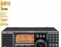 Large picture of Icom IC-718 by Rigpix database
 -
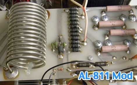 Pictures of the Ameritron AL-811 modification for 10 meter band extension by km5ps
 -
 Well documented Amateur Radio HF/VHF antenna projects, high power Russian GS35B RF amplifiers, mobile RFI solutions, related accessories, vintage radios, Six meter equipment, and useful techniques by K8CU are inside.
 -
 The EF0604S is a compact 4 elements yagi antenna plan for six meters band featuring 8.77 dBi gain and a front back gain of 17.89 dB. Article includes elements dimensions and spacing, along to pictures of some homebrewed examples.
 -
-
 5 Band 1/4 wave Telescopic Antenna. The 20m to 10m, antenna is simple and cheap to make, and has a performance that matches commercial antennas but at cost considerably lower. The design was purposely based on a telescoping fibre glass fishing rod as this allows it to be easily stowed away in the car.
 -
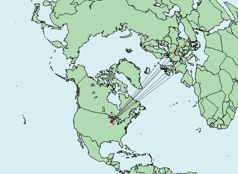 Write down grid squares of your QSOs and this nice online tool will create a World map with all contacts QTH linked to your home QTH. The QSO map picture can be downloaded for resharing.
 -
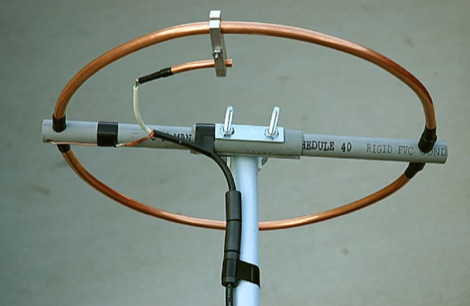 2 Meter Halo Antenna project by Mike Fedler with many detailed pictues and detailes homebrewing instructions so you can build your own
 -
 Explains the Federal Communications Commission (FCC) vanity call sign program, outlining the specific rules and procedures for amateur radio operators in the United States to obtain a personalized call sign. It details the eligibility requirements based on license class, the application process using FCC Form 605, and the various group formats (e.g., _1x2_, _2x1_, _2x2_) available to different license classes, such as Extra and Advanced. The resource clarifies the priority system for vanity call sign requests, including previous holders and close relatives, and discusses the typical processing times for applications. It also provides insights into how the FCC assigns available call signs and offers practical advice for increasing the likelihood of securing a desired call, referencing the _ARRL Letter_ for updates.
 -
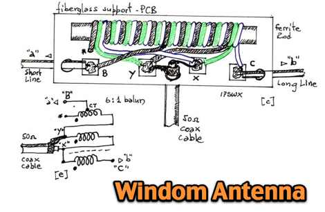 A windom multiband antenna project with pictures and diagram for the 6:1 balun
 -
 Stone vintage radio describes early radio from marconi to the 1960s. its covers antique radio, wireless, tubes, valves, crystal sets, and battery radios. included in the virtual museum are hundreds of pictures, images, and descriptions of antique radios, articles, faq, sell, and buy a radio.
 -
 AA5TB home made CW paddles, pictures and construction details
 -
 The K8ZT website provides a curated collection of amateur radio resources, encompassing software tools, informational articles, and external links relevant to various aspects of the hobby. It features utilities for _log analysis_, insights into QRP operations, and guidance on obtaining vanity callsigns. The site also includes sections dedicated to shack design principles and general ham radio information, reflecting a broad interest in practical station setup and operational enhancements. Specific software offerings are presented alongside discussions on their application, such as tools for analyzing contest logs to identify operational efficiencies or areas for improvement. The content often integrates personal experience with technical explanations, providing a practical perspective on topics like antenna selection for low-power operations or optimizing station workflow. The resource distinguishes itself by combining software recommendations with contextual information, aiding operators in making informed decisions about their station's technical and operational aspects.
 -
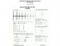 ON6MU optimized 6/9 element vhf yagui antenna with antenna schematic plan and pictures of homebrewed samples.
 -
 Detailed pictures of Titan DX
 -
 Pictures and circuit diagramm to build this power amplifier for 2 meters
 -
 ICANN policies require registrars to verify domain registrant email addresses within 15 days of registration or transfer, a critical step for maintaining domain activity. Failure to complete this verification process results in the suspension of the domain, rendering the associated website inaccessible. This resource details the common reasons for such suspensions, including new registrations, changes to registrant email addresses, or domain transfers where verification was not completed. To reactivate a suspended domain, the registrant must click a verification link sent to their email address by the registrar. The process typically resolves the suspension within 30 minutes after successful verification. Registrants can request a resend of the verification email through their domain provider or use a trigger code if available. This ensures compliance with ICANN's _Registrant Verification Policy_ and restores website functionality.
 -
 The PIC-MORSE is an electronic iambic keyer, integrating a generator of Morse code and a sidetone. It is built with a microcontroller PIC16C711. In French
 -
 Theory, Modeling, and Practical Applications By W5JCK, presentation in PDF File. This presentation focuses on Near-Vertical Incidence Skywave (NVIS) antennas, which are crucial for short-range radio communications, particularly in military and emergency contexts. It explores NVIS theory, antenna models, and installation criteria while debunking common myths about reflectors. Key topics include usable frequency bands, optimal installation heights, and the impact of soil quality on performance. The presentation outlines the best bands for daytime and nighttime use, emphasizing the importance of understanding propagation characteristics to enhance communication effectiveness within 200 to 300 miles.
 -
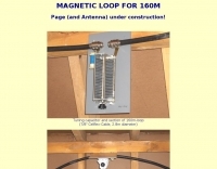 Pictures and calculated values for this home made magnetic loop antenna for the 160 meters band by HB9MTN
 -
 The article "Exploring the World of 10 Meter Beacons" by Ken Reitz, KS4ZR, provides an in-depth look at 10-meter beacon operations, focusing on their utility for propagation analysis. It details FCC Rules part 97.203 governing beacon stations, including license requirements, power limits (under 100 watts), and the specified band segment of 28.200-28.300 MHz for U.S. operations. The content highlights the diversity in beacon construction, from converted CB radios to home-brew QRP transmitters, and discusses the robust operating conditions these 24/7 stations endure. The resource presents several case studies of active 10-meter beacon operators like Ron Anderson KA0PSE/B, Domenic Bianco KC9GNK/B, and Bill Hays WJ5O/B, detailing their equipment, antenna setups, and typical signal report volumes. It also introduces the NCDXF/IARU International Beacon Project, which features 18 synchronized beacons worldwide transmitting on 28.200 MHz at varying power levels (100W, 10W, 1W, 100mW) to facilitate propagation testing. The article also covers the PropNet Project utilizing PSK31 on 28.131 MHz and the 250 Synchronized Propagation Beacon Project on 28.250 MHz. Practical advice for monitoring includes using the RST reporting method, understanding the impact of the solar cycle on 10-meter propagation, and tips for setting up a personal beacon, such as frequency selection and power output considerations. The IY4M Guglielmo Marconi Memorial Beacon Robot on 28.195 MHz is also mentioned for its automatic QSO mode. The article concludes with a list of other resources for 10-meter beacon information.
 -
 Almost a fresh QSL manager Database, Country Tables for YPLOG by VE6YP (updated monthly), Additional files for the TRLoog by N6TR. Technical topics for HF Contesting (mostly CW), software download (a huge collection)
 -
 Morse Code Keyers / Processors and other PIC products. CW RTTY serial and usb interfaces and keyers kits.
 -
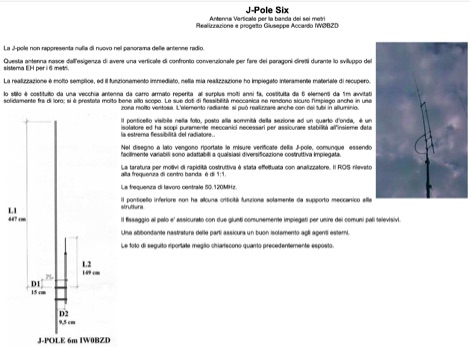 Homebrewed jpole antenna for 50 mhz by IW0BZD, include pictures and schematics, in italian.
 -
-
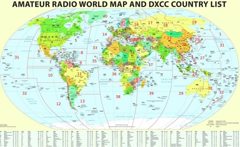 Large picture of a 2011 amateur radio map with DXCC country list
 -
 Online shop based in hong kong offer batteries mic speakers adaptors programming cables earpieces telescopic antennas handheld antennas desktop chargers handheld speakers. Kenwood Icom Yaesu and Alinco dealer
 -
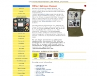 This resource catalogs a significant collection of historical military radio equipment, detailing various sets from World War II and the Cold War eras. It presents information on British, German, Japanese, USA, and other nations' wireless apparatus, including specific models like the _WS-19_, R1155, and WS-18, alongside clandestine spy equipment. The content covers the preservation and restoration of these historical items, with research results published on the site. The site provides dedicated sections for different national origins of equipment, such as "British sets," "German sets," and "North American sets," allowing for focused exploration of specific military communication technologies. It also features specialized pages on topics like the _Enigma machine_, PARASET builds, and historical events such as Arnhem and D-Day, contextualizing the use of these radios in significant military operations. The collection includes detailed descriptions and images of transmitters, receivers, and associated gear. The museum, located in Kidderminster, Worcs, U.K., organizes physical exhibitions and actively seeks new equipment for its collection, emphasizing its role in preserving military radio history.
 -
 Typical question about scanning from a prospective new operator
 -
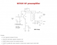 Schematic and pictures of a W7IUV preamplifier
 -
 What You Should Know About Lightning Protection by Joseph H. Reisert
 -
 Constructing a Lindenblad antenna for 137MHz NOAA satellite reception involves specific design considerations for optimal performance. The resource details the use of 4mm galvanised steel fencing wire, 300-ohm television ribbon cable, and wood/plastic components for the antenna structure. Key dimensions for a 137.58MHz-resonant antenna are provided, derived from the ARRL Satellite Handbook, specifying s, l, w, and d as 42, 926, 893, and 654mm respectively. The antenna is designed for Right Hand Circularly Polarised (RHCP) signals, requiring the four folded dipole elements to be tilted clockwise by 30 degrees. A significant aspect covered is impedance matching between the antenna's 75-ohm impedance and a typical 50-ohm receiver input. A twelfth-wave matching transformer, constructed from 117mm sections of 50-ohm RG-58 and 75-ohm RG-59 coax with a 0.66 velocity factor, is described. The article also addresses coaxial cable and connector selection, recommending 75-ohm Type-N connectors for RG-6 cable in professional setups and F56/F59 connectors for general use, while strongly advising against PL-259/SO-259 connectors for VHF. Strategies for mitigating Radio Frequency Interference (RFI) are discussed, including antenna placement to shield from local TV transmitters and the use of commercial or DIY band-pass filters, such as cavity resonators or helical notch filters, along with ferrite chokes on coaxial cables. Antenna orientation is explored, noting the Lindenblad's 'cone of silence' directly overhead and its maximized sensitivity towards the horizon. An experimental vertical tilt of 90 degrees is presented as a method to improve overhead reception and reduce interference from strong horizontal signals, particularly relevant in high RFI environments like the Siding Spring Observatory site.
 -
 An assortment of Amateur Radio-related technical articles written for the JUG, the newsletter of the Northern California Contest Club. Topics include unique but simple and useful radio modifications and accessories, and rig reviews.
 -
 Excel sheet containing technical comparisons of commercial HF portable antennas compiled by ON4SKY. Includes pictures, manufacturer, db gain, band coverage, F/B ratio, price, weight and dimensions.
 -
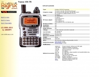 Picture and specifications for Yaesu VX-7R
 -
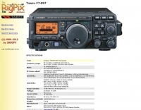 Rigpix database large picture of the Yaesu FT-897
 -
 A vertical antenna for 40 and 80 meters band with no need of antenna tuner, based on a telescopic fiberglass mast of 48 feet by N8NSN
 -
 Presents the design and construction of the OK2FJ Bigatas, a portable, automatically tuned vertical antenna covering 80 through 10 meters. It details two distinct control systems: one utilizing BCD band data from Yaesu FT-857/897 transceivers, and another employing voltage level sensing for the Yaesu FT-817. The resource provides specific instructions for building the antenna's radiating element, loading coil with switchable taps, and the control circuitry, emphasizing the use of readily available components. The article outlines the physical construction of the antenna, including the use of duralumin tubes for the radiator and a PVC tube for the coil form. It specifies coil winding details, tap points, and the integration of radial wires for ground plane operation. The control electronics section provides schematics and component lists for both the BCD decoder (using a 74LS42 IC) and the voltage comparator (using an _LM3914_ bargraph driver), enabling rapid, automatic band switching without the minute-long tuning delays common in other systems. Crucially, the antenna achieves rapid band changes, with typical SWR values centered on common operating segments, such as **3.7 MHz** for 80m SSB. It also discusses modifications for CW operation on 80m and the trade-offs between antenna efficiency and full-range automatic tuning on higher HF bands, where manual adjustment of radiator length is suggested for optimal performance on 15m, 12m, and 10m. The resource includes construction photos and a discussion of cable requirements for reliable operation.
 -
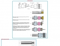 How to make easily your N-type connector, pictures and procedure, step by step
 -
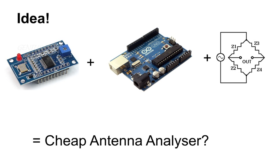 Build your own home made Antenna Analyzer with an arduino micro, or a cheeper one with a pic processor
 -
 The I0JXX is an italian company that offers market their projects, also sells electronic products of high quality, both for Ham, both Broadcast and their accessories. VHF Antennas, mosfet power amplifiers, filters, insulators, power dividers, telescopic poles, antenna masts
 -
 These pages are entirely devoted to the Kenwood TS570 series Transceivers. Specifications & Brochure, Pictures, Schematics, Reviews, Manual and Modifications.
 -
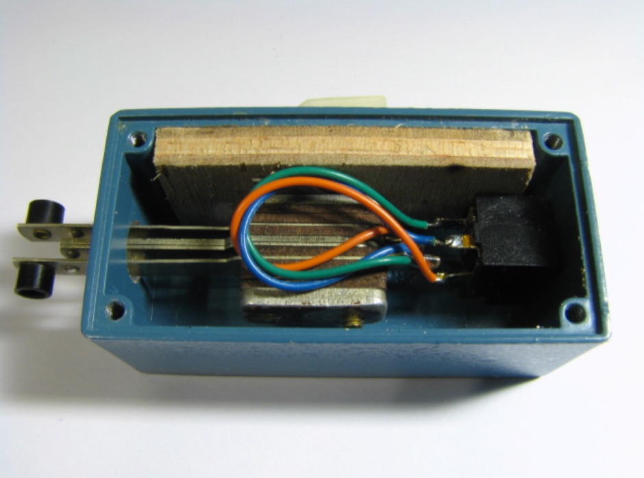
 The W1TAG LF Receiving Loop is a specialized antenna project for LF reception, designed to mitigate local noise and enhance weak signal pickup on the lower frequencies. This square loop, measuring 6 feet per side, utilizes 14 turns of #12 THHN wire wound on a PVC frame, offering a robust mechanical structure. The design incorporates a series-tuned circuit with a coupling transformer, allowing for tuning from over 400 kHz down to _45 kHz_ using a switched capacitor bank. Construction details include the use of 1.5-inch PVC pipe for the frame, with specific measurements for spreaders and drilled holes for wire threading. The two 7-turn sections of wire are connected at the center, providing an option for a center tap. The loop rotates on a 1-inch steel pipe, enabling directional nulling of noise sources. The tuning unit, housed in a box clamped to the PVC, employs a 1:2 step-up transformer wound on an _FT-82-77 core_ and uses relays to switch capacitance values from 50 pF to 6400 pF, providing precise frequency adjustment. The current setup connects to the shack via 100 feet of RG-58, feeding into a W1VD-designed preamp, with plans for a balanced, shielded twisted pair cable upgrade.
 -
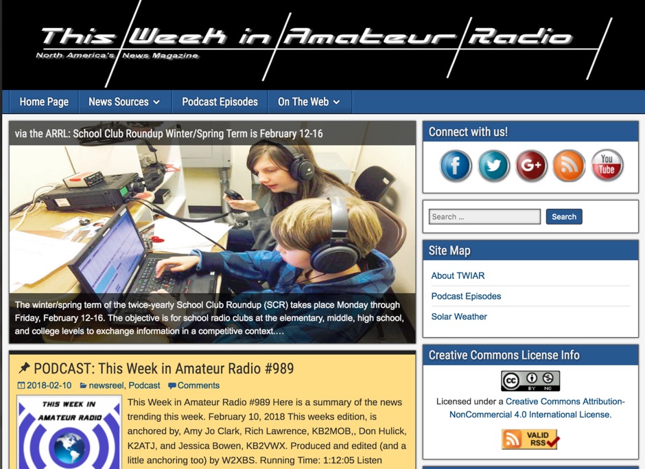 7.5 MHz wideband audio delivered via AMC-7 satellite transponder 5 provides a robust platform for disseminating amateur radio news. This service caters to operators seeking timely updates on regulations, technology, and DX news. The bulletin is accessible in both MP3 and RealAudio formats, ensuring compatibility with a wide range of devices and listening preferences. Regularly updated content keeps amateur radio enthusiasts informed about the latest developments in the hobby. The service covers a broad spectrum of topics, including contesting, digital modes, and antenna technology. By leveraging satellite and internet distribution, it reaches a global audience, making it a vital resource for operators worldwide. Listeners can expect a consistent flow of information, with new episodes released frequently. The service's commitment to providing high-quality content ensures that amateur radio operators remain well-informed and engaged with the community.
 -
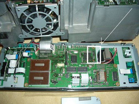 Instructions to modify the ICOM IC-7600 to extend reception and trasmission
 -
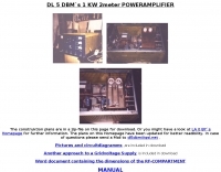
 Page on amplification topics. From vacuum tubes to various components, discussion on stability and arcin causes.
 -
-
 Pictures of a 2 meter, 220, 440 copper J-Pole antennas
 -
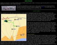
 The TU2T DXpedition log provides a critical resource for verifying contacts made during the 2011 operation from _Ivory Coast_. This online tool allows operators to quickly confirm their QSOs, which is essential for QSLing and award applications. Users can typically search by callsign, date, or band to locate specific entries, ensuring accuracy for their personal logbooks. Such online logs are indispensable for DXers pursuing awards like **DXCC**, as they offer immediate confirmation of rare or distant contacts. The ability to verify a QSO without waiting for a physical QSL card significantly streamlines the award application process. This particular log facilitates the confirmation of contacts with the TU2T operation, a highly sought-after entity.
 -