Search results
Query: tri ban antenna
Links: 184 | Categories: 2
-
 Refurbishing my 10 years old Cushcraft A3S triband HF Antenna
 -
 Operating a ham station often involves encountering radio frequency interference (RFI), RF feedback, or RF burns, which are frequently misattributed to poor equipment grounding. This resource meticulously dissects these assumptions, asserting that RF grounds on the operating desk often merely mask more significant system flaws. It identifies five primary causes for RF problems, including antenna system design flaws, proximity of the antenna to the operating position, DC power supply ground loops, equipment design defects, and poorly installed connectors or defective cables. The content emphasizes that issues like "hot cabinets" or changes in SWR when connecting a ground indicate substantial RF flowing over wiring or cabinets, a phenomenon known as common-mode current. The article provides detailed explanations of common-mode current generation, particularly from single-wire fed antennas like longwires, random wires, and OCF dipoles, which inherently present high levels of RF in the shack. It also illustrates how vertical antennas, lacking a perfect ground system, can excite feed lines with significant common-mode current. Through simulations, the author demonstrates how a dipole without a proper _balun_ can cause RF problems at the operating desk, showing current patterns and voltage distributions on feed line shields. The discussion extends to the proper application of _RF isolators_ and _ferrite beads_, clarifying their role in modifying common-mode impedance on cable shields and cautioning against their use as a band-aid for fundamental system defects. The resource advocates for correcting the actual source of RF problems, such as antenna system issues or poor connector mounting, rather than relying on internal shack grounding or isolators. It highlights that properly functioning two-conductor feed lines, like coaxial or open-wire lines, should result in minimal RF levels at the operating position, even without a desk RF ground. The author shares personal experience, noting that his stations since the late 1970s have operated without RF grounds at the desks, relying instead on proper antenna system design and feed line integrity.
 -
 A distributed capacity coaxial dipole antenna. The antenna is very broadbanded with a very flat swr on all band when setup of the antenna is done at the proper lenght and height.
 -
 The 160-meter amateur radio band, spanning 1.8 to 2 MHz, was historically the lowest frequency amateur allocation until the introduction of the 630-meter and 2200-meter bands. ITU Region 1 allocates 1.81–2 MHz, while other regions use 1.8–2 MHz. This band, often called "Top Band" or "Gentleman's Band," was established by the International Radiotelegraph Conference in Washington, D.C., on October 4, 1927, with an initial allocation of 1.715–2 MHz. Effective operation on 160 meters presents significant challenges due to the large antenna sizes required; a quarter-wavelength monopole is over 130 feet, and horizontal dipoles need similar heights. Propagation is typically local during the day, but long-distance contacts are common at night, especially around sunrise and sunset, and during solar minimums. The band experienced a resurgence after the LORAN-A system was phased out in North America in December 1980, leading to the removal of power restrictions.
 -
 Over 15 years of operational notes are documented on the AA6E Station Log, covering diverse amateur radio topics. The blog presents detailed accounts of station setup, antenna experiments, and digital mode operations, often featuring specific equipment like the _Ten-Tec Orion_ transceiver. It includes practical discussions on **station grounding techniques** and insights into PSK31 Morse code communication. The resource provides a chronological record of Martin Ewing's amateur radio activities, offering firsthand perspectives on equipment performance and operational challenges. Content often includes technical observations and solutions developed through practical experience, such as optimizing antenna systems for various bands. Specific entries detail contest participation and DX chasing, providing context for operational decisions and results.
 -
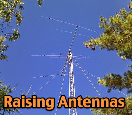 VE3VN describe in this article how to raise a tri-band yagi antenna onto a DMX-52 tower with pictures and schemas that cover the whole raising process.
 -
 The article, "Using 75 Ohm CATV Coaxial Cable," details methods for employing readily available 75-ohm CATV hardline in standard 50-ohm amateur radio setups. It addresses the inherent impedance mismatch and practical considerations, such as connector compatibility, for hams seeking cost-effective, low-loss feedline solutions. The resource specifically contrasts common 50-ohm cables like RG-8, RG213, and _LMR-400_ with 75-ohm hardline, highlighting the latter's lower loss characteristics, particularly at VHF and UHF frequencies. It explores two primary approaches to manage the impedance difference: direct connection with an acceptable SWR compromise and precise impedance transformation. The direct connection method acknowledges that a perfect 1:1 SWR is not always critical, especially when using low-loss coax. For impedance transformation, the article explains the use of half-wavelength sections of coax to reflect the antenna's 50-ohm impedance back to the transmitter, noting its single-frequency effectiveness. It also briefly mentions transformer designs using toroid cores and a technique involving two 1/12 wavelength sections of feedline for broader bandwidth. The content further clarifies the concept of _velocity factor_ for calculating electrical versus physical cable lengths, providing a generic formula for precise length determination. It notes that while half-wave matching is practical for 10 meters and above, it can result in excessively long runs for lower bands like 160 meters, potentially adding **250 feet** of cable. The article also mentions achieving a usable bandwidth of 28.000 MHz up to at least **28.8 MHz** on 10 meters with specific transformation techniques.
 -
 This web article details the construction of a 4-meter band coaxial dipole antenna, designed for operation between **70.000 MHz and 70.500 MHz**. The resource provides a bill of materials and step-by-step assembly instructions for a half-wave dipole constructed from _RG-58_ coaxial cable. The design specifies a direct 50 ohm feedpoint impedance, eliminating the need for an external matching network. Construction photographs illustrate the stripping and soldering processes for the coaxial cable elements, ensuring proper electrical connection and physical integrity. The article includes specific dimensions for the radiating elements, derived from calculations for the 70 MHz band. The project outlines the physical dimensions required for resonance at 70 MHz, with the outer braid forming one half and the inner conductor forming the other. The feedline connection is directly to the coaxial dipole's center, maintaining a 50 ohm characteristic impedance. While the article does not present SWR plots or VNA sweeps, it focuses on the mechanical construction and dimensional accuracy for achieving a functional 4-meter dipole. The design is intended for fixed station use, with no specific mention of polarization or height above ground, but implies a standard horizontal orientation for dipole operation. DXZone Focus: Web Article | 4m Coaxial Dipole | Construction Guide | 50 ohm Feed
 -
 Documents the construction of a **VHF/UHF** antenna addition for the Buddipole HF antenna system, leveraging the existing Versa-Tee component. The project details the fabrication of a custom antenna mount from angle aluminum, including specific drilling and tapping for 3/16"-24 bolts, and the creation of radials from Simpson Strong Tie Insulation Supports. It specifies radial lengths for 70 centimeters (6 inches from the center stud) and 2 meters (19 1/4 inches), noting the use of wire nuts for safety. The resource outlines the construction of a mast from 1/2" ID PVC conduit, connected with 3/8"-24 connecting nuts and bolts, mirroring the Buddipole's modular design. It describes the integration of a mobile dual-band antenna with a 3/8"-24 mounting stud and the custom coax setup with BNC and **PL-259** connectors. Field testing with an FT-817ND and a separate dual-band SWR meter confirmed good SWR on both 2 meters and the 440-450 MHz section of 70 centimeters, with positive reception reports during Field Day activities. Further, the article describes the creation of a custom carrying solution, including a 22-inch tripod bag and a fabric roll-up, to emulate the portability of the original Buddipole system.
 -
 An interesting presetnation full of usefull tricks to correctly design and build 23 cm Yagi using simple tools. The basic design of the antenna presented in this document is taken from the original DL6WU Yagi Design published in 1982
 -
 The AT-AUTO automatic antenna tuner handles 1.5kW CW operation, employing stepper motors under microprocessor control to precisely position a roller inductor and air-dielectric variable capacitor, avoiding relay-switched discrete components. This design choice prevents loud relay clacking and burning contacts, a common issue with competing products. The tuner features auto-retuning capabilities and receives periodic firmware updates, ensuring continuous improvement and added user-requested features. Its companion product, the _CX-AUTO_ coaxial switch, also features an embedded microprocessor controller. It enables selection of 1-of-8 coaxial outputs via a serial data interface. When integrated with the _AT-AUTO_, the tuner can associate specific coaxial outputs with amateur radio bands, automatically commanding the _CX-AUTO_ to select the correct antenna when the operator QSYs to a different band. Don Kessler began designing the AT-AUTO in 2005, with its debut at the 2006 Dayton Hamvention. Kessler Engineering also offers custom RF product design and electrical engineering consulting, specializing in Class-E RF amplifiers.
 -
 Over 20 distinct discussion categories are available on the Amateur Radio Discussion forum, encompassing a wide array of topics relevant to radio enthusiasts in the UK and beyond. The platform facilitates exchanges on technical aspects of amateur radio, including antenna designs, equipment reviews, and operating practices across different bands. Specific sections are dedicated to CB radio and shortwave listening, broadening its appeal beyond licensed amateurs. The forum's structure supports detailed discussions on operational challenges like the "Work All Postcodes" award, which encourages contacts across UK postal districts. Members can track personal statistics, manage contacts, and engage in challenges, fostering community participation and skill development. The resource provides a centralized hub for sharing knowledge and experiences among radio operators, offering practical insights into diverse radio communication facets.
 -
 Constructing a dip oscillator provides radio amateurs with a fundamental piece of test equipment for resonant circuit analysis. This particular design, adapted by VK3YE from a concept by _Drew Diamond VK3XU_, details a practical build using readily available components. The unit incorporates four plug-in coils, covering a frequency range from **2.6 MHz to 55 MHz**, mounted on 5-pin DIN plugs for versatility. A salvaged two-gang air dielectric variable capacitor, fitted with a vernier reduction drive, serves as the tuning mechanism, with the smaller gang optimizing bandspread at higher frequencies. In practical application, the dip oscillator is used by setting the meter needle to approximately two-thirds scale. When the instrument's coil is brought near a tuned circuit under test, a noticeable dip in the meter reading indicates resonance. This allows for precise measurement of resonant frequencies in antennas, filters, and other RF circuitry, proving invaluable for homebrewing and troubleshooting. The design emphasizes short wire runs for stable operation, particularly at the higher end of its operational range.
 -
 The Kenwood TS-870S HF transceiver features two state-of-the-art 24-bit 20 MIPS DSP chips, providing over 100dB out-of-passband attenuation and CW bandwidth adjustable to 50 Hz. It operates across 160-10 meters with 100 watts output, incorporating digital filtering, a beat canceller, and 100 memory channels. The radio also includes a transmit equalizer, RX antenna input, and a K1 Logic Keyer, enhancing signal processing and operational flexibility for amateur radio operators. Advanced capabilities include IF stage DSP, dual noise reduction, and an auto notch filter, all contributing to superior signal reception and clarity. The TS-870S offers a variable AGC, voice equalizer, and an RS-232C port for computer control, with Windows™ software supplied. Its built-in automatic antenna tuner functions on all bands for both transmit and receive modes, streamlining station setup and operation. Available accessories such as the DRU-3A digital recording unit, SO-2 high stability crystal oscillator, and VS-2 voice synthesizer option further extend the transceiver's utility. The unit requires 13.8 VDC at 20.5 Amps and is supplied with an MC-43S hand microphone, making it a comprehensive station component.
 -
 Examines Radio Frequency Systems (RFS), a manufacturer specializing in high-performance cable solutions for diverse communication infrastructures. The company, with over 120 years of heritage, focuses on designing and producing robust, long-life connectivity systems, including _low loss foam dielectric RF cable_ and _premium radiating cable_. RFS's product range supports critical applications in cellular networks, microwave antenna systems, and specialized installations within buildings and tunnels. The resource highlights RFS's commitment to innovation, addressing emerging industry standards like _FRMCS_ for railway communication and advanced fiber solutions for data centers. It also details the company's manufacturing capabilities in Hannover, Germany, emphasizing the quality and reliability associated with _Made in Germany_ products. The content covers various connectivity landscapes, from urban solutions for connected cities to private 5G credentials and future plans. Specific product categories include _fiber, power & hybrid cable_, and _low loss high power air dielectric RF cable_, showcasing their broad portfolio for complex RF environments.
 -
 A six meter band 3 element yagi beam antenna project with shortened elements using coax cables with the outer ends stripped and the center conductor shorted in somewhat of a Bazooka antenna.
 -
 Presents field test results for an **elevated SuperAntenna MP-1** portable antenna, configured on a tripod for HF operations. The resource details the antenna's setup and performance during a portable activation, focusing on its use across the 40-meter, 20-meter, and 17-meter amateur bands. It includes observations on signal reports and operational considerations for this specific portable antenna configuration. The content provides practical insights into deploying the MP-1 antenna in a non-ground-mounted setup, which is often a point of interest for portable and QRP operators. It documents the author's experience with the antenna's tuning and effectiveness for making contacts under real-world conditions, offering a user-perspective review of its capabilities. The article also features photographic evidence of the antenna's deployment, illustrating the tripod mounting and the overall portable station setup.
 -
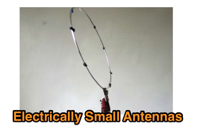 An antenna system is electrically small if it's enclosing sphere is <λ/2π. So a 10m band antenna of under 1.6m long qualifies.
 -
 An experimental prototype of an asymmetrical hatted vertical dipole antenna that can work on HF bands 20 to 10 meters band. The AHVD Vertical dipole is an upside-down T design
 -
 Details Amphenol's extensive product line, encompassing electrical, electronic, and fiber optic connectors, alongside coaxial and flat-ribbon cable solutions. The company designs, manufactures, and markets these interconnect systems globally, serving various communication network requirements. Their offerings support end-to-end connectivity, crucial for modern broadband infrastructure. Emphasizes the company's role as a major provider of components vital for reliable signal transmission in diverse applications. Products like _LMR(R) coaxial cables_ and various _RF connectors_ are essential for amateur radio installations, ensuring low loss and robust connections for antennas and transceivers. The focus on high-performance interconnects directly benefits hams constructing or upgrading their stations. Amphenol's broad portfolio includes specialized connectors and cable assemblies, meeting rigorous technical specifications for both commercial and amateur radio use.
 -
 Presents _Beam Quest_, the official Japanese distributor for _SteppIR_ antennas, detailing their product lineup and services. The site showcases various _SteppIR_ Yagi models, including the _Dream Beam_ series (DB42, DB36, DB18E, DB11) with configurations from two to four elements, alongside the _Big IR_ and _Small IR_ vertical antennas. It also lists accessories such as TX/RX and PC interfaces, essential for integrating these advanced antenna systems into a ham shack. Operators often seek out _SteppIR_ antennas for their dynamically adjustable element lengths, which allow for optimization across multiple bands, a significant advantage for DXing and contesting. This adaptability contrasts sharply with fixed-element Yagis, providing a distinct edge in varying band conditions. The resource provides contact information, including email and phone numbers, for inquiries and support regarding _SteppIR_ products within Japan, serving as a direct point of contact for sales and technical assistance.
 -
 A loop antenna for 80 and 40 meters band, the main loop is based by a crossed line using aluminium strip lines. The main loop diameter is 150 cm.
 -
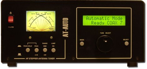 _AT Auto_ is an automatic antenna tuner designed for amateur radio enthusiasts seeking efficient and reliable tuning solutions. This device automates the tuning process, allowing operators to focus on communication rather than manual adjustments. The tuner is compatible with a range of transceivers, enhancing its versatility in different shack setups. Its design incorporates advanced circuitry to ensure optimal performance across various bands. The _AT Auto_ tuner is particularly useful for those operating in HF bands, providing seamless transitions between frequencies. Its integration capabilities with other shack automation products make it a valuable component for modern amateur radio stations. The tuner supports multiple modes, including _SSB_ and _CW_, catering to diverse operating preferences. Its robust construction and user-friendly interface contribute to its appeal among both seasoned operators and those new to the hobby. Kessler Engineering's focus on innovation and quality is evident in the _AT Auto_'s design. The tuner is part of a broader product line that includes shack automation solutions, reflecting the company's commitment to enhancing amateur radio operations. Despite the website redesign, the tuner remains a key offering in their product portfolio.
 -
 The ZS1J/B beacon operates on 28.2025 MHz with 5 Watts output to a half-wave, end-fed vertical antenna, initially installed in 1977 as ZS5VHF near Durban. The 10-meter transmitter is a modified 23-channel CB radio, and the identification keyer uses a diode matrix unit with TTL ICs from the same era. After relocation to Plettenberg Bay in 1993, the beacon has been in continuous service, with additional QRP transmitters later installed for other bands. In 1994, a single-transistor, 80-meter, 0.5-watt QRP transmitter with a half-wave dipole was added on 3586 kHz, followed by a 160-meter, 0.5-watt unit on 1817 kHz. A 30-meter, 0.5-watt transmitter was installed in 1996, operating on 10.124 MHz. In 2002, a 40-meter QRRP beacon on 7029 kHz, with an output of 100 microwatts, achieved DX reports up to 1100 km from ZS6UT in Pretoria. Best DX reports for the 80m and 160m beacons came from 9J2BO.
 -
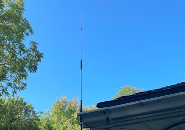
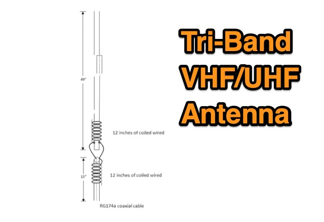 The TBJ-1 – a triband base antenna was published in March 2017 QST. This antenna covers 2M/220 MHz/70cm in one 6ft 3/4 inch PVC pipe and requires no radials.
 -
 Basic magnetic loop antenna examples and loop aerials theory explained. This article inclued some interesting tricks on building magnetic loop antennas and an usefull excell sheet to help compute magneti loop antennas calculating power efficiency from 10 to 40 meters band
 -
 Efficient Low Band Counterpoise for Restricted Circumstances Loss Avoidance Opportunities and Techniques for the Low Bands The short and linear FCP was designed to reduce ground losses from inadequate radial systems beneath inverted L and other vertical antennas.
 -
 The Tri-pole antenna, a clever modification of a standard dipole, allows for dual-band operation by integrating a third element. This design effectively shortens the overall dipole length by 10 to 20 percent, simplifying antenna rotation and offering a compact footprint. KK4OBI's article delves into the operational principles, using a 6 and 10-meter Tri-pole as a primary example, and provides comprehensive instructions for constructing any Tri-pole antenna within the 6 to 15-meter range. Key to the Tri-pole's performance is its off-center feed, necessitating a common mode choke at the feed point for optimal tuning and reduced noise. The author outlines a methodical approach to determining element dimensions, starting with a vertical element frequency calculated as 0.47 times the sum of the desired upper and lower band frequencies. This calculation, along with K-values derived from trend lines, guides the initial lengths for the horizontal arms, demonstrating how a 10m-6m Tri-pole can achieve a total horizontal length 78% shorter than a conventional 10-meter dipole. Tuning and balancing are critical, with the article detailing adjustments to arm lengths and the vertical element to achieve balanced SWR values, as validated through 4NEC2 simulations. Radiation patterns are analyzed at various elevations, showing gains around 5.7 dBi and favorable take-off angles for DX contacts. Construction details specify aluminum tubing dimensions, U-bolts, and an SO-239 connector, emphasizing the importance of a ferrite-based choke for wideband operation.
 -
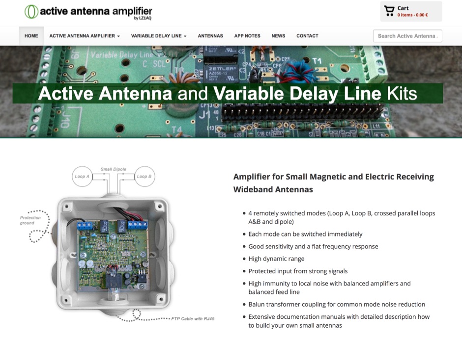 Manufacturer of amplifier for small magnetic and electric receiving wideband antennas, and variable delay line kit for active antenna phased arrays
 -
 Presents amateur radio activities and experiences from JJ0LUU and JJ0LXF, two operators based in Japan. The weblog, hosted on shinshu.fm, documents their on-air operations, equipment setups, and general ham radio interests. Content often includes details about specific contacts, antenna configurations, and local operating conditions within the Japanese amateur radio community. The resource primarily focuses on personal operating logs and occasional technical discussions relevant to their station. It offers a glimpse into the daily life and pursuits of Japanese **amateur radio** operators, detailing their engagement with various bands and modes. JJ0LUU and JJ0LXF share their passion for radio communication, contributing to the broader online repository of individual ham radio narratives. The site serves as a digital logbook and informal platform for sharing their **DXing** and contesting endeavors.
 -
 DF0WD/DL4YHF's Longwave Overview details amateur radio operations on the 135.7 to 137.8 kHz segment in Germany. The author outlines the "inofficial" European band plan, specifying segments for QRSS, TX tests, beacons, conventional CW, and data modes. Early LF activities at DF0WD began with a 20-watt CW transmitter, later upgraded to a homemade linear transverter capable of 100 watts, driven by an Icom IC706 on 10.137 MHz. The station's antenna system includes a 200-meter wire, approximately 10 meters above ground, supported by football field light-masts. Despite its length, the antenna's efficiency is noted as very low due to the immense wavelength of about 2.2 km. The author's experience highlights the significant challenge of achieving effective radiated power (EIRP) on LF, estimating DF0WD's EIRP at around 80 milliwatts based on field strength measurements from PA0SE. DF0WD/DL4YHF has successfully worked numerous countries on 136 kHz CW, including DL, F, G, GI, GM, GU, GW, HB9, HB0, LX, OE, OH, OK, OM, ON, OZ, PA, and SM. The author also mentions ongoing efforts to log contacts with CT, EI, LA/LG, and to complete a two-way QSO with Italy, demonstrating persistent activity on this challenging band.
 -
 The Terminated End Fed Vee Antenna (TEFV) is a travelling wave antenna with constant current distribution. Unlike traditional resonant antennas, TEFV operates without standing waves, using a terminating resistor for broadband efficiency. With a combination of vertical and horizontal polarization, it offers wide bandwidth from 1.8 MHz to 30 MHz, eliminating the need for a tuner. Key components include a 9:1 unun transformer and a 500-ohm terminating resistor. Grounding and counterpoise enhance performance, and it can handle power losses of up to 30%. TEFV provides an effective, versatile antenna solution for amateur radio and broadcast applications.
 -
 Presents various amateur radio topics through blog posts, detailing operational experiences and technical insights from the perspective of SV2YC. The content frequently discusses antenna projects, such as a **portable 20m/40m dipole** designed for rapid deployment, and explores the performance characteristics of different wire configurations in varied field conditions. Observations on propagation and band activity across the HF spectrum are also regularly documented, providing practical context for fellow operators. Specific entries often include detailed accounts of **DX contacts** and participation in minor contests, outlining station setup, power levels, and antenna choices. The blog also covers modifications to commercial transceivers and homebrew accessory construction, offering practical advice on improving station efficiency and functionality. Further posts delve into software applications for logging and digital modes, sharing configurations and operational tips for maximizing their utility in daily amateur radio activities.
 -
 Messi & Paoloni offers a range of RF coaxial cables, including the _Ultraflex_ series, specifically engineered for amateur radio applications. These cables feature advanced dielectric materials and high-density braiding, resulting in significantly reduced attenuation across HF, VHF, and UHF bands. For instance, the Ultraflex 7 exhibits a loss of only **2.5 dB per 100 feet** at 144 MHz, making it suitable for demanding DX and contesting operations. The company's product line also includes specialized connectors, such as N-type and PL-259, designed to maintain optimal impedance matching and minimize signal reflections. Each connector is precision-machined to ensure a secure, weather-resistant termination, crucial for outdoor antenna installations and long-term reliability. Messi & Paoloni emphasizes rigorous quality control, with all cables undergoing testing to ensure consistent performance and durability, supporting effective two-way radio communication.
 -
 Constructing a dual-band antenna for 40 and 20 meters often involves compromises in size or complexity. This resource presents a compact _open sleeve dipole_ design that addresses these challenges by using 450-ohm ladder line and folded elements to achieve a total length of approximately **17.17 meters**, significantly shorter than a full-size 40-meter dipole. The design leverages electromagnetic coupling, where a primary radiator handles the 40-meter band, and a second conductor resonates on 20 meters without direct electrical connection. This configuration eliminates the need for traditional traps, loading coils, or switching components, simplifying construction and reducing potential loss points. The antenna is fed with RG-58C/U coaxial cable, and a common-mode choke is recommended at the feed point to suppress sheath currents, ensuring a cleaner radiation pattern and minimizing RF in the shack. The design is well-suited for portable operations, field deployments, temporary installations, and restricted urban environments where space is a premium, offering solid performance on both HF bands.
 -
 PRO-LINK specializes in the manufacturing and distribution of high-quality cabling solutions, including a wide array of fiber optic cables and various coaxial cable types. Their product line encompasses 50-ohm and 75-ohm coaxial cables, essential for diverse RF applications, alongside specialized RF cables and 10Base-T networking cables. The company also provides a selection of connectors and custom cable harnesses, catering to specific installation requirements. Since 1988, PRO-LINK has offered a 5-year warranty on its products, underscoring a commitment to durability and performance. The product catalog details specifications for different cable constructions, such as _RG-58_, _RG-213_, and _LMR-400_ equivalents, which are commonly used in amateur radio installations for antenna feedlines and inter-component connections. Their offerings support both commercial and amateur radio operators seeking reliable signal transmission. The company's focus on robust cable and connector solutions addresses the critical need for low-loss transmission lines in radio communication systems, ensuring signal integrity across various frequency bands.
 -
 A 60-foot available space, for example, might necessitate a shortened multiband dipole array to cover 80, 40, and 15 meters effectively. This resource details the construction of such an antenna, combining full-size and coil-loaded dipoles on a single feedline. It addresses the common challenge of fitting multiple HF bands into restricted physical footprints, providing practical guidance for hams with smaller backyards or portable operations. The core of the offering is an interactive calculator that determines required loading coil inductance and dipole lengths for various amateur bands from 160m to 10m. Users input their available space, and the tool provides dimensions, coil turns, and an efficiency rating (Good or Fair) based on the antenna's electrical length relative to a quarter-wavelength. It also suggests suitable _PVC_ pipe diameters for coil forms. The article further illustrates a center feed-point assembly using an 18-inch section of 2-inch _PVC_ pipe, detailing eye-bolt spacing and coaxial connector installation. It emphasizes the importance of adequate spacing between parallel dipoles and offers customization options for the feed-point, including the addition of a _Balun_ for improved feedline isolation.
 -
 Discovering a solution for limited space, the inverted L HF antenna emerges as a stellar performer. Half the size of a dipole, it ensures optimal installation in restricted areas, maintaining superb transmission (TX) and reception (RX) characteristics. Spectrum Communications' multi-band version, featuring traps, proves even more space-friendly without compromising performance. A fiberglass pole offers sturdy support, while proper grounding, an RF choke, and occasional tuning contribute to a high-performing and reliable antenna system.
 -
 This active antenna for the shortwave band provides surprising performance, even indoors. As the name implies, the main loop is made from a Hula-Hoop with the metallic paint stripped off and a single turn of 14AWG copper wire inserted inside the hoop.
 -
 Operating in antenna-restricted communities presents unique challenges for amateur radio operators, often necessitating creative solutions for antenna deployment. This resource details the design and implementation of stealth antennas within a townhouse community in Exton, PA, where external antennas were strictly forbidden by covenants. The author, WB5NHL, describes his setup, which involved locating the shack in the basement and utilizing an unused space under the roofline of a finished third-floor loft for antenna placement. The content specifically addresses the practicalities of routing coax cables three floors and maximizing antenna performance within limited attic space. It covers solutions for multi-band operation, including dedicated sections for 40-10 meter and 80-meter antennas, along with strategies for mitigating potential interference issues. The approach emphasizes full compliance with community covenants, achieving maximum height-above-ground for horizontal antennas, enabling instant band switching, and efficiently utilizing available attic volume. While acknowledging limitations such as potential interference with high power and fixed antenna patterns, the resource provides a detailed account of a functional compromise for restricted environments. Links to individual pages on _coax cables_, _40-10 meter antennas_, _80-meter antennas_, and _interference issues_ offer deeper dives into each specific aspect of the installation.
 -
 Hy-Gain TH3jr Tri-band HF 3 Element Beam Covers 10, 15 and 20 Meters assembly instruction manual
 -
 The original HEXBEAM was developed by Mike Traffic, N1HXA, in the early nineties. It is true that an M over W configured yagi antenna that resembled a butterfly was earlier tried successfully. But the advanced electrical design, the characteristic nesting concept and central terminal post that enable the multi band functionality along with the basic hardware design were all developed by Mike Traffie.
 -
 Operating an amateur radio station effectively requires reliable coaxial cable to minimize signal loss between the transceiver and antenna. SIVA Cavi, an Italian manufacturer, produces a range of coaxial cables, including specific 50 Ohm low-loss types suitable for amateur radio applications. Their product line features cables like **RG 58 SHF1**, **RG 213 SHF1**, and **RF 400 SHF1**, which are commonly deployed in HF and VHF/UHF setups. The company also offers specialized cables such as the **HF 214 UF Ultraflex**, a high-performance broadband low-loss 50 Ohm cable designed for flexibility and reduced attenuation across various amateur bands. These cables are engineered with solid or foam dielectric materials, impacting their electrical characteristics and suitability for different power levels and frequency ranges. For instance, foam dielectric cables often exhibit lower loss at higher frequencies, a critical factor for VHF/UHF operations. Beyond amateur radio, SIVA Cavi manufactures cables for digital video broadcast, offshore marine use, and fire detecting systems, demonstrating a broad engineering capability in coaxial cable technology.
 -
 Dipole for 40m band. It is a simple linear loaded dipole feeded with 450-Ohm openwire feedline. Designed it for resonance at 7.050 MHz, can be tuned on 30m and 80m bands with an external antenna tuner. Build with simple electrical copper wire (2.5 mmq/13 awg) and two fishing poles with size of about 7 m/23 ft.
 -
 Constructed in May 2008, this innovative 4m tall electrically full-size halfwave vertical dipole, tunable to multiple bands, offers HF coverage despite its space-saving design. Inspired by cost-effective DIY alternatives, the antenna design departs from conventional center-fed approaches, utilizing asymmetrical dimensions. Despite resonance challenges, the antenna's performance remains viable, boasting broad bandwidth and adaptability, as demonstrated through SWR measurements and EZNEC predictions.
 -
 A concept to use common, low-cost parts to mount a VHF/UHF dual-band antenna to help people who have HOA restrictions, are renters, or desire low-visibility characteristics get on the air.
 -
 A coaxial cable trap is a fundamental component in multiband antenna design, enabling a single radiator to resonate efficiently on multiple frequencies by electrically shortening or lengthening the antenna element. This project focuses on constructing such a trap for a vertical antenna operating on the 10 MHz (30m) and 14 MHz (20m) amateur bands, providing practical insights into its fabrication and integration. The article outlines the specific dimensions and winding techniques for the coaxial trap, emphasizing the use of readily available materials. It details the physical construction of the vertical element, including the mast and radiating sections, to achieve optimal performance across both target bands. The author shares personal experiences with similar trap designs, noting their effectiveness in previous horizontal dipole configurations. Key construction steps are illustrated with _original photos_, showing the assembly of the trap and its incorporation into the overall antenna structure. The design aims for a compact footprint, making it suitable for limited space installations while still delivering effective DX capabilities on the **30-meter** and **20-meter** bands.
 -
 In this article, Steve G0UIH presents a straightforward guide for constructing a lightweight 15m 3 Element Yagi antenna with impressive performance metrics. With a focus on ease of construction and efficiency, the design boasts a nearly 8.2dbi forward gain and 30db front to back ratio. Utilizing readily available materials and a hairpin match for impedance matching, this Yagi offers broad bandwidth and simple tuning for optimal operation across the 15m band.
 -
 Learn how to design and analyze a folded trifilar antenna for the 80-meter band. Based on a description from RAF antennas between 1940 and 1970, this article provides step-by-step guidance on modeling the antenna, calculating resonance frequency, adjusting dimensions, and verifying performance. Perfect for hams looking to improve their antenna setup for better transmission and reception on the 80M band.
 -
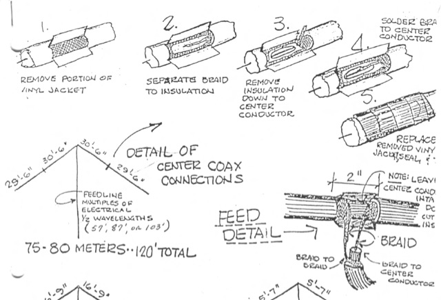
 This antenna is designed for 40, 80 and 160 meters to complement a tri-band beam normally taken on DX peditions for 10, 15 and 20 meters, so six bands can be worked with only two antennas.