Search results
Query: antenna 5 mhz
Links: 617 | Categories: 12
Categories
- Antennas > 40M > 40 meter Delta Loop Antennas
- Antennas > 40M > 40 meter Dipole Antennas
- Antennas > 40M > 40 meter Yagi Antennas
- Antennas > 6M > 6 meter Moxon Antennas
- Manufacturers > Antennas > VHF UHF Microwave > Microwave antennas
- Antennas > 20M
- Antennas > 23cm
- Antennas > 2M
- Antennas > 30M
- Antennas > 4M
- Antennas > 6M
- Radio Equipment > HF Vertical Antenna > Maldol MFB-300
-
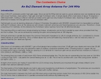
 W5GVE article on homebrewing a 144 MHz DDRR antenna for mobile use
 -
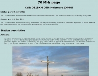
 146MHz 5/8 ground plane tower mounted antenna. The antenna was largely based information and analysis provided by the RSGB's. VHF UHF Manual, fourth edition by G.R.Jessop, G6JP
 -
-
 An experimental antenna similar to the TAK spiral antenna was evaluated for SWR response over the frequency range of 7.0 to 7.3 MHz, or the 40-meter band.
 -
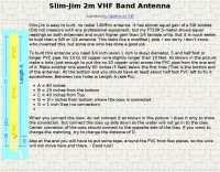 This VHF 145 MHz antenna is easy to build and with no radials. It shows equal gain of 5/8 lambda. It is light weight, you can hang it somewhere (on a tree may be) and work.
 -
 The Super J Pole antenna is a co-linear vertical consisting of a number of half wave length vertical elements separated with half-wave length stubs (Tuning stub) feed with a folded matching stub by vk6ysf
 -
-
 Manufacturer of Fibreglass Whip Antennas, Low and mediun Frequency, HF and VHF Antennas Specialized in the design and manufacturing of a full range of Beacon (MF), AM Broadcasting 540 - 1700 KHz, HF 1.7 to 30 MHz, VHF 30 to 156 MHz and UHF 200 to 500 MHz antennas.
 -

-
 The article "Exploring the World of 10 Meter Beacons" by Ken Reitz, KS4ZR, provides an in-depth look at 10-meter beacon operations, focusing on their utility for propagation analysis. It details FCC Rules part 97.203 governing beacon stations, including license requirements, power limits (under 100 watts), and the specified band segment of 28.200-28.300 MHz for U.S. operations. The content highlights the diversity in beacon construction, from converted CB radios to home-brew QRP transmitters, and discusses the robust operating conditions these 24/7 stations endure. The resource presents several case studies of active 10-meter beacon operators like Ron Anderson KA0PSE/B, Domenic Bianco KC9GNK/B, and Bill Hays WJ5O/B, detailing their equipment, antenna setups, and typical signal report volumes. It also introduces the NCDXF/IARU International Beacon Project, which features 18 synchronized beacons worldwide transmitting on 28.200 MHz at varying power levels (100W, 10W, 1W, 100mW) to facilitate propagation testing. The article also covers the PropNet Project utilizing PSK31 on 28.131 MHz and the 250 Synchronized Propagation Beacon Project on 28.250 MHz. Practical advice for monitoring includes using the RST reporting method, understanding the impact of the solar cycle on 10-meter propagation, and tips for setting up a personal beacon, such as frequency selection and power output considerations. The IY4M Guglielmo Marconi Memorial Beacon Robot on 28.195 MHz is also mentioned for its automatic QSO mode. The article concludes with a list of other resources for 10-meter beacon information.
 -
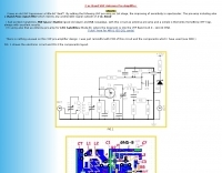 Electronic circuit and components layout fot this VHF Preamp
 -
 The G5RV antenna, a popular multi-band wire antenna, typically employs a center-fed design with a specific length of 300-ohm or 450-ohm open-wire line acting as an impedance transformer, feeding a coaxial cable run to the shack. Its overall length for 80-10 meters is approximately 102 feet (31 meters) for the flat-top section, with a 34-foot (10.36 meter) matching section. The original design by Louis Varney, G5RV, aimed for efficient operation on 14 MHz (20 meters) as a 3-half-wave antenna, with the matching section providing a good match to 50-ohm coax on that band. While the G5RV offers multi-band capability, its performance varies across bands, often requiring an antenna tuner for optimal SWR on bands other than 20 meters. The matching section's length is critical for its impedance transformation properties, influencing the feedpoint impedance presented to the coaxial cable. Variations like the G5RV Junior and ZS6BKW utilize different flat-top and matching section lengths to optimize performance for specific band sets or to achieve a lower SWR without a tuner on certain bands, demonstrating the adaptability of the basic G5RV concept.
 -
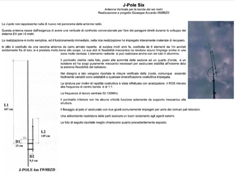 Homebrewed jpole antenna for 50 mhz by IW0BZD, include pictures and schematics, in italian.
 -
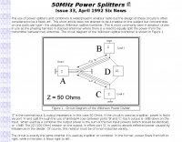 Splitting an antenna between two receivers or in use as the phasing harness in stacked antennas where there is a need to equally split the power from the transmitter between two antennas
 -
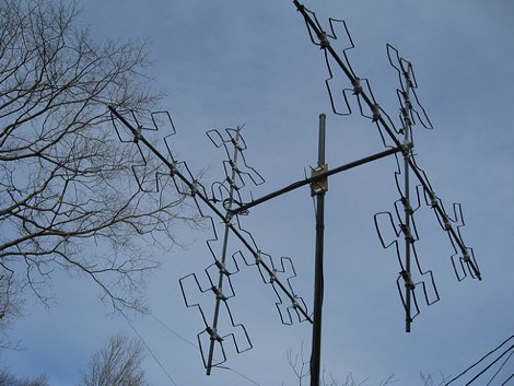 An experimental fractal Quad antenna for 10 meter band project by AG1LE
 -
 A simple drawing of a shortened antenna for 40 meters by using a PVC tube
 -
 A 7 elements yagi beam monoband antenna for 14 Mhz by VE3GK
 -
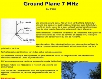 How to build a ground plane antenna for the 40 meters band in french
 -
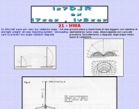 21 mhz half wave ant -very low radiation angle - full size and light weight- all coax matching system - decoupling care to prevent low angle radiation degrade
 -
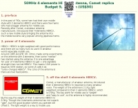
 A base station antenna you can easily build for 146,220 or 440 MHz, with performance similar to a J-pole but smaller and less obstrusive
 -
 A 144 MHz dipole antenna made from coax, PVC pipe, and aluminum foil tape
 -
 1/2wave vertical antenna for the 6-meterband and a 5/8 ground plane antenna for 50 Mhz
 -
 An homebrewed dipole antenna for 14MHz
 -
 This halo antenna was built to have an omnidirectional coverage while working in VHF contests.
 -
 Homebrew a 2 meter 1/4 wave vertical antenna for the 146 mHz ham radio band
 -
 Constructing a compact, two-band magnetic loop antenna for HF operation, especially from constrained locations like a balcony, presents unique challenges. OK1FOU's design, inspired by DJ3RW's 50 MHz loop, addresses these by employing an unusual side-fed configuration and placing the symmetric, two-section variable tuning capacitor at the bottom of the loop, directly connected to the coax shield. The article provides specific material recommendations, including two 1-meter wooden pales and about 3 meters of thick loudspeaker cable, noting the high current (60A at 100W) in the loop. Construction steps detail forming two turns with a 5 cm gap, using a GDO to pre-tune the open loop to a frequency slightly above the desired highest band, and then integrating the tuning and coupling capacitors. For 10/14 MHz, an open loop resonance of 16-17 MHz is suggested. Practical experience with the 10 MHz band from a third-floor balcony in Prague (JO70GC) shows a 1:1 SWR across most of the band without an external ATU. While DX traffic was modest due to the urban environment, QSO examples with RA6WF, LA6GIA, G0NXA, and LZ1QK on 10 MHz are provided, demonstrating its operational capability.
 -
 Constructing a Lindenblad antenna for 137MHz NOAA satellite reception involves specific design considerations for optimal performance. The resource details the use of 4mm galvanised steel fencing wire, 300-ohm television ribbon cable, and wood/plastic components for the antenna structure. Key dimensions for a 137.58MHz-resonant antenna are provided, derived from the ARRL Satellite Handbook, specifying s, l, w, and d as 42, 926, 893, and 654mm respectively. The antenna is designed for Right Hand Circularly Polarised (RHCP) signals, requiring the four folded dipole elements to be tilted clockwise by 30 degrees. A significant aspect covered is impedance matching between the antenna's 75-ohm impedance and a typical 50-ohm receiver input. A twelfth-wave matching transformer, constructed from 117mm sections of 50-ohm RG-58 and 75-ohm RG-59 coax with a 0.66 velocity factor, is described. The article also addresses coaxial cable and connector selection, recommending 75-ohm Type-N connectors for RG-6 cable in professional setups and F56/F59 connectors for general use, while strongly advising against PL-259/SO-259 connectors for VHF. Strategies for mitigating Radio Frequency Interference (RFI) are discussed, including antenna placement to shield from local TV transmitters and the use of commercial or DIY band-pass filters, such as cavity resonators or helical notch filters, along with ferrite chokes on coaxial cables. Antenna orientation is explored, noting the Lindenblad's 'cone of silence' directly overhead and its maximized sensitivity towards the horizon. An experimental vertical tilt of 90 degrees is presented as a method to improve overhead reception and reduce interference from strong horizontal signals, particularly relevant in high RFI environments like the Siding Spring Observatory site.
 -
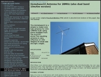 The Homebase10 is a simple to make wire halo antenna for 10m (28MHz) built using parts available from the local DIY store.The resulting antenna is very effective on 10m despite its small size and light weight.
 -
 Presents the design and construction of the OK2FJ Bigatas, a portable, automatically tuned vertical antenna covering 80 through 10 meters. It details two distinct control systems: one utilizing BCD band data from Yaesu FT-857/897 transceivers, and another employing voltage level sensing for the Yaesu FT-817. The resource provides specific instructions for building the antenna's radiating element, loading coil with switchable taps, and the control circuitry, emphasizing the use of readily available components. The article outlines the physical construction of the antenna, including the use of duralumin tubes for the radiator and a PVC tube for the coil form. It specifies coil winding details, tap points, and the integration of radial wires for ground plane operation. The control electronics section provides schematics and component lists for both the BCD decoder (using a 74LS42 IC) and the voltage comparator (using an _LM3914_ bargraph driver), enabling rapid, automatic band switching without the minute-long tuning delays common in other systems. Crucially, the antenna achieves rapid band changes, with typical SWR values centered on common operating segments, such as **3.7 MHz** for 80m SSB. It also discusses modifications for CW operation on 80m and the trade-offs between antenna efficiency and full-range automatic tuning on higher HF bands, where manual adjustment of radiator length is suggested for optimal performance on 15m, 12m, and 10m. The resource includes construction photos and a discussion of cable requirements for reliable operation.
 -
 JJ0DRC's HF multi-band delta loop antenna project, initially conceived during the waning peak of Cycle 23, addresses the common challenge of achieving effective DX operation from a small residential lot in Japan. Dissatisfied with a ground plane antenna's performance in SSB pile-ups, the author sought a beam-like solution without a tower, drawing inspiration from a JJ1VKL article in CQ Ham Radio Sep. 2000. The antenna, constructed in October 2000, employs two 7.2-meter fishing rods (37% carbon fiber, reinforced with cyano-acrylate glue and aluminum tape) and 1mm enameled wire, fed by an Icom AH-4 external antenna tuner. While the exact beam pattern remains unmeasured, JJ0DRC observed a significantly higher callback rate compared to dipole antennas, particularly on higher bands. The system's circumference length of 15-20m is crucial for maintaining a good beam pattern across HF bands, though performance on lower bands like 80m, 40m, and 30m becomes less directional as the length deviates from a full wavelength. Ongoing maintenance addressed degradation issues, including aluminum tape cracking and wire breakage at connection points due to strong winds (often exceeding 10-15m/s in winter). The author reinforced rod connections with IRECTOR PIPE SYSTEM components and INSU-ROCK ties, and improved wire attachment methods using Cremona rope and epoxy bond to enhance durability.
 -
 This resource details the computer-optimized design of the _ZS6BKW_ multiband dipole, an evolution of the classic _G5RV_ antenna. It begins by referencing the original 1958 RSGB Bulletin article by Louis Varney G5RV, explaining the operational principles of the G5RV's flat-top and open-wire feedline on 20m and 40m, noting its impedance transformation characteristics for valve amplifiers of that era. The article then transitions to the rationale for optimizing the design for contemporary solid-state transceivers requiring a 50 Ohm match. The core of the project involves using computer modeling to determine optimal lengths for the flat-top and matching section, aiming for a VSWR of less than 2:1 on multiple HF bands. It discusses the process of calculating feedpoint impedance based on antenna length and frequency, referencing professional literature from Professor R.W.P. King at Harvard University. The analysis also considers the characteristic impedance (Z(O)) of the open-wire line, identifying a broad peak of adequate values between 275 and 400 Ohms. Specific design parameters for the improved ZS6BKW are presented, including a shorter flat-top and a longer matching section compared to the original G5RV, with a velocity factor of 0.85 for the 300 Ohm tape. The article confirms acceptable matches on 7, 14, 18, 24, and 28 MHz bands when erected horizontally at 13m, and also discusses performance in an inverted-V configuration, noting frequency shifts. The author, Brian Austin ZS6BKW, emphasizes the antenna's suitability for modern 50 Ohm coaxial cable without a balun.
 -
 This antenna was designed to meet the requirements of a light body worn small magnetic loop covering all the frequencies continuously from 7 MHz to 29.4 MHz
 -

-
 Solution to your OEM needs and can meet your design or vended antenna requirements for antennas from 400MHz to 10 GHz.
 -
 VHF Optimized Yagi Antenna for the 6-meter band (50 Mhz) by ON6MU
 -
-
 7.5 MHz wideband audio delivered via AMC-7 satellite transponder 5 provides a robust platform for disseminating amateur radio news. This service caters to operators seeking timely updates on regulations, technology, and DX news. The bulletin is accessible in both MP3 and RealAudio formats, ensuring compatibility with a wide range of devices and listening preferences. Regularly updated content keeps amateur radio enthusiasts informed about the latest developments in the hobby. The service covers a broad spectrum of topics, including contesting, digital modes, and antenna technology. By leveraging satellite and internet distribution, it reaches a global audience, making it a vital resource for operators worldwide. Listeners can expect a consistent flow of information, with new episodes released frequently. The service's commitment to providing high-quality content ensures that amateur radio operators remain well-informed and engaged with the community.
 -
 By ON4CFC Pascal, describe how to build a Sperrtopf or Sleeve antenna for the 144 Mhz, PDF File by antennex
 -

-
-
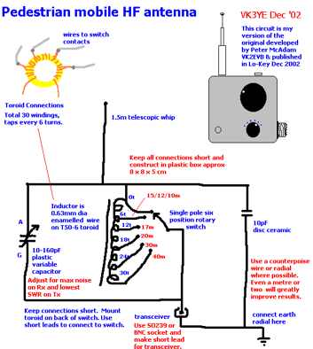 This antenna allow transmission and reception on all bands between 7Mhz and 28 Mhz. Similar in concept to the Miracle Whip by VK3YE
 -

-
 Two 50 Mhz amplifiers and antenna switch
 -
 This article describes the design of an antenna for local contacts on 7MHz, including a simple and efficient matching system that presents a 50 ohm load to the transceiver.
 -
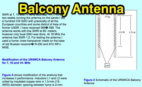 A project for a balcony antenna that works on 7 10 14 MHz made by 2 PVC tubes coiled with insulated copper wire, a solution for restricted lots.
 -
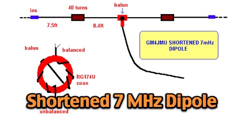 A shortened 7 MHz Dipole antenna as described by Ken GM4JMU in Sprat 74.
 -
 This note describes a relatively small, but efficient, loop antenna initially created for portable operation. With suitable modifications, it can be adapted for fixed station use. In this age of CC&Rs, an antenna similar to this may very well be the answer to your problems. Have a look, be inspired, get out the torch / soldering iron and create your own version!
 -
 The Grid Yagi (or Grid Quad) is a high performance yagi antenna that can be built with readily obtainable inexpensive materials. Described here is a 6 element 2 meter version with a boom length of about 1 wavelength, shown
 -
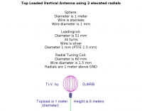 A 3.5 Mhz top loaded vertical antenna built using 2 elevated radials by DJ9RB
 -
 Demonstrates the construction of two distinct wideband RF preamplifiers, detailing their component requirements and performance characteristics. The first design leverages monolithic microwave integrated circuits (MMICs) such as the MAR-6, MAR-8, or PGA103, offering a broad frequency response from DC to 2 GHz with a gain of 22.5 dB at 100 MHz and a noise figure typically below 3 dB. This MMIC-based amplifier incorporates protection against power supply transients and features a 50 Ohm input/output impedance, operating from an 8-20 volt supply with low current drain. The second preamplifier design utilizes a BSX-20 transistor, providing amplification across the 14 MHz to 550 MHz range. This simpler, more economical build achieves an average gain of 12 dB at 145 MHz and a noise figure of approximately 1.1 dB. It operates from a 7-15 volt battery supply with a current draw of 6 mA. Both projects emphasize critical construction techniques, such as maintaining short RF connections, ensuring 50 Ohm impedance paths, and mounting the circuit within a shielded enclosure to optimize performance and minimize noise. The resource also discusses phantom power options for antenna-mounted preamplifiers and precautions for use with transceivers, including output protection diodes and static bleeders.