Search results
Query: eme antennas
Links: 222 | Categories: 2
-
 Operating an amateur radio club, VE2CEV details its activities, including regular meetings and a significant project involving the construction of a **satellite ground station**. The resource outlines the project's inception, team formation, equipment acquisition, and the physical installation of antennas and rotator systems. It specifically mentions the use of a dual-axis AZ/EL rotator and antennas for VHF, UHF, and SHF (2 meters, 70 centimeters, and 13 centimeters), along with the strategic use of **Heliax cables** to minimize RF signal loss. The club also provides information on its interconnected repeater network covering southwestern Montérégie. The content highlights the practical application of the satellite station for communicating via amateur satellites and the International Space Station (ISS). It details the collaborative effort of members in securing a powerful Linux server, negotiating antenna installation with local authorities, and the precise alignment of antennas. The club emphasizes its role in guiding new amateurs, offering demonstrations, and potentially organizing courses, indicating a focus on community engagement and technical education within the amateur radio hobby.
 -
 Antennas for the 1296 MHz based on the construction plans of some Yagis 35 elements by DL6WU, F9FT, DJ9YW. These antennas features a boom of about 3 m and gives a gain of about 17.8 dBd
 -
 High Speed Multimedia (HSMM) radio, as introduced by John Champa, K8OCL, represents a significant advancement in amateur radio's digital capabilities, moving beyond traditional keyboard modes like packet radio. This initiative, driven by ARRL's Technology Task Force, focuses on developing high-speed digital radio networks capable of up to 20 megabits per second. HSMM primarily facilitates digital voice (DV) and digital video (ADV), enabling real-time video transmission from emergency scenes to an EOC without expensive ATV gear, often requiring only a laptop, a PCMCIA card, a digital camera, and a small antenna. The working group's initial efforts concentrate on cultivating microwave skills within the amateur community to build and support portable and fixed high-speed radio-based local networking, or **RLANs**. These networks prove invaluable for RACES and ARES organizations, as well as homeland security and other emergency communications. Field Day exercises and simulated emergency tests (SETs) are encouraged to hone skills in rapid site surveys and deploying broadband HSMM microwave radio networks, with examples like linking Field Day logging stations or antenna test results at the Midwest VHF-UHF Society Picnic 2003. Getting started with HSMM often involves adapting off-the-shelf **IEEE 802.11** (WiFi) equipment to comply with amateur radio regulations, typically operating in the 2.4 GHz ISM bands. While consumer WiFi gear has range limitations under Part 15 rules, proper setup under amateur regulations can extend coverage significantly, with test networks like the Hinternet achieving 5-15 mile ranges at 54 M bit/s using small mast-mounted dish antennas. Careful selection of equipment with external antenna ports, high transmit power, and low receive sensitivity is crucial, along with using low-loss coaxial cable like LMR-400 for optimal performance at these frequencies.
 -
 The "DIY Telescopic-V Antenna £35" project showcases the creation of a budget-friendly, portable telescopic V-shaped antenna inspired by commercial designs. Using eBay-sourced telescopic whips and custom mounting solutions, the author documents their process, testing, and adaptations. Despite challenges like weather and missing tools, the antenna performed well across multiple bands, enabling successful QSOs. Future improvements include exploring loading coils and testing in better locations. The compact design offers versatility for amateur radio enthusiasts seeking an affordable and practical solution.
 -
 Operating in a Single Operator Two Radios (SO2R) setup, especially with beverage antennas, often exposes the receiving radio's front-end to significant RF energy from the transmitting radio. This resource details a practical, homebrew receiver protection circuit designed to mitigate this risk. The core of the design involves a non-inductive 2W 22 Ohm carbon composition resistor in series with the RX antenna line, followed by two stacks of four fast-switching diodes (e.g., _1N914_) configured in opposite polarizations. This arrangement effectively clamps the incoming voltage to approximately 2.8 V peak-to-peak, safeguarding sensitive receiver input components. The series resistor plays a crucial role by absorbing excess power, preventing the diodes from exceeding their current ratings and potentially failing open, which would leave the receiver unprotected. The author, _N4KG_, measured up to 50 watts of coupled power between 80M slopers on the same tower, highlighting the necessity of such protection. The design is presented as a cost-effective solution to prevent damage to receiver input transformers, with the author noting successful protection of a receiver even after a resistor showed signs of overheating. This simple circuit can be integrated via a transverter plug, offering a robust defense against high RF input.
 -
 An FCP is not magic. It has no gain. An FCP improves an antenna system by replacing more loss with less loss. Some have been able to erect better wires in the air because the small size of the FCP allowed better placement of the antenna.
 -
 10 Elements Cross-Yagi Antenna for 433 MHz. The base of the 10el antenna is the recalculated RA6FOO antenna.Circular polarization is realized - by a phasing quarter-wave line, matching of horizontal and vertical polarization antennas
 -
 Operating in antenna-restricted communities presents unique challenges for amateur radio operators, often necessitating creative solutions for antenna deployment. This resource details the design and implementation of stealth antennas within a townhouse community in Exton, PA, where external antennas were strictly forbidden by covenants. The author, WB5NHL, describes his setup, which involved locating the shack in the basement and utilizing an unused space under the roofline of a finished third-floor loft for antenna placement. The content specifically addresses the practicalities of routing coax cables three floors and maximizing antenna performance within limited attic space. It covers solutions for multi-band operation, including dedicated sections for 40-10 meter and 80-meter antennas, along with strategies for mitigating potential interference issues. The approach emphasizes full compliance with community covenants, achieving maximum height-above-ground for horizontal antennas, enabling instant band switching, and efficiently utilizing available attic volume. While acknowledging limitations such as potential interference with high power and fixed antenna patterns, the resource provides a detailed account of a functional compromise for restricted environments. Links to individual pages on _coax cables_, _40-10 meter antennas_, _80-meter antennas_, and _interference issues_ offer deeper dives into each specific aspect of the installation.
 -
 German antenna parts dealer, provides antenna element holders, element clamps for yagi antennas, junction boxes, aluminium plates and rods. Offers also Rope tensioners, plugs and adapters and any additional part you need when you want to make your own antenna.
 -
 A hexagonal beam is a form of the Yagi antenna which is based on parasitic principles developed early in the last century in Japan for achieving gain in one direction.How HexBeam antennas works. A hexagonal beam operates exactly like Yagi antenna, but instead of a driven element that is straight like a dipole, it is a wire bent into the shape of the letter M.
 -
 The PAC-12 Antenna, a multi-band portable vertical, is meticulously detailed in this construction article by James Bennett, _KA5DVS_. The design emphasizes ease of homebrewing using readily available components from local hardware stores, including replaceable loading coils. It outlines the preparation of the 72-inch telescoping whip (originally from Radio Shack, with an alternate source now provided by _Pacific Antenna_), the construction of the loading coils from PVC risers, and the fabrication of the aluminum rod base sections. Specific instructions cover threading aluminum rod with a _1/4-20 threading die_ and assembling the feedpoint insulator with a BNC connector, along with recommendations for radial deployment. KA5DVS, an avid traveler and QRP enthusiast, developed the PAC-12 to address the bulkiness of random wire setups and the limitations of commercial portable antennas like the Outbacker or SuperAntennas MP1. His goal was a lightweight, packable antenna that disassembles into 12-inch sections, achieving an assembled length of approximately 8 feet. The design strategically places the loading coil away from the base for improved efficiency. The PAC-12 notably placed first in efficiency compared to a quarter-wavelength wire vertical at the HFPack antenna shootout during the Pacificon conference in October 2001, demonstrating its practical performance for field operations. Appendix C showcases various _NJQRP Club_ members' PAC-12 constructions, including a 20m beam made with multiple PAC-12 elements.
 -
 This tutorial provides detailed instructions for constructing a DIY magnetic loop antenna, ideal for amateur radio operators seeking efficient short wave communication. The design features a remote tuning system utilizing an Arduino and RC servo, making it suitable for indoor use where larger antennas cannot be installed. Magnetic loop antennas are compact and can operate effectively in confined spaces, but they do require careful handling due to the high voltages and currents they generate during operation. Users should possess the necessary technical skills to implement this project safely. The tutorial includes a comprehensive overview of the antenna's theory, specifications, and mechanical design. It outlines the components needed, including a Soviet-made variable capacitor and a digital RC servo for tuning. Safety precautions are emphasized, as the antenna can produce several kilovolts of voltage and high currents. The project is not certified for safety, and users are advised to proceed at their own risk. The tutorial also provides diagrams and explanations of the antenna's operation, making it a valuable resource for both beginners and experienced operators looking to enhance their setup.
 -
 Hy-Gain TH3jr Tri-band HF 3 Element Beam Covers 10, 15 and 20 Meters assembly instruction manual
 -
 This blog post details the construction and usage of a 4:1 current balun, using two FT240-31 ferrite cores and 12 bifilar turns. It clarifies common misconceptions about using 4:1 baluns with G5RV antennas and ladder-line to coaxial cable connections. M0PZT emphasizes the importance of proper measurements and the limitations of internal baluns in manual antenna tuners. Detailed instructions and considerations for winding and deploying the balun are provided, along with advice on choosing suitable cores and wire for various power levels and frequency ranges.
 -
 LZ1AQ describes a versatile QRP antenna tuner that switches between Pi and Tee configurations with a single toggle. Using two variable capacitors and a seven-switch stepped inductor providing 128 increments (0.16 to 18.7 uH), this compact design handles 3.5 to 28 MHz with excellent matching range. The Pi mode works best for certain impedances while Tee mode proves more universal, matching loads the Pi cannot. Built in a plastic enclosure using salvaged radio capacitors, the tuner operates reliably up to 100 watts with proper antennas, though it's optimized for QRP service with random wires.
 -
 The _G3TSO_ Mobile Antenna Page details construction and tuning methods for mobile antennas operating across **10 to 160 metres**. The content describes a Hustler-based design, optimized for RF performance and vehicle speeds, featuring centre loading. For optimal operation on various bands, the loading coil placement requires clearance from the vehicle body. Antenna resonance is critical for efficient mobile operation. A mobile antenna's base impedance may be as low as 27 ohms, requiring specific matching to achieve maximum radiation, as a minimum SWR at the transmitter does not always indicate resonance or maximum output. Tuning involves physical adjustment of antenna length to achieve resonance at the operating frequency. The _G3TSO_ page outlines a tuning procedure utilizing a low-power signal source and a field strength meter to identify maximum radiation before impedance matching. Loading coil placement, either at the base, center, or top of the antenna, influences radiation efficiency and mechanical stability for mobile installations. Centre-loaded whips, such as the Hustler design, offer a compromise between efficiency and stability, often for single-band operation. Helically wound antennas, including those for **28 MHz**, may present base impedances around 17 ohms, resulting in a 3:1 SWR at resonance. Low resistance grounding at the antenna base is also specified for optimizing performance and minimizing RFI during mobile operation. DXZone Focus: Mobile | Any | Antenna Tuning | HF
 -
 Learn how to easily improve your handheld VHF performance on the 2-meter band with the Flowerpot antenna. This simple DIY antenna made from coaxial cable requires minimal tools and materials, providing a big range upgrade compared to standard rubber-duck antennas. Discover how to build, tune, and optimize the Flowerpot antenna for excellent performance. Ideal for hams looking for lightweight, portable solutions for handhelds, mobile rigs, home stations, SOTA/POTA activations, and emergency communication.
 -
 This is a remote antenna switch I use in my attic to connect transceivers in the basement to multiple antennas in the attic. The goal of this project is to be able to remotely connect one of the antennas in the attic to the only antenna cable available.
 -
 This page presents an online calculator tool for determining the dimensions of various HF wire antennas operating between 1.8-30 MHz. Users input their desired resonant frequency to obtain precise measurements for four popular antenna types: standard flat-top dipole, inverted Vee, quad loop, and equilateral delta loop. The calculator provides comprehensive measurements including leg lengths, minimum heights, horizontal spreads, and feedpoint distances. Accompanying the calculator are detailed technical explanations, construction notes, and installation guidelines for each antenna type, making it a practical resource for amateur radio operators building their own antennas.
 -
 Learn about the practical design and construction of Yagi antennas for ham radio operators. This post explores the benefits of Yagi antennas in receiving and transmitting RF signals, concentrating signal energy in one direction for long-distance communication. Discover the theory behind Yagi antennae, the importance of element size and spacing, and the resources available for sizing and construction. Whether you're interested in OTA television or amateur radio communication, understanding Yagi antenna design can enhance your signal reception and transmission capabilities.
 -
 Operating within the low-frequency spectrum, transformers serve critical roles in antenna systems, particularly for 160m applications. The resource details the construction and performance of 1:1 transformers built on BN-73-202 cores, emphasizing their use as hybrid combiners or phase inverters for RX antenna arrays. Measurements reveal that these transformers exhibit minimal losses, around 0.12 dB at 1.8 MHz, with variations based on wire type and number of turns. The analysis includes comparative data on transformer performance, highlighting the impact of different winding techniques on frequency response. Notably, the use of coaxial cable for winding improves bandwidth while maintaining low-frequency efficiency. The resource also discusses braid breaker transformers, which minimize inter-winding capacitance, achieving low losses around 0.21 dB at 1.8 MHz. These insights are crucial for optimizing low-band antenna systems, allowing operators to make informed decisions regarding transformer design and implementation.
 -
 This document provides a detailed guide on constructing and mounting a folded dipol for the 146 MHz frequency in a vertical configuration to be used in Yagi antennas. The step-by-step instructions and diagrams included make it easy for hams to build and set up this type of antenna. Understanding and implementing this design can enhance the performance of radio communication for Amateurs operating in the 2-meter band. Whether you are looking to improve your signal strength or experiment with antenna designs, this resource offers valuable insights and practical information.
 -
 This antenna is designed for 40, 80 and 160 meters to complement a tri-band beam normally taken on DX peditions for 10, 15 and 20 meters, so six bands can be worked with only two antennas.
 -
 Hamradio_copilot is an open-source tool designed for DXers and contesters who need real-time situational awareness. It is ideal for operators who want to visualize propagation trends instantly rather than scrolling through raw text streams of cluster spots. Rally acting as a copilot for your station, this tool transforms raw data into actionable intelligence. By visualizing Signal-to-Noise Ratios (SNR) across different bands, it helps operators make quick decisions on which band to prioritize or where to point their antennas, effectively showing not just who is on air, but where the propagation is currently open from your location. This is a fantastic information for avid contesters. The software aggregates data from two primary services: - Reverse Beacon Network (RBN) via Telnet. - PSK Reporter via MQTT feeds. It processes this data to generate a comprehensive HTML report featuring SNR heatmaps and statistical breakdowns by ITU Zone. Users can filter data by specific zones or country codes (ADIF), analyze historic time ranges, and optionally integrate solar weather data. The complete source code is available on GitHub, allowing for community customization. It is written in Python and uses SQLite for data management.
 -
 A 14.12 dBi gain three elements cubical quad antenna for the six meters band. This Quad Antenna design page include a MMA model available to download and dimensions for each element.
 -
 In this article the author describes his personal experience on some antennas for 50 MHz he tested on the field, the six meter Dipole, Vertical, Moxon, a 3 element Yagi and an Omniangle antenna.
 -
 This study details a reception comparison between vertical and horizontal active loop antennas, specifically two identical _Wellgood active loop antennas_, on various HF bands. The experiment, conducted in a densely populated QRM-prone area, monitored FT8 signals over a 24-hour period using two identical receivers. The methodology involved direct comparison of signal reception across the HF spectrum, aiming to identify performance differences based on antenna orientation. The results indicate that vertical loops demonstrated superior performance on higher bands (10m, 15m, 20m), while horizontal loops excelled on lower bands (30m, 40m, 160m), particularly for receiving long-distance (DX) signals. The horizontal loop's advantage on lower bands is attributed to potentially better low-angle performance and reduced sensitivity to man-made noise, yielding a **2-3 S-unit** improvement on 160m. The study provides practical insights for optimizing antenna placement in challenging urban environments, noting that the horizontal loop consistently showed a **10-15 dB** signal-to-noise ratio improvement on lower bands.
 -
 This Satellite Antenna Elevation System project involves mounting horizontally polarized Yagi antennas on a fiberglass reinforced polymer (FRP) crossboom. A Yaesu G-800DXA azimuth rotator is in place, requiring only an elevation rotation system. Elevation is controlled by a 12VDC linear actuator connected to a U-bolted arm on the crossboom, rotating within a DIY bearing arrangement. Common handyman tools suffice for assembly. The setup includes FRP crossboom, aluminum tubing, PVC couplers, nylon camshaft bushes, and a K3NG-based controller for azimuth and elevation control. Detailed guides and resources are available online.
 -
 Constructing an effective antenna support system often involves safely elevating wire antennas into trees or over obstacles. This resource details the build process for the WT8WV "Colossus" air cannon antenna launcher, a pneumatic device designed to project a pilot line over elevated structures. It specifies the use of readily available PVC pipe components and standard hardware, outlining the exact materials required and providing step-by-step assembly instructions for a robust, low-cost solution. The article presents a practical alternative to traditional methods like slingshots, emphasizing the launcher's utility for Field Day operations and general antenna deployment. It includes a comprehensive list of parts, such as 2-inch and 1-inch PVC pipe, various fittings, a sprinkler valve, and a bicycle pump valve, detailing their integration into the final assembly. The total cost for materials is estimated at around $40 per unit, making it an accessible project for many radio amateurs. Crucially, the guide incorporates essential safety precautions for operating a pneumatic launcher, covering aspects like pressure management and projectile selection. It also features multiple photographs illustrating the construction phases and the completed device, offering visual clarity to aid builders in replicating the design.
 -
 Learn how to build wire Yagi antennas for your ham radio setup. Discover how smaller wire elements can offer practical and portable options for temporary operations. Explore designs like the Hex Beam, Spider Beam, and Moxon that require less mechanical complexity and can be easily rotated or supported. Find out how to construct and hang wire Yagis from ropes, trees, or masts with inverted vees or horizontal elements. Get tips on element positioning, gain, and beamwidth considerations. Follow simple construction steps using a rope boom and marking element positions for efficient assembly. Enhance your ham radio experience with versatile wire Yagi antennas.
 -
 This DIY guide details constructing a 5-element Yagi antenna for VHF frequencies. Yagi antennas offer directional signal transmission/reception compared to omnidirectional ones. The guide covers material selection (aluminum, screws, etc.), design using software or formulas, and step-by-step assembly including cutting elements, drilling holes, and attaching the coaxial cable. While calculations are provided for a 146 MHz design, adjustments are necessary for different frequencies. Safety precautions and potential result variations are emphasized.
 -
 This project introduces the Loggi, a hybrid antenna merging the wide frequency coverage of log-periodic dipole arrays (LPDA) with the high gain and front-to-back ratio (F/B) of Yagi antennas. Traditional LPDAs span broad frequencies with moderate gain and low VSWR, while Yagis provide high gain and F/B over narrow bands. By analyzing high-Tau LPDA designs, it was found they could nearly match the gain of VHF/UHF Yagis while maintaining excellent patterns, F/B, and front-to-rear ratios (F/R). Optimizing specific elements for target frequencies (e.g., 144.1 MHz) led to the Loggi, which uniquely features all driven elements without passive directors or reflectors. This design effectively functions as a narrowband optimized LPDA, with front elements acting like Yagi directors and rear elements like Yagi reflectors, thus enhancing gain and directional characteristics while retaining broad frequency versatility.
 -
 A 5/8 λ antenna, often thought to be ideal for all frequencies, has unique characteristics that don't universally apply. First introduced for medium-wave radio, it works optimally at 225° antenna length over ideal ground, yielding high efficiency. However, at VHF and higher frequencies, it offers no advantage over other antennas due to real ground conditions and complex matching requirements. DIY calculators provide only rough estimates, useful as a starting point for simulations, not for precise builds.
 -
 Showcasing German engineering, ANjo Antennen develops and manufactures a diverse portfolio of amateur radio and commercial antenna products. Their offerings span a wide frequency range from 1.8 MHz to 3000 MHz, emphasizing electrical and mechanical precision for longevity. The company actively participates in events like FUNK.TAG Kassel, providing opportunities for direct engagement and order pickup. ANjo's product line includes high-performance **Yagi antennas** optimized for Tropo and EME, along with multi-stacked Quad antennas designed for contest operations, featuring wide horizontal and narrow vertical beamwidths. They also produce circularly polarized satellite antennas, some with switchable LHCP/RHCP, leveraging their commercial satellite antenna expertise. Beyond amateur applications, ANjo provides flexible, custom antenna solutions for commercial sectors such as BOS, EMC measurements, and telemetry. Their commitment to quality is evident in the Premium-Line antennas, which utilize **1.4301 (V2A) stainless steel** for mast clamps and connectors, ensuring durability and corrosion resistance. They also offer end-fed HF multiband wire antennas, known for their compact footprint and discreet installation.
 -
 This page provides information on designing a lightweight Moxon antenna for the upper HF bands and VHF. The Moxon antenna is a compact version of a 2-element Yagi with folded elements, offering good forward gain and a high front-to-back ratio. It is designed for a single band with a feed-point impedance close to 50 ohms. Hams can orient the antenna horizontally or vertically, with polarization following the configuration, affecting radiation patterns. The page allows users to generate radiation pattern plots, VSWR charts, antenna currents diagrams, and Smith charts for their antennas on different ground types, helping them understand antenna performance in the field.
 -
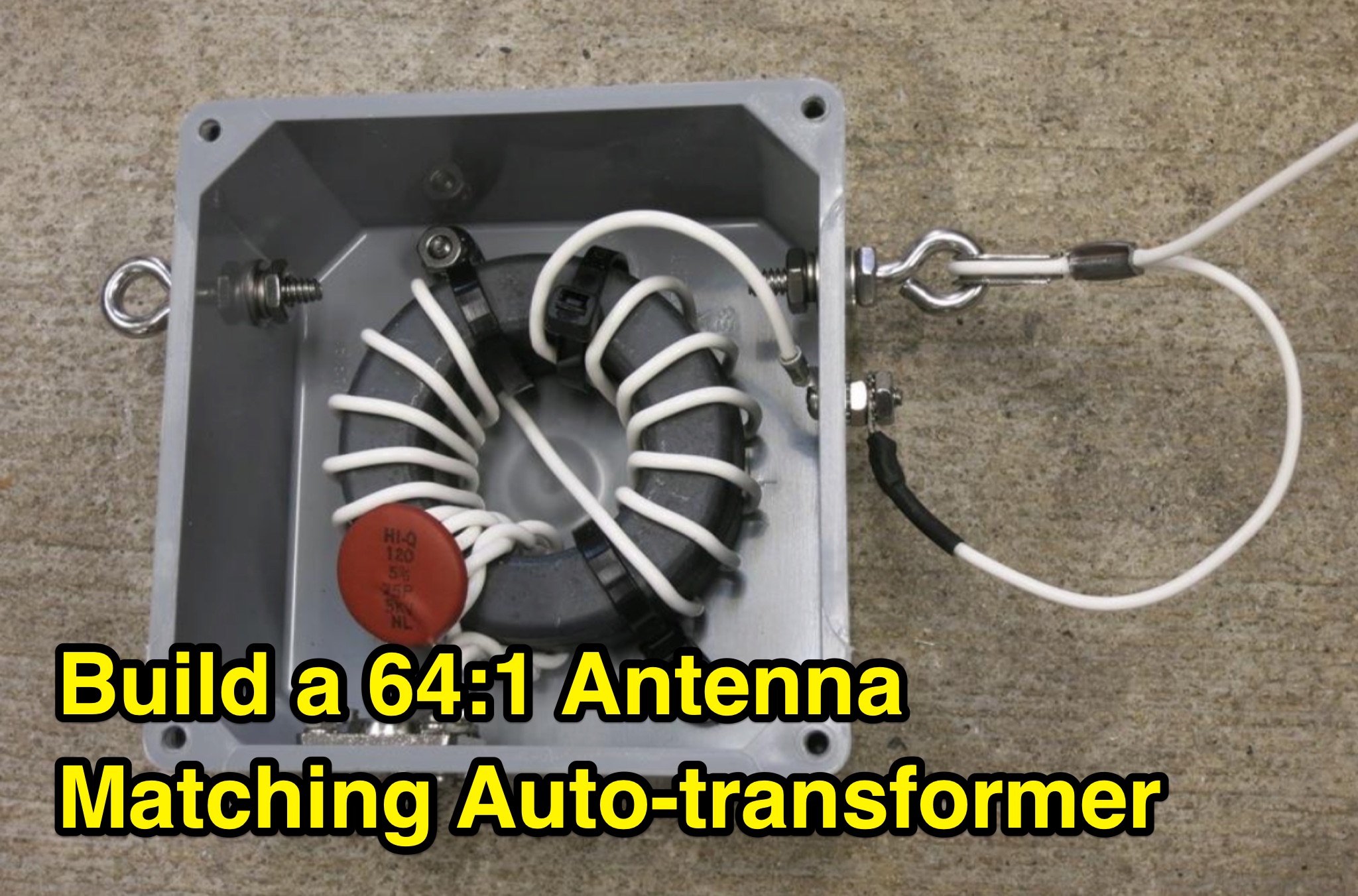 This PDF document provides information on a 64 to 1 antenna matching auto-transformer for ham radio operators. It likely includes details on how to build or use this specific type of antenna matching device, which can be helpful for hams looking to optimize their antenna setup. The document may contain technical specifications, diagrams, and instructions on how to properly implement the auto-transformer. Overall, it serves as a useful resource for hams interested in improving their antenna performance and signal transmission.
 -
 This page provides construction details for a 4-element 10-meter Yagi antenna with 28 Ohm impedance. It includes information on the elements, positions, diagrams, and data related to frequency, gain, front-to-rear ratio, radiation resistance, SWR, and loss. The content is aimed at hams or radio operators interested in building and optimizing Yagi antennas for the 10-meter band.
 -
 Method, Units of Measure, and the Dipole Standard of Reference. This article helps in understanding where does beam gain come from in directional aerials like in example Yagi antennas.
 -
 The PA0FRI Unbalanced/Balanced ATU is a home-built antenna tuner designed to efficiently match a W8JK 2-element beam antenna fed with a 450-ohm twin lead. Based on PA0FRI’s S-Match design, it optimizes energy transfer while maintaining balance, reducing losses, and ensuring proper radiation. The tuner uses a roller inductor, air variable capacitors, and a T200 iron powder coil, allowing fine-tuning across 14-50 MHz. Extensive lab tests confirm minimal attenuation and precise impedance matching, making it a reliable and efficient ATU for balanced antennas.
 -
 This page delves into the debate surrounding the End-Fed Half-Wave (EFHW) antenna, exploring whether it is truly a multiband antenna without the need for a tuner. The author investigates the claims and criticisms surrounding these popular antennas, discussing their resonance on various bands and their efficiency for DXCC achievements. The content is valuable for hams interested in understanding the capabilities of EFHW antennas and their performance across different HF bands, with a focus on practical usage and real-world results.
 -
 This article details the development of an 80-meter antenna within the confines of a restrictive covenant community. Faced with limited space, the author explores various options before implementing a clever hybrid design: a short 30-foot vertical wire running discreetly down the building's exterior combined with a capacitive top hat installed in the attic. Computer modeling confirmed the superiority of capacitive loading over inductive loading, increasing radiation resistance from 6 to 14 ohms. The perimeter wire top hat, naturally supported by the attic structure, resonates effectively at 3.5 MHz. The system is completed with four buried 60-foot radials installed "after dark" to maintain compliance with community restrictions.
 -
 Delta loop antennas, particularly the 30 meter variant, offer unique advantages in terms of vertical polarization and omni-directional coverage. The construction process detailed by VE3VN highlights common mechanical and electrical challenges faced by amateur radio operators. Key design considerations include minimizing interaction with existing contest band antennas, achieving low elevation angles for DX chasing, and ensuring the antenna remains off the ground for agricultural clearance. The article provides specific measurements, such as the loop's height and feed point impedance, which are critical for optimizing performance. The use of NEC modeling software illustrates the importance of accurate resonance calculations, revealing how proximity to the tower affects both pattern and impedance. This practical account serves as a resource for hams looking to build effective antennas while navigating typical construction hurdles.
 -
 This article provides a cost-effective and reliable method for fixing antenna elements in the traverse of HF/UHF Uda-Yaga antennas. It outlines a step-by-step process using soft galvanized steel wire, eliminating the need for special adapters or additional holes. The method described ensures a secure attachment without compromising the mechanical strength of the traverse, offering a durable solution for ham radio operators constructing antennas. The use of galvanized steel wire guarantees long-lasting stability, making it a practical and efficient technique for antenna assembly.
 -
 Phased array antennas are composed of multiple individual antenna elements that can have their phase and amplitude controlled to steer the main beam direction in real-time. They are used in radar, communications, and electronic warfare, and offer improved gain and reduced side lobes. A comprehensive document on Phased Arrays include techniques to increase the Antenna Gain and change the Radiation Pattern
 -
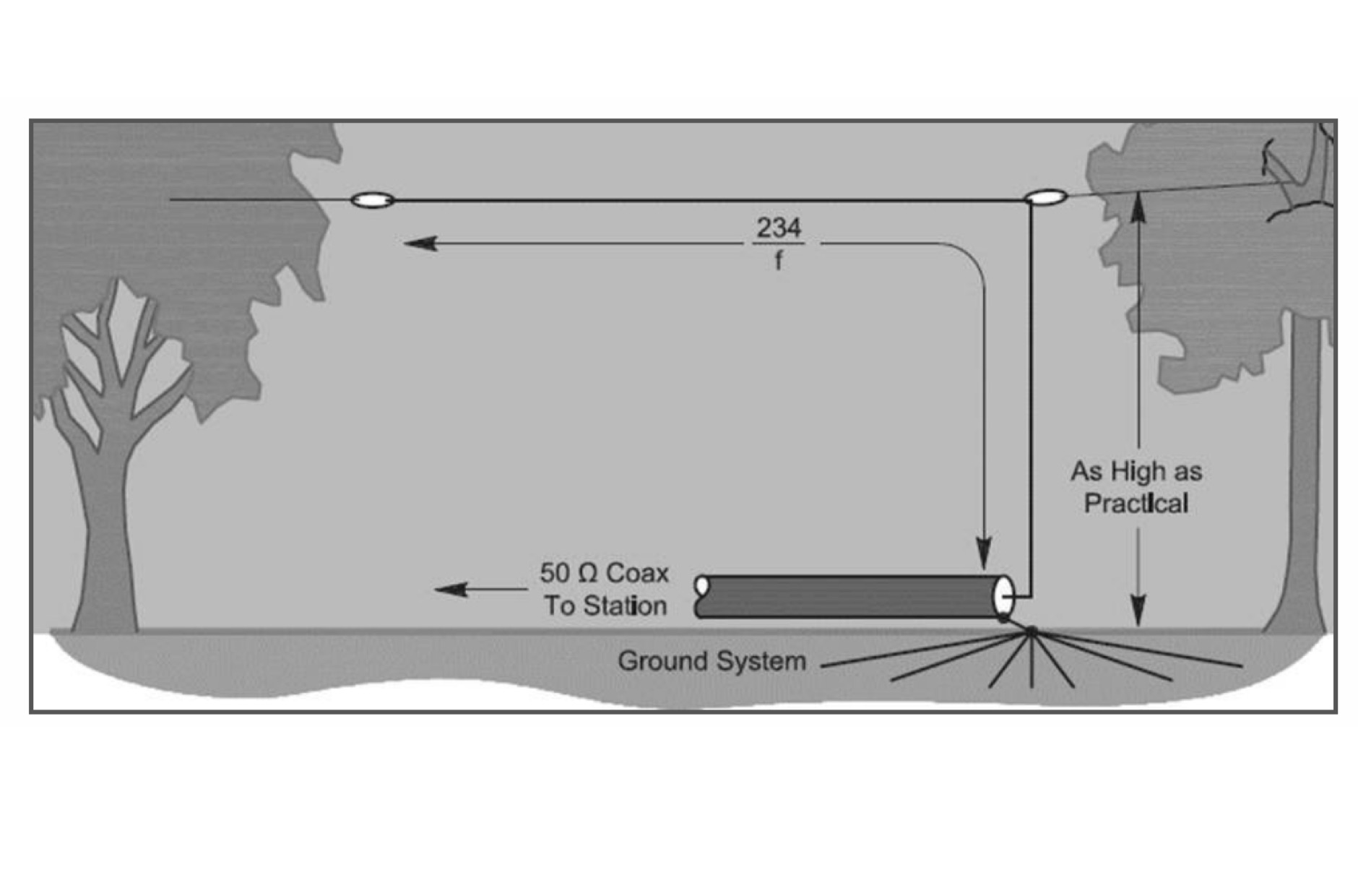
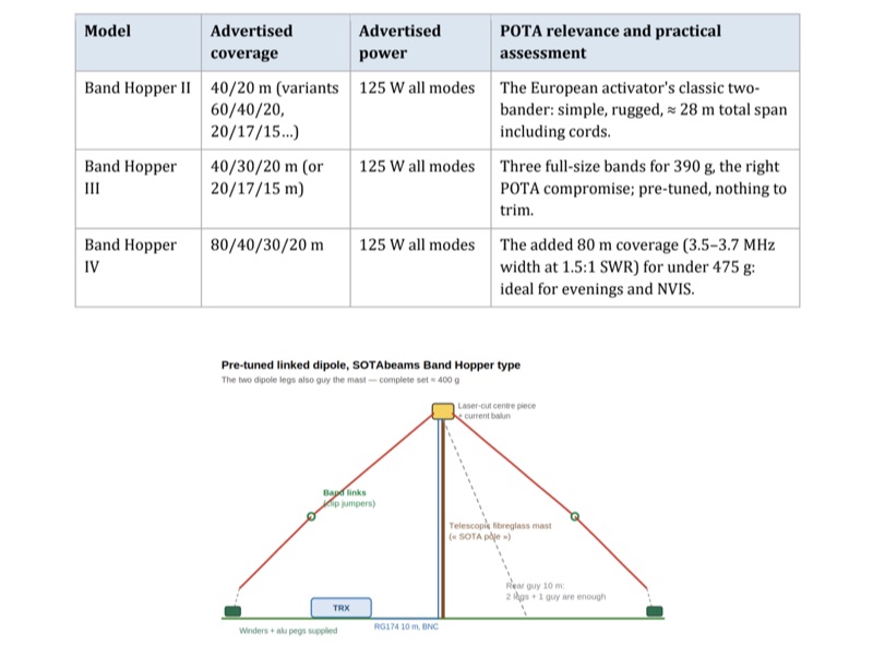 The resource discusses antenna families frequently utilized by _Parks On The Air_ (POTA) activators, focusing on the specific requirements for portable operations. It highlights the need for lightweight construction, rapid deployment, and sufficient efficiency to achieve the minimum **ten contacts** required for activation. The guide addresses adaptability to diverse field conditions, including the presence or absence of trees and varying ground surfaces. For each antenna type, the article provides a principle diagram, outlines its operational strengths, and details its inherent limitations. It also includes external links to practical field experiences, offering real-world context for each design. The POTA program, which involves setting up a complete station in a park, often within **thirty minutes**, underscores the antenna's critical role in successful activations.
 -
 WB5NHL describes setting up a 160-meter antenna on a small suburban lot, where standard options like Beverage antennas and 1/4 wavelength verticals require extensive space and ground systems. Instead, Guy Olinger's Folded Counterpoise (FCP) provides a solution. The FCP minimizes ground losses by using a folded wire design, allowing effective antenna placement in limited space. The FCP, fed with an isolation transformer, enabled WB5NHL's first 160-meter antenna installation, offering improved performance despite space constraints.
 -
 Chavdar Levkov, LZ1AQ, presents an experimental comparison of small wideband magnetic loops, building on his previous work on wideband active small magnetic loop antennas. His research focuses on increasing loop sensitivity by maximizing the short-circuit current, which is directly tied to the "loop factor" M = A/L, where A is the equivalent loop area and L is its inductance. Levkov's methodology involves reducing inductance and increasing area through parallel or coplanar crossed (CC) configurations, comparing these designs against a reference single quad loop of 1 m2 area. Experimental verification included testing three distinct loop types: a simple quad loop, two coplanar crossed (CC) loops, and eight parallel loops, all designed to have a total geometric area of 1 m2. Measurements were conducted at 1.8, 3.5, 7, and 10 MHz using a small transmitter 270 meters away, with a Perseus direct sampling receiver for precise signal level assessment. The results consistently showed that CC loops, particularly Loop 5 (two CC circular loops with 1.44 m2 total area), yielded significantly higher currents, up to 9.1 dB over the reference loop at 3.5 MHz, validating M as a reliable predictor of loop sensitivity. Numerical simulations using MMANA further corroborated the experimental findings, demonstrating an almost perfect correlation between the calculated M factor and the induced loop current for 15 different loop models. Levkov concludes that CC loops offer superior sensitivity for a given loop area, while parallel loops are advantageous for minimizing physical volume. Practical recommendations suggest using loops with an M factor greater than 0.5 uA/pT for quiet rural environments, and he provides a spreadsheet tool, WLoop_calc.xls, to aid in optimizing loop configurations for specific operational needs.
 -
 The Beverage on Ground (BOG) antenna offers ham radio operators a compact alternative to traditional Beverage antennas, requiring less space and fewer support structures. This implementation, optimized for 1.8-7 MHz bands, describes ideal parameters: lengths of 60-90 meters, height of 2-10 cm above ground, and specific load resistances based on configuration. The article details experimental methods for determining optimal load resistance and presents matching systems to convert BOG impedance to 50 ohms. While less effective than classic 200-300 meter Beverages, the BOG provides directional reception in limited space, though performance varies with ground conditions and weather changes.
 -
 Addresses the common challenge of constructing effective dual-band antennas for VHF/UHF operations, specifically detailing a J-pole design. It covers the theoretical underpinnings, including calculations for quarter-wavelength radiator and stub sections, accounting for velocity factor and design frequency. The resource provides practical construction guidance using readily available materials like TV twin lead and coaxial cable, culminating in an antenna with a total length of approximately 52 inches. Performance metrics are presented, showing a measured SWR of 1.7:1 or better across most of the 2-meter band and less than 2:1 across the 70-cm band. These SWR measurements, referenced to 50-ohm impedance, were taken at the transmitter end of the feed line. The article also touches upon the necessity of a balun for proper impedance matching between the balanced J-pole and unbalanced coaxial feed line, suggesting a split-core cylindrical ferrite for this purpose.
 -
 The resource details the construction of a 433 MHz LoRa APRS iGate and a tracker, both built around _TTGO T-Beam v1.1_ microcontroller boards. Each board integrates an OLED screen, WiFi, GPS, and an SMA antenna connector, powered by an 18650 3.7 V lithium-ion battery or microUSB. The iGate operates on 433.775 MHz, with its status verifiable on aprs.fi, demonstrating practical implementation of LoRa-based APRS solutions. The methodology involves programming the modules using Visual Studio Code with the PlatformIO plugin. This process loads the necessary firmware and a JSON configuration file, which includes the operator's callsign and WiFi credentials for the iGate. The guide emphasizes the ease of programming and provides specific steps for configuration. Initial testing of the iGate and tracker, including smart beaconing configuration, is documented. The low power output of approximately 200 mW from the LoRa board's transmitter is noted, with suggestions for range extension through improved antennas or RF amplification. The author, N4MI, plans to deploy a higher-gain 70cm antenna for the iGate.