Search results
Query: 100
Links: 448 | Categories: 13
Categories
- Radio Equipment > HF Amplifiers > Acom 1000
- Radio Equipment > VHF-UHF Mobile > ICOM IC-2100H
- Radio Equipment > HF Transceivers > Icom IC-7100
- Radio Equipment > HF Transceivers > Icom IC-9100
- Radio Equipment > Receivers > Icom IC-R7100
- Radio Equipment > Antenna Tuners > LDG Z-100
- Operating Modes > Satellites > QO-100
- Radio Equipment > HF Amplifiers > Yaesu FL-2100
- Radio Equipment > HF Transceivers > Yaesu FT-100
- Radio Equipment > HF Transceivers > Yaesu FT-1000MP
- Radio Equipment > Microphones > Yaesu MD-100
- Radio Equipment > Scanners > Radio Shack PRO-94
- Radio Equipment > HF Transceivers > Yaesu FT-891
-
 Eham review for FT-1000d version
 -
 Valcom Guelph specializes in the design and manufacturing of a full range of MF Beacon 100 KHz - 600 KHz, AM Broadcasting 540 - 1700 KHz, HF 1.8 - 30 MHz, VHF 30 - 300 MHz and UHF 300 - 1,200 MHz and SHF up to 6 GHz antennas based in Canada
 -
 100 W output RF amplifier for 10 meter band project by W4NFR
 -
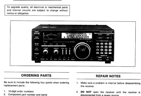 PDF File of the IC R7100 communication receiver service manual
 -
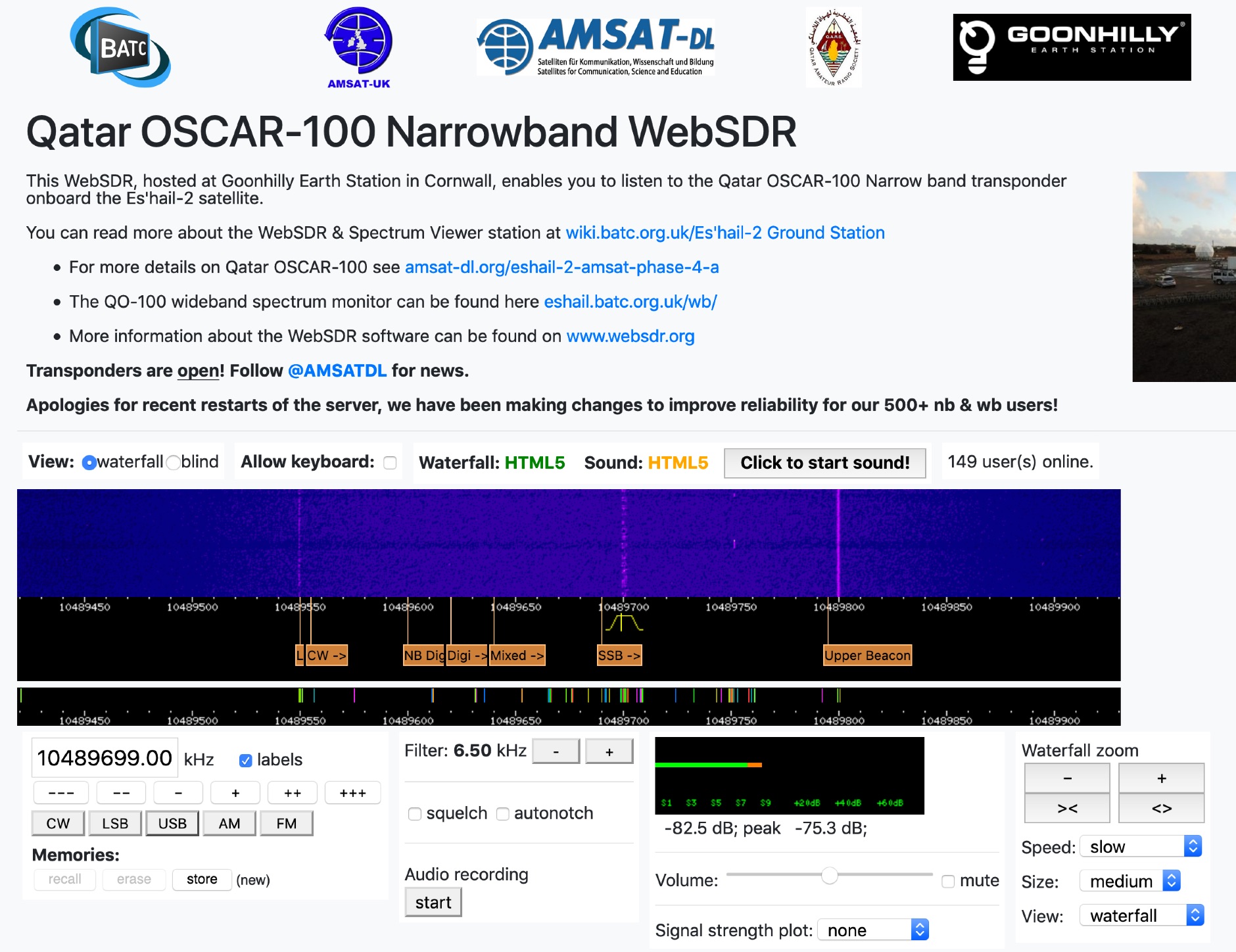 This WebSDR, hosted at Goonhilly Earth Station in Cornwall, enables you to listen to the Qatar OSCAR-100 Narrow band transponder onboard the Es'hail-2 satellite.
 -

-
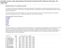 Comparison of FT-1000D FT-736R FT-817 FT-847 FT-897 IC-765 Orion TS-2000 Spectral purity of a continous carrier, of a SSB and CW signals
 -

-
 Experimenting vertical wire antennas for 40 and 20 meters supported by balloons resulting in excellent gain in RX and good overall performance against horizontal dipole
 -
 Meets 1st Wednesday monthly Sept. thru June. 100+ members, repeater W1WQM 145.150 / PL 127.3
 -
 Around 200 electronic circuits in pdf format or images, There are also over 1000 links to useful electronics, freeware, open source websites. There are some 100 useful documents, software and pcbs too. Mainly industrial electronics, instrumentation. Covers Various aspects of electronics and basics of circuit design.
 -
 All resources needed to the Yaesu FT 1000 MP & Mark V by VA3CR
 -
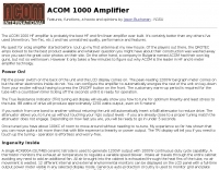 Features, functions, a howto and opinions by Jason Buchanan - N1SU
 -
 My personal page with a lot of INDIA FOX QSL Cards over 100.
 -
 Details the construction of an **HF converter** designed by M1GEO, George Smart, specifically to extend the frequency range of the FunCube Dongle Pro (FCD) for amateur radio reception. The FCD natively covers 64 to 1,700 MHz, but this project enables reception from 0 Hz to 64 MHz by up-converting signals to the FCD's operational range. It employs a **double-balanced mixer** with a 100 MHz local oscillator (LO) to translate incoming HF signals; for instance, a 1 MHz signal appears at 101 MHz within the FCD's passband. The design incorporates a 7th-order Chebyshev low-pass filter with a 62 MHz cutoff frequency at the input to mitigate image frequencies, ensuring cleaner spectral presentation. George provides the schematic, PCB masks, and Gerber files for replication, noting that Far Circuits also offers PCBs. The resource includes test results for the low-pass filter and measurements of LO leakage, identifying -36.8 dBm at 100 MHz as a potential sensitivity concern. M1GEO discusses potential improvements, such as adjusting the mixer's LO drive, adding a balance pot, or incorporating a post-mixer high-pass filter to reduce LO breakthrough. Audio recordings from 40m and 17m demonstrate the converter's performance with WRplus SDR software.
 -
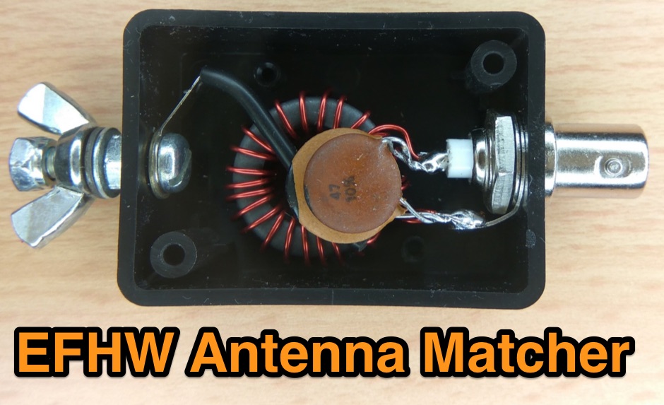 An end-fed-half-wave antenna matcher project based on a FT-82-43 core with a 100 pF and 45 pF capacitor in parallel
 -
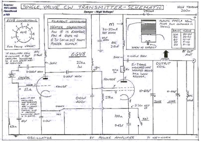 This transmitter was first constructed in 1987 and provided the author with his first real rig, capable of distances of more than about 100 metres.Use a 6GV8 tube.
 -
 Home Brew a 4-1000A RF power amplifier project by W4NFR
 -
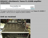 EB5AGV Workbench: Yaesu FL-2100B amplifier restoration
 -
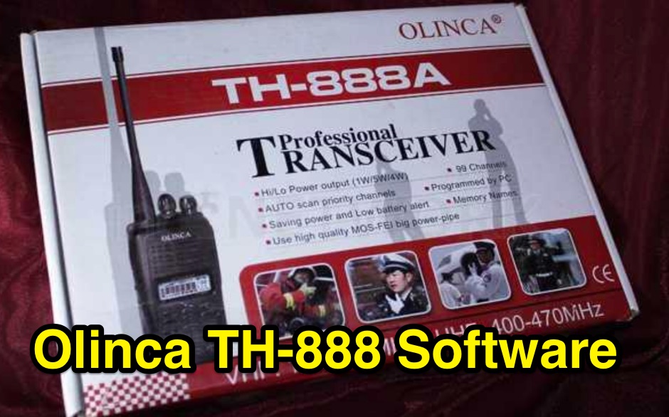 Free windows software to program or reset cara ht olinca th888a and th888S th888 th10 th2100 th2uv th9 handheld VHF UHF two way radios
 -
 Connecting the FT-1000MP to the Ten-Tec Centurion or Alpha 99
 -
 Southeast New Hampshire W1SRA / 147.000Mhz / Negative Offset / 100.0 PL Tone Welcome to the Sunday Night Net each Sunday evening at 8:00 PM.
 -
 Covers 10m 12m 15m 17m 20m 30m 40m and 100 KHz on 80m, & WARC Eham Reviews
 -
 Supplier and exporter of generator, diesel generator, petrol generator, industrial generator, silent generator, power generator, electricity generator, gas generator, air cooled generator, gensets 1kva, 2kva, 5kva, 10kva, 50kva, 100kva, 250kva
 -
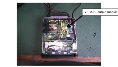 Replacing the Yaesu FT100D SRF7043 VHF/UHF RF MOSFET Power Amplifier
 -

-
 The _Sci.Electronics FAQ: Repair: RFI/EMI Info_ document, authored by Daniel 9V1ZV, provides a detailed analysis of computer-generated RFI/EMI, focusing on its impact on radio reception. It identifies common RFI sources such as CPU clock rates (e.g., 4.77 MHz to 80 MHz), video card oscillators (e.g., 14.316 MHz), and even keyboard microprocessors, all of which generate square-wave harmonics across HF and L-VHF regions. The resource outlines a systematic procedure for pinpointing RFI origins, including disconnecting peripherals and using a portable AM/SW receiver with a ferrite rod antenna to localize strong interference sources. The document categorizes RFI mitigation into shielding, filtering, and design problems, offering practical solutions for each. It recommends applying conductive sprays like _EMI-LAC_ or _EMV-LACK_ to plastic casings of radios, monitors, and CPUs to create effective Faraday cages, emphasizing proper grounding and avoiding short circuits. For filtering, the guide suggests using line filters, ferrite beads, and toroids on power and data lines, and small value capacitors (e.g., 0.01 uF for serial/parallel, 100 pF for video) to shunt RFI to ground. It also discusses the use of bandpass, high-pass, low-pass, and notch filters on the receiver front-end or antenna feed to combat specific in-band noise.
 -
 KB9AMG's Top WSPR Spots presents a focused online tool for monitoring **2-way WSPR reports**, specifically detailing propagation data from February 2026 through March 2026. This resource aggregates _WSPRnet_ data, allowing radio amateurs to observe weak signal propagation conditions across various bands. The interface is straightforward, presenting callsigns, frequencies, signal-to-noise ratios, and distances for each reported contact, which is crucial for understanding current band openings and signal paths. The utility of this WSPR spotter lies in its ability to quickly visualize global propagation. Users can identify active stations and assess signal viability over long distances, with reports often showing contacts spanning thousands of kilometers. For instance, a typical WSPR report might indicate a signal from Europe reaching North America with a _SNR_ of -25 dB, demonstrating effective low-power communication. This data is invaluable for planning DX operations or evaluating antenna performance under actual propagation conditions.
 -
 This site is dedicated to design and analysis of micro- and millimeter wave filters from 0.5 to above 100 GHz.
 -
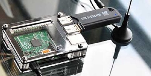 Build and run your own ADS-B receiver for 100 USD with a Raspberry Pi
 -
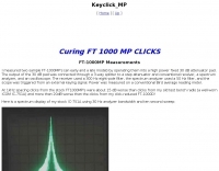 Modification to solve key clicks on FT 1000 MP
 -
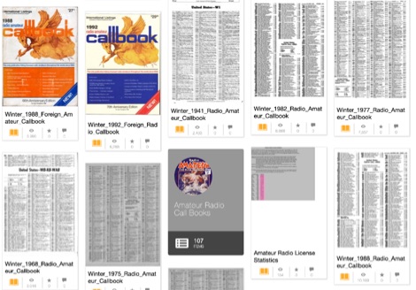 Indexes over 100 digitized amateur radio callbooks, primarily from the early to mid-20th century, providing a historical record of callsign assignments and licensee data. The collection facilitates research into past amateur radio operations, tracing callsign lineage, and identifying operators from specific eras. Each entry typically includes the callsign, licensee name, and geographic location as published in the original printed volumes. Users can browse the collection by publication date or utilize the search function to locate specific callsigns or names within the archived documents. The resource serves as a valuable repository for historical amateur radio data, supporting genealogical and operational research. Access to these scanned documents is provided directly through the Internet Archive platform, ensuring long-term preservation and availability of these historical amateur radio records.
 -
 The resource provides coaxial cable attenuation data, listing signal loss in dB per 100 feet for various cable types across a frequency range from 1 MHz to 5.8 GHz. The initial table details attenuation for cables such as _RG-58_, _RG-8X_, and RG-213, with impedance values of 50 ohm or 75 ohm, at frequencies up to 1 GHz. For example, _RG-58_ exhibits **0.4 dB** loss at 1 MHz and **21.5 dB** loss at 1 GHz per 100 feet. A subsequent table expands on this data, including LMR series cables like _LMR-400_ and LMR-600, along with other types such as 9913F7 and RG214. This section covers frequencies from 30 MHz to 1,500 MHz, also noting the outer diameter of each cable. For instance, _LMR-400_ (0.405" diameter) shows **0.7 dB** loss at 30 MHz and 5.1 dB loss at 1,500 MHz per 100 feet. The final section focuses on VHF/UHF/Microwave amateur and ISM bands, presenting attenuation in dB per 100 feet (and meters) for frequencies including 144 MHz, 450 MHz, and 2.4 GHz. This table includes larger diameter hardline options like 1/2" LDF and 7/8" LDF, in addition to flexible coaxial cables. For example, 1/2" LDF cable demonstrates **0.85 dB** loss at 144 MHz and 6.6 dB loss at 2.4 GHz per 100 feet. DXZone Focus: Coaxial cable attenuation | LMR-400 | RG-58 | 5.8 GHz
 -
 Demonstrates the _RoMac Automatic CW Identifier 2012_ software, a Windows application designed to automate station identification and provide a tuning pulser. It can send CW identification via a sound card's audio output or by keying a radio's manual CW jack using a serial port's DTR line. The software also supports CAT commands for various Kenwood, Yaesu, Flex, and Elecraft radios, enabling automatic mode and frequency changes for ID transmission. It integrates with USB audio-capable radios like the Icom 7300 and Yaesu FT-991, simplifying connectivity with a single USB cable. The application features a fully programmable interface, adjustable CW speed from **5 to 35 WPM**, and ID intervals from **5 to 30 minutes**. The integrated "Pulse Tuner" function allows for safe amplifier and antenna tuner adjustments by sending short audio tones or rapid CW keying, with an adjustable duty cycle from 1% to 100%. It offers compatibility with a wide range of transceivers and amplifiers, and a schematic for a basic sound card interface is included for users without existing setups.
 -
 The BTech DMR-6X2 dual-band DMR handheld radio is thoroughly reviewed, detailing its features and performance for amateur radio operators. This resource covers the radio's capabilities for both VHF and UHF frequencies, supporting Tier II DMR digital and FM analog modes. It highlights key specifications such as its **136-174 MHz** and **400-480 MHz** frequency ranges, CTCSS/DCS, DTMF, 2-TONE, and 5-TONE signaling, and its _digital simplex repeater_ function. The review provides a comprehensive unboxing experience, listing included accessories like two Li-Ion batteries (2100 and 3100 mAh), a programming cable, and a 37-page English user guide. It also specifies the radio's physical dimensions of 5.1 x 2.4 x 1.5 inches and weights of 9.9 oz with the 2100 mAh battery and 10.8 oz with the 3100 mAh battery, offering practical insights for hams considering this transceiver.
 -
 137 kHz propagation analysis details ground wave and sky wave mechanisms, drawing heavily from **CCIR Rec. 368-6** for ground wave field strength predictions and **CCIR Rep. 265-7** for sky wave modeling. The resource presents field strength values for 1 W ERP at varying distances, considering ground conductivity and permittivity for ground wave, and ionospheric height (70km daytime, 90km nighttime) for sky wave. Key factors like ionospheric focusing (factor "D"), reflection coefficient ("RC"), and antenna ground pattern factors ("Ft", "Fr") are quantified for 137 kHz, enabling calculation of sky wave field strength. Practical coverage ranges are derived for 137 kHz, showing useful ground wave coverage up to 1600 km over seawater and 1100 km over average ground, assuming a -9 dBuV/m noise floor. Sky wave coverage extends beyond 2200 km during night-time and winter daytime, but is negligible during summer daytime at solar minimum. The document also compares ground wave and sky wave strengths, identifying crossover distances at 550 km (night-time), 750 km (winter daytime), and 1250 km (summer daytime), where interference fading can occur. Adjustments for solar maximum conditions are provided, indicating 2-11 dB higher sky wave values depending on distance and season.
 -
 The IFR-100 PMR446 radio, developed by ICIT Co., Ltd., incorporates a unique _private speaker_ function. This feature enables users to receive communications discreetly, preventing audio from being broadcast aloud from the radio's internal speaker. Instead, the operator can hear transmissions exclusively through a connected earpiece or similar accessory, facilitating private talk mode operations. ICIT Co., Ltd. positions itself as a primary developer and manufacturer of PMR446 equipment within Korea. Their product line emphasizes innovative features designed to enhance user privacy and operational flexibility in short-range, license-free radio communications. The company's focus is on delivering specialized two-way radio solutions. The resource highlights the company's manufacturing capabilities and its commitment to developing distinct functionalities for the PMR446 market. It underscores their role in providing specific communication tools for users requiring secure and private audio reception.
 -
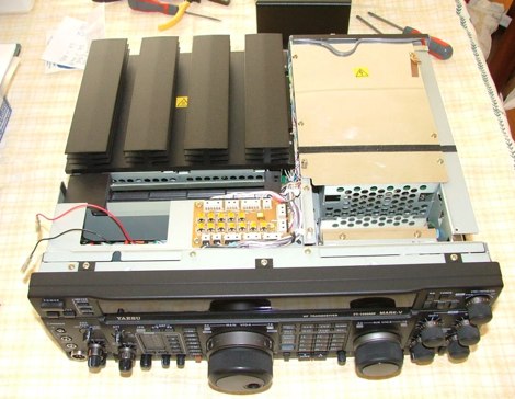 Keyclicks and NB modifications for the Yaesu FT-1000MP Mark-V HF transceiver
 -
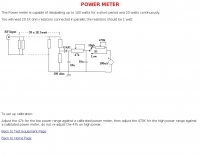 This Power meter is capable of dissipating up to 100 watts for a short period and 20 watts continuously
 -
 Fixing notice subtle distortion on SSB receive audio on the Yaesu FT-1000D
 -
 Solar activity can aid or hamper HF propagation beyond line-of-sight range, WA1SVF and N6BV answers to questions about Sun influence on radio signals propagation
 -
 A synthesized 2.3 GHz Amateur Television (ATV) transmitter design, conceived by Ian G6TVJ, is presented, targeting broadcast-quality video performance on the 13cm band and extending up to 2.6 GHz. The core of the design utilizes a commercial Z-comm Voltage Controlled Oscillator (VCO) that tunes from 2.2-2.7 GHz, providing a +10 dBm output and simplifying RF alignment. This VCO's stability, originally intended for narrowband applications, readily accepts high-frequency video modulation, contributing to the transmitter's robust performance. The exciter stage, incorporating a Mini Circuits VNA 25 MMIC amplifier, boosts the signal to +16dBm, while a Plessey SP4982 prescaler divides the output frequency for the synthesizer. The synthesizer employs a Motorola MC145151 CMOS parallel IC, favored over the common Plessey SP5060 for its superior video modulation characteristics and ease of programming without microprocessors. This choice addresses issues like LF tilt and distorted field syncs often seen with SP5060 designs, particularly when operating through repeaters or over long distances. The MC145151 divides the signal further, enabling precise frequency stepping, with programming handled by EPROMs for channel selection and LED display. The loop filter network, critical for video integrity, was developed through experimentation to prevent the PLL from reacting to video modulation, ensuring a clean transmitted picture. The transmitter incorporates a Down East Microwave commercial power amplifier module, delivering approximately 1.6W output, driven by the exciter through a 3dB attenuator. Construction involves surface-mount SHF components on micro-strip lines etched onto double-sided fiberglass board, housed within a tinplate box. The design boasts no AC coupling in the video path, preserving low-frequency response, a common failing in other ATV transmitters. Performance tests with a 50Hz square wave revealed no LF distortion, and a calibrated "Pulse & Bar" signal showed a near 100% HF response, demonstrating its capability for high-quality ATV transmissions.
 -
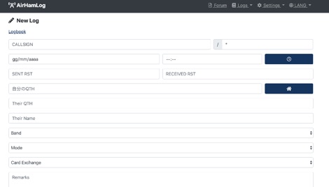 Facilitates logging of amateur radio contacts directly within a web browser, enabling seamless operation across various devices including Windows, macOS, Linux, iOS, and Android. This web-based application stores all log data securely in the cloud, providing accessibility from any internet-connected location. It supports importing existing log data via CSV files, with future plans for _ADIF_ file import, and offers a robust QSL card generation feature, producing print-ready PDF files in standard 148mm x 100mm dimensions. The platform integrates with Japanese government databases to automatically populate callsign-related information such as station location and license issue dates, streamlining data entry. It also assists with JCC/JCG searches for accurate QTH logging. The service leverages SSL encryption for all communications and benefits from security oversight by certified information security professionals. Users can register using email/password or existing Facebook/Google accounts, and the beta version is currently available for free. The system has processed over **5,297,881** logs, with **28,369** logs recorded in the past 24 hours.
 -
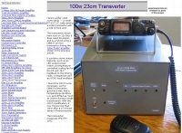 A small (FT-817) I.F. radio driving a 100w transverter with a 1db nf front end.
 -
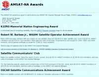 Make 1000 two-way contacts with any station on any satellite
 -
 Article about an end-fed anntenna for the 17 and 12 WARC Bands. 30 meters is not included in this project. This antenna includes a 14 windings unun impedance transformer using a FT-140-43 ferrite toroid, that should be enought for a 100W PEP.
 -
 Freeband modification for the Yaesu FT-100
 -
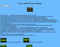 A nice review of the Acom 1000 HF and 6 meter RFpower amplifier by Acom in Dutch and with online google translation available. Includes pictures and notes of the popular amplifier by Acom.
 -
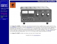 Technical specifications and details of the Yaesu FL-2100B HF Power Amplifier
 -
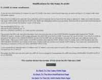 Adding a full power output 12 meter band capability to the Yaesu FL-2100 despite of 10 meter.