Search results
Query: 40 meter band
Links: 286 | Categories: 5
-
 The antenna in this project is a modification of the techniques used to design a multiband fan type dipole with little or no tuning involved having a total space of 105 feet
 -

-

-
 A monoband delta loop antenna for the 7 MHz. This vertically polarized DX Antenna is a full wavelength sngle side antenna and has a total length of 42.3 meters (137,1 inch) Can be easily setup with a flag pole or fishing pole as center top mast. For optimal performance lower side should be at 2 meter above the ground. This antenna offers a low radiation angle and 1 DB Gain.
 -
 Complete collection of the four main parts of this excellet research on modelling and designing half wave dipole antennas for 40 meters band, covering all aspects beginning from full wave length antennas, to shortened, loaded and reshaped dipoles
 -
 A dual band dipole antenna for 40 and 80 meters band. Total lenght of 26 meters, foreseen two coils at aprox 11 meters distance from center feed.
 -
 Fifty-three digital modes, including PSK31, RTTY, and JT65, are explored in this resource, providing detailed descriptions of their underlying technologies and typical use cases. It covers error correction methods like ARQ in PACTOR and FEC in JT65, alongside modulation schemes such as FSK and PSK. The content highlights the evolution of digital communication from traditional TNC-based systems to modern sound card implementations, emphasizing the role of personal computers in advancing these modes. Specific modes like AMTOR, PACTOR, and G-TOR are discussed, noting their baud rates and error correction capabilities. For instance, AMTOR operates at 100 baud, while PACTOR offers 200 baud with Huffman compression. The article also delves into newer modes like MFSK16, which uses 16 tones and continuous Forward Error Correction, and Olivia, capable of decoding signals 10-14 dB below the noise floor. Each mode's bandwidth, speed, and resilience to propagation challenges are examined, such as MT63's 1 KHz bandwidth and 100 WPM rate, or Hellschreiber's 75 Hz bandwidth and 35 WPM text rate. The resource also lists predominant USA HF digital frequencies for bands like 160, 80, and 40 meters, specifying segments for PSK31, RTTY, SSTV, and Packet. It includes links to freeware and shareware sound card software such as Digipan, FLDigi, and MixW, enabling amateurs to experiment with these modes.
 -
 A multiband Fan Dipole that works on 40 20 15 meters band, making a folded dipole for 7 MHz band and additional element for the 21 MHz and 14 MHz
 -
 Full article on how to build a home-made wire dipole antenna for 40 and 80 meters band. Article is fully in italian, as it was published on ARI RadioRivista, but is plenty of self explaining pictures that will guide you on homebrewing this trapped dipole antenna for the lower amateur radio bands.
 -
 This article is about a home made project of a whip antenna for 2 meters band. Includes lenght of whip for all frequencies from 140 MHz to 151 MHz both in mm and inches
 -
 An antenna for 80 meters band for those who does not have enough space to setup a halwave wire dipole that is aprox 130ft or 40 meters. The antenna is an open-wire-fed shortened dipole
 -
 An inverted V Dipole antenna for HF bands, working on 10 20 40 and 80 meters band. PDF Presentation
 -
 Presents field test results for an **elevated SuperAntenna MP-1** portable antenna, configured on a tripod for HF operations. The resource details the antenna's setup and performance during a portable activation, focusing on its use across the 40-meter, 20-meter, and 17-meter amateur bands. It includes observations on signal reports and operational considerations for this specific portable antenna configuration. The content provides practical insights into deploying the MP-1 antenna in a non-ground-mounted setup, which is often a point of interest for portable and QRP operators. It documents the author's experience with the antenna's tuning and effectiveness for making contacts under real-world conditions, offering a user-perspective review of its capabilities. The article also features photographic evidence of the antenna's deployment, illustrating the tripod mounting and the overall portable station setup.
 -
 The 2200-meter band (135.7-137.8 kHz) presents unique challenges for amateur radio operators due to its narrow 2.1 kHz bandwidth, low signal levels, and high noise. W1TAG explores various transmission modes suited for this demanding environment, highlighting that traditional voice modes like SSB and AM are impractical. Plain old CW serves as the baseline, demonstrating effectiveness across different modes, though signal-to-noise ratio (SNR) significantly limits practical speeds. The article notes that reducing CW speed below 5 WPM can improve copy, especially with computer-aided spectrum analysis software capable of decoding signals too weak for human ear reception. QRSS, or "CW sent slowly enough that speeds are best expressed in seconds per dot," is a key mode for LF work, with examples ranging from 3 seconds/dot to extreme 240 seconds/dot transmissions. _Argo_ by I2PHD is mentioned as a simple program for QRSS, enabling reception of signals like BRO, a Part 15 beacon, at a distance of **1100 miles**. Other modes discussed include Dual Frequency CW (DFCW), which uses frequency shifts to distinguish dots and dashes, and Binary Phase Shift Keying (BPSK), a phase modulation technique employing 0 to 180-degree phase flips. WOLF (Weak-signal Operation on Low Frequency), a specialized BPSK form by KK7KA, encodes 15-character messages into 960-bit packages, taking 96 seconds to transmit, and has demonstrated successful reception over **672 seconds** for a message from a 1-watt beacon. Further modes include PSK, FSK variations like JASON and MSK, and graphical modes such as Hellschreiber and Chirped Hell. The article concludes with a practical chart comparing the time required to send a simple message like "WD2XES FN42CH " across these diverse LF modes, offering valuable insights for operators planning contacts on the low bands.
 -
 Roach pole vertical antenna for 40 and 30 meters band featuring good performance on short skips contacts compared to wire dipole
 -
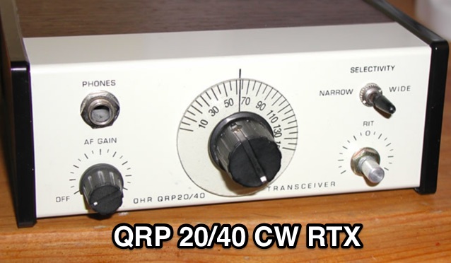 QRP CW transceiver Kit for 20 or 40 meter band, by OKA Hills Research, assembly history and description
 -
 This simple antenna was installed on the attic. Antenna was matched with help an Automatic ATU in 40, 30, 20, 17, 15, 12 and 10 meter amateur Bands. The Antenna worked satisfactory on the above mentioned bands.
 -
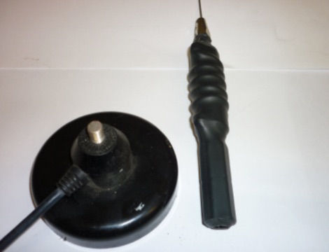
 A home made portable vertical antenna, that with a single 1/4 wave counterpoise wire is possible to achieve less than 1.5:1 SWR on 40, 30, and 20 meter bands. It is basically a center load, shortened ground plain vertical antenna.
 -
 A loop antenna for 80 and 40 meters band, the main loop is based by a crossed line using aluminium strip lines. The main loop diameter is 150 cm.
 -
 This antenna is an off-center fed spiral dipole for 40 meters. The spiral dipole is very compact, making it well-suited for limited space (like an apartment patio), while the off-center feed gives the antenna some multiband capability.
 -
 A simple portable dipole antenna for the 40 meter band using a total lenght of 18 meter. It can be used for 80 to 10 meters coverage using a antenna tuner.
 -
 The Boone Area Radio Klub (BARK) serves Boone County, Iowa, as its local amateur radio club, actively welcoming visitors to its meetings and weekly ARES nets. The club maintains a 2-meter repeater on 146.850/250 MHz with a 114.8 Hz tone and a 440 MHz repeater on 443.9+ MHz, both situated at the Boone County Hospital, with a simplex fallback on 146.550 MHz for the 2-meter net. Additionally, BARK supports the Iowa 160-meter ARES net at 1.972.5 MHz, which operates at 9:30 PM on Sundays, featuring a rotating schedule of net controls including KNØR, KBØMPL, NØISU, KEØQEU, and KBØLPI. BARK conducts bimonthly license testing sessions on the second Saturday of even-numbered months, with specific dates like October 19, 2024, at the Hamboree, requiring a $15 fee and prior FCC Registration Number (FRN) acquisition. The club's activities are well-documented through numerous photo galleries from past Field Days (1998, 1999, 2008, 2010, 2013, 2017, 2018, 2019), JOTA events (2013), and special event stations (2010 B&SVRR&M). Members like KBØMPL (Margot Conard) have contributed educational PowerPoint presentations on topics such as "Fun with Handie Talkies," "HF Propagation," and "Digital Mode - FLDIGI - OLIVIA 8/500 - JT65 HF - BAND PLANS." The club's officers, as of May 2018, include WØFS (Clay Conard) as President, NØISU (Mitch Carroll) as Vice-President, and KBØLPI (Eric Sloan) as Treasurer/Secretary, guiding the club's operations and community engagement.
 -
 A portable home made wire dipole antenna that works on 40 30 and 17 meters band.
 -
 The ZS1J/B beacon operates on 28.2025 MHz with 5 Watts output to a half-wave, end-fed vertical antenna, initially installed in 1977 as ZS5VHF near Durban. The 10-meter transmitter is a modified 23-channel CB radio, and the identification keyer uses a diode matrix unit with TTL ICs from the same era. After relocation to Plettenberg Bay in 1993, the beacon has been in continuous service, with additional QRP transmitters later installed for other bands. In 1994, a single-transistor, 80-meter, 0.5-watt QRP transmitter with a half-wave dipole was added on 3586 kHz, followed by a 160-meter, 0.5-watt unit on 1817 kHz. A 30-meter, 0.5-watt transmitter was installed in 1996, operating on 10.124 MHz. In 2002, a 40-meter QRRP beacon on 7029 kHz, with an output of 100 microwatts, achieved DX reports up to 1100 km from ZS6UT in Pretoria. Best DX reports for the 80m and 160m beacons came from 9J2BO.
 -
 Low-frequency (LF) radio time signals, operating primarily in the 40–80 kHz range, are broadcast by national physics laboratories for precise clock synchronization. Transmitters like **JJY** (40 kHz, 50 kW; 60 kHz, 50 kW), RTZ (50 kHz, 10 kW ERP), MSF (60 kHz, 15 kW ERP), WWVB (60 kHz, 50 kW ERP), RBU (66.66 kHz, 10 kW), and DCF77 (77.5 kHz, 50 kW) cover vast geographic areas, often several hundred to thousands of kilometers. LF signals offer distinct propagation advantages over higher-band transmissions such as GPS. Their long wavelengths (3–6 km) enable effective diffraction around obstacles like mountains and buildings. The ionosphere and ground act as a waveguide, eliminating the need for line-of-sight and allowing a single powerful station to cover extensive regions. Ground wave propagation minimizes ionospheric variability effects on transmission delay, and signals penetrate most building walls effectively. Robust and low-cost receivers, often priced at 20–30 USD/EUR, are widely used in radio clocks. These receivers typically comprise a tuned ferrite core antenna, a receiver IC (e.g., Atmel T4227, U4223B, MAS1016) for amplification and AM detection, and a microcontroller for decoding the time signal and phase-locking a local clock. Specific components for DCF77, MSF, and WWVB are readily available from vendors like HKW Elektronik and Ultralink.
 -
 The PG7V Contest Calendar provides a curated listing of significant **HF contests**, with a particular focus on events relevant to European amateur radio operators. It details contest specifics such as start and end times in UTC, eligible bands (e.g., 80 meters, 40 meters, 10 meters), and required exchange information (e.g., serial number, CQ-zone, DOK, locator, age). The calendar includes diverse modes like CW, SSB, PSK63, RTTY, and FT4, catering to various operating preferences. Featured contests include the RSGB 80m Club Championship, WW WPX Contest, IARU Region 1 Fieldday, and ARRL International Digital Contest. Each entry links directly to the official contest rules for detailed information. The calendar also notes specific participation rules, such as the 1 KHz QSY requirement in the HA3NS Memorial Contest or the 24-hour single-operator time limit in the ARRL International Digital Contest. This resource is updated regularly, ensuring timely information for upcoming **contest operations** over a four-week period. It serves as a practical tool for hams planning their contest activity.
 -
 A portable operation experience with a SpiderBeam pole during a contest, testing wire antennas, like dipole and delta loops configurations on 20 40 and 80 meters band.
 -
 The Buddistick antenna, as demonstrated by KP4MD, effectively handles up to **250 watts** and provides coverage from 40 through 10 meters, with an optional coil extending operation to 80 and 60 meters. KP4MD's video presentation meticulously describes the antenna setup, emphasizing the critical role of the _shunting coil_ for achieving resonance on lower bands like 40 and 80 meters. This practical approach highlights how a compact antenna can deliver solid performance from a constrained location. SWR curve diagrams are included, clearly illustrating the impact of the shunting coil on the antenna's resonating frequency. These visual aids provide concrete evidence of the adjustments needed for optimal operation across different bands, particularly when space is at a premium. KP4MD's insights are particularly valuable for hams operating from apartments or other limited spaces, showcasing real-world results from a balcony installation.
 -
 IARU HF Contest, goal is to contact as many other amateurs, especially IARU member society HQ stations, around the world as possible using the 160, 80, 40, 20, 15 and 10 meter bands.
 -
 An interesting article on end fed half-wave wire antennas with a couple of original experiments. Author illustrate the role of the QRP matchbox, and a 40/20 meter antenna with a center stub making it a large bandwidth antenna for 40 and 20. Includes also an 80/40 end fed with the typical coil to make it available on 80 merts band.
 -
 Basic magnetic loop antenna examples and loop aerials theory explained. This article inclued some interesting tricks on building magnetic loop antennas and an usefull excell sheet to help compute magneti loop antennas calculating power efficiency from 10 to 40 meters band
 -
 This page describes a comparison study on seven different beam antennas for 40 meters band. Yagi antennas, moxon antennas, mini horse all antennas are described with schema diagram , azimuth plot and SWR F/B Gain diagram
 -
 Basically, this antenna is a 23-foot wire fed through a 4:1 un-un transformer. This antenna can be easily used in portable operation, for operating all bands from 40-10 meters.
 -
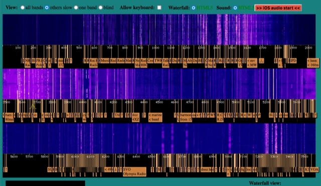 WebSDR receiver located near Krizevci, Croatia with 0-2 MHz, 60-80 meters band and 40-49 meters band
 -
 This page describes an entirely simple, One-Knob matchbox that will match this antenna efficiently on 40, 30 and 20m, using a simple circuit that can be switched between series-resonant and parallel-resonant with just one banana jumper
 -
 The ARRL's End-Fed Half-Wave (EFHW) Antenna Kit is an easy-to-build four-band antenna designed for 10, 15, 20, and 40 meters. Ideal for portable operations, it includes a 49:1 impedance transformer for compatibility with most transceivers. This project, detailed with step-by-step assembly instructions, involves creating a weatherproof enclosure and impedance matching network. The kit simplifies HF operations and supports multiple configurations, making it a versatile tool for amateur radio opertors.
 -
 256 memories enable the _AT-AUTO_ to recall settings across multiple bands, making it efficient for operators who frequently change frequencies. The tuner is compatible with various antennas and amplifiers, such as the Mercury LUX, and integrates seamlessly with radios like the FLEX 6400 using an RS232-USB connection. This integration allows the tuner to follow frequency changes without additional input, enhancing operational efficiency. Despite being out of production, the _AT-AUTO_ remains supported by Kessler Engineering, which offers firmware updates and repair services. The tuner features a cross-needle SWR meter, providing quick visual feedback during tuning. It also includes a QRO keyline circuit to protect amplifiers during tuning. Users appreciate the tuner's ability to track radios via CAT control, avoiding automatic tuning during QSOs, a common issue with other models. The _AT-AUTO_ is praised for its durability and performance, with many users noting its reliability over years of use. Its ability to handle legal limit power and its balanced line output make it a versatile choice for serious operators. Although it lacks some features like multiple coax outputs found in other models, its robust build and continued support make it a valuable tool for HF enthusiasts.
 -
 This type of antenna is a popular antenna design as the performance is very good across the HF bands and requires little or no tuning. It’s a dipole fed off center with a 4:1 balun at the offset feed point. The antenna shown covers 80, 40, 20 and 10 meters. The formula can also be used to adjust the overall length to cover more or fewer bands and the resulting overall length. 160-10m, 80-10m or 40-10 meters depending on your available space. Other bands will require a tuner.
 -
 Constructing a dual-band antenna for 40 and 20 meters often involves compromises in size or complexity. This resource presents a compact _open sleeve dipole_ design that addresses these challenges by using 450-ohm ladder line and folded elements to achieve a total length of approximately **17.17 meters**, significantly shorter than a full-size 40-meter dipole. The design leverages electromagnetic coupling, where a primary radiator handles the 40-meter band, and a second conductor resonates on 20 meters without direct electrical connection. This configuration eliminates the need for traditional traps, loading coils, or switching components, simplifying construction and reducing potential loss points. The antenna is fed with RG-58C/U coaxial cable, and a common-mode choke is recommended at the feed point to suppress sheath currents, ensuring a cleaner radiation pattern and minimizing RF in the shack. The design is well-suited for portable operations, field deployments, temporary installations, and restricted urban environments where space is a premium, offering solid performance on both HF bands.
 -
 A 3 band dipole antenna for 40-80-160 meter bands, It's made with easily available materials and is designed for inverted V mounting. The antenna is shortened for these bands, but still manages to make contacts in 80m and 160m with stations in Canada and the USA. The construction details are provided, including the dimensions of the antenna elements and the traps. The antenna is easy to build and provides good performance in all three bands. In Italian.
 -
 A dedicaed vertical antenna for 80 meters band based on a 40 meter vertical experiment
 -
 A 60-foot available space, for example, might necessitate a shortened multiband dipole array to cover 80, 40, and 15 meters effectively. This resource details the construction of such an antenna, combining full-size and coil-loaded dipoles on a single feedline. It addresses the common challenge of fitting multiple HF bands into restricted physical footprints, providing practical guidance for hams with smaller backyards or portable operations. The core of the offering is an interactive calculator that determines required loading coil inductance and dipole lengths for various amateur bands from 160m to 10m. Users input their available space, and the tool provides dimensions, coil turns, and an efficiency rating (Good or Fair) based on the antenna's electrical length relative to a quarter-wavelength. It also suggests suitable _PVC_ pipe diameters for coil forms. The article further illustrates a center feed-point assembly using an 18-inch section of 2-inch _PVC_ pipe, detailing eye-bolt spacing and coaxial connector installation. It emphasizes the importance of adequate spacing between parallel dipoles and offers customization options for the feed-point, including the addition of a _Balun_ for improved feedline isolation.
 -
 Experimenting with capacitive antennas for 40 and 80 meters band. A very space-saving antenna with good receivings caracteristics
 -
 With this antenna the coverage is 80,40,20,15 and 10 meter band without any antenna tuner and the average SWR is below 1.2 on phone bands. The total antenna lenght is about 23 meters , with one 20.4 meters long segment from the 1:49 transformer to the 110uh coil and about 2.2 meters long segment from the coil to the insulator.
 -
 Vertical end fed antenna used for portable operations. The antenna will work on 80 with acceptable results, it will work fine on 40m, and it will be a good deal better than a normal 1/4 wave GP on 20, 17, 15 meters.
 -
 WebSDR Pardinho SP Brazil providing access to HF bands 160 80 40 20 15 11 meters bands.
 -
 Operating in antenna-restricted communities presents unique challenges for amateur radio operators, often necessitating creative solutions for antenna deployment. This resource details the design and implementation of stealth antennas within a townhouse community in Exton, PA, where external antennas were strictly forbidden by covenants. The author, WB5NHL, describes his setup, which involved locating the shack in the basement and utilizing an unused space under the roofline of a finished third-floor loft for antenna placement. The content specifically addresses the practicalities of routing coax cables three floors and maximizing antenna performance within limited attic space. It covers solutions for multi-band operation, including dedicated sections for 40-10 meter and 80-meter antennas, along with strategies for mitigating potential interference issues. The approach emphasizes full compliance with community covenants, achieving maximum height-above-ground for horizontal antennas, enabling instant band switching, and efficiently utilizing available attic volume. While acknowledging limitations such as potential interference with high power and fixed antenna patterns, the resource provides a detailed account of a functional compromise for restricted environments. Links to individual pages on _coax cables_, _40-10 meter antennas_, _80-meter antennas_, and _interference issues_ offer deeper dives into each specific aspect of the installation.
 -
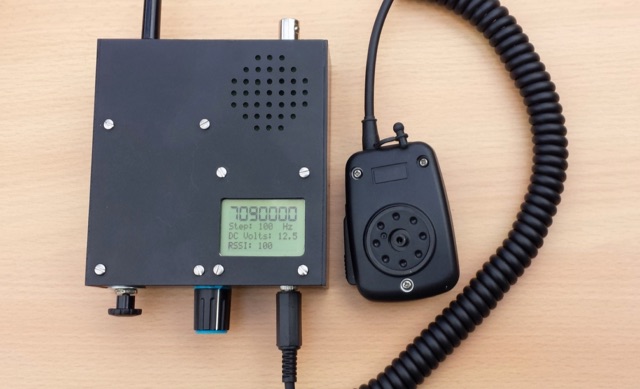 A home made portable QRP transceiver designed to work on 40 or 80 meters SSB band.
 -
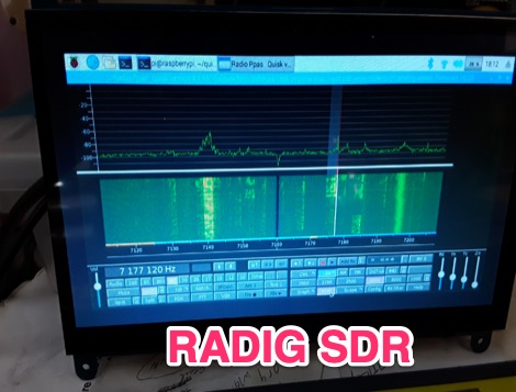 A new SDR radio concept developed by N6QW as an experimental 5W SDR transceiver for the 40 meter bands. Radio and Rig (RADIG) is a term conied by the author.
 -
 The longest element has a total length of 14m and has a boom length of 5.5 meters featuring a total bandwith of 166 kHz