Search results
Query: ground antenna
Links: 248 | Categories: 5
-
 This document details the construction of a multi-band end-fed antenna, suitable for situations with limited space for larger antennas. The design utilizes a 1:49 to 1:60 impedance transformer to match a half-wave wire antenna fed at one end. Compared to a traditional dipole, this antenna resembles a highly unbalanced Windom antenna with one very long leg and a virtual short leg. The design eliminates the need for radials but relies on the coax cable shield for grounding. The document recommends using at least 10 meters of coax and installing a common mode filter at the entry point to the shack for improved performance.
 -
 Steve Nichols, G0KYA, presents a practical examination of ground systems for vertical antennas, drawing heavily on the empirical research of Rudy Severns, N6LF. He explains that a robust radial field is crucial for ground-dependent verticals, effectively replacing the antenna's "missing half" and mitigating severe RF absorption in lossy soil. Nichols clarifies that surface radials do not strictly require a quarter-wavelength; instead, deploying a minimum of 16 to 32 shorter wires often yields superior results compared to fewer, longer ones. The presentation also addresses the common SWR paradox: a poor ground might show a perfect 1:1 match, but adding radials, while potentially raising the SWR to around 1.4:1, significantly improves true radiation efficiency. Nichols defines counterpoises as elevated wire networks that substitute for earth connections, offering solutions for limited-space installations, such as the **Folded Counterpoise (FCP)** for 160 meters. This resource provides actionable engineering data for optimizing vertical antenna performance.
 -
 This article presents the C-Pole antenna project, a compact, ground-independent vertical antenna designed for amateur radio operators. It features a folded half-wave dipole configuration that eliminates the need for radials, making it suitable for various locations, especially in deed-restricted areas. The C-Pole offers efficient performance with a 2:1 SWR bandwidth of approximately 3%, and it can be easily constructed using common materials. Additionally, the article discusses practical aspects such as feed-point impedance transformation and balun design to optimize functionality and minimize losses.
 -
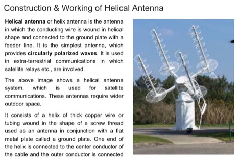 Helical antenna or helix antenna is the antenna in which the conducting wire is wound in helical shape and connected to the ground plate with a feeder line. It is the simplest antenna, which provides circularly polarized waves.
 -
 Operating from Banana Island, Sierra Leone (AF-037), the 9L2019 DXpedition by F6KOP and a ten-operator team used the callsign 9LY1JM from January 9-21, 2019. This detailed report covers the logistical challenges, including securing visas and licenses with local assistance from Mark 9L1YXJ and Gregory of Dalton’s Guest House. The team deployed monoband quarter-wave verticals on the beach and two Beverage on Ground (BOG) antennas for Europe/Asia and the USA, operating four stations simultaneously. Technical hurdles encountered included high tides submerging antennas, requiring repositioning, and persistent QRM between closely spaced stations, mitigated by doubling filters. CW signal irregularities at 30-32 WPM were resolved by PC and WINTEST restarts. A significant FT8 logging bug was identified and corrected with on-site software. Despite these issues, the team logged over 4,000 QSOs in the first 24 hours, averaging 5,000 QSOs daily, with a peak of over 6,000 in one day. Propagation varied, with excellent 160m conditions on January 12 yielding over 750 QSOs, and a later four-hour opening pushing the 160m total past 1,600. High bands were challenging due to low solar activity, but mid-bands provided intense pileups and rapid continent-wide contacts. The DXpedition concluded with nearly 50,000 QSOs, including a successful school QSO with Collège Doisneau de Sarralbe (57), managed by F1ULQ and F6KFT.
 -
 Ground Station offers real-time satellite tracking and radio communication capabilities, primarily for amateur radio operators engaged in satellite operations. It utilizes **TLE data** from sources like CelesTrak and SatNOGS for precise orbital prediction and integrates with various SDR devices, including RTL-SDR, SoapySDR, and UHD/USRP radios, to receive live signals. The software provides automated antenna rotator control and **Hamlib-compatible** rig control with Doppler correction, crucial for maintaining signal lock on fast-moving LEO satellites. It supports IQ recording in SigMF format and decodes several digital modes such as SSTV, FSK, GFSK, GMSK, and BPSK with AX25 USP Geoscan framing. Dedicated interfaces are available for satellite tracking, SDR waterfall displays with live transcription and packet decoding, and telemetry packet viewing. Users can manage TLE data synchronization and SDR hardware, along with browsing decoded outputs through an integrated file browser. An observations dashboard and DSP topology view further enhance the operational experience, providing comprehensive tools for monitoring and analyzing satellite passes.
 -
 This project details the construction of a compact, circularly polarized Quadrifilar Helix Antenna (QHA) designed for 146 MHz operation. The antenna features a 1/2λ1/2λ helical design with a 2.6:1 aspect ratio, providing 4.5 dB gain and a spheroid radiation pattern. It is ground plane independent and compatible with both vertical and horizontal polarizations, making it ideal for terrestrial and space communications. The design includes step-by-step instructions for building the antenna using readily available materials like aluminum rods, PVC pipes, and RG-58 coaxial cable. The antenna's performance has been validated through comparisons with commercial omnidirectional antennas, showing superior results.
 -
 A homemade quarter wave ground plane anntenna for 4 meters band.
 -
 The quarter-wave Marconi working against ground is a popular and inexpensive antenna for 160 meters. A lot of newcomers to the band favor this simple antenna because it's easy to put up, it isn't too big, and it works.
 -
 This project outlines the construction of a simple TEFV (Tilted End-Fed Vertical) antenna suitable for backyard or park installations. The design requires basic materials such as 100 feet of coated stranded copper wire, wood stakes, metal ground rods, a non-conductive fiberglass pole, and essential tools like wire cutters and a soldering iron. The antenna is supported by a 20-33 feet tall pole and includes a 9:1 unun for impedance matching and a resistor for tuning. Step-by-step instructions guide the assembly, from preparing the wire and pole to connecting the unun and resistor, ensuring a functional and durable setup for outdoor use.
 -
 Experimenting and testing vertical antenna for HF bands on mobile operations.
 -
 A 5/8 λ antenna, often thought to be ideal for all frequencies, has unique characteristics that don't universally apply. First introduced for medium-wave radio, it works optimally at 225° antenna length over ideal ground, yielding high efficiency. However, at VHF and higher frequencies, it offers no advantage over other antennas due to real ground conditions and complex matching requirements. DIY calculators provide only rough estimates, useful as a starting point for simulations, not for precise builds.
 -
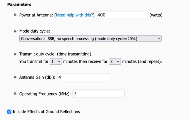 To use the RF Exposure Calculator, fill-in the form with your operating power, antenna gain, and the operating frequency. Depending on how far above ground the RF source is located, you might want to consider ground reflections too.
 -
 The author shares a unique experiment with a 200ft Grasswire antenna—laying wire directly on the ground. Despite inherent losses, the setup enables successful radio communication with a Kentucky station, highlighting the antenna's practicality for portable use with minimal power.
 -
 For amateur radio operators engaging in portable operations like SOTA or POTA, rapid deployment of an effective antenna system is paramount. This video resource details the assembly process for the Buddipole multiband dipole antenna, showcasing its components and how they fit together. Rob, VK5SW, systematically presents the mast, coil arms, radiating elements, and the VersaTee hub, emphasizing the modular design that allows for quick configuration changes across various HF bands. The demonstration highlights the antenna's adaptability for different operating environments, from a ground-mounted vertical to a horizontal dipole. The video illustrates the ease with which the antenna can be packed and deployed, making it a practical choice for activations where setup time is limited. The Buddipole's design facilitates efficient band changes and tuning, crucial for maximizing QSO opportunities during field operations.
 -
 This page provides information on designing a lightweight Moxon antenna for the upper HF bands and VHF. The Moxon antenna is a compact version of a 2-element Yagi with folded elements, offering good forward gain and a high front-to-back ratio. It is designed for a single band with a feed-point impedance close to 50 ohms. Hams can orient the antenna horizontally or vertically, with polarization following the configuration, affecting radiation patterns. The page allows users to generate radiation pattern plots, VSWR charts, antenna currents diagrams, and Smith charts for their antennas on different ground types, helping them understand antenna performance in the field.
 -
 This page allows hams to design a vertical-plane delta-loop antenna for a single amateur HF band in different configurations. By choosing different feed-point positions, operators can observe variations in polarization properties, radiation patterns, and feed-point impedances. Users can generate radiation pattern plots, VSWR charts, antenna current diagrams, and Smith charts for their antennas over various ground types. Through adjusting the antenna's physical dimensions and refreshing the plots, hams can gain insights into the antenna's performance in the field. The page also discusses how elevation radiation patterns may change based on the antenna configuration and feed-point position.
 -
 Antenna patterns are all about interference. Presentation on wire antennas for HF bands. Dipoles, horizontal and vertical dipoles, effects of ground on radiation patterns, multi-band wires antennas. Knowing what you should expect from the radiation patterns for waves on your wires will help you choose what will work best for your needs. The principles of interference can lend insight into what to expect from a wire antenna.
 -
 A half wave wire that is tuned for resonance on 80m will NOT be resonant on 40m despite a precise harmonic relationship between the two bands. The End Effect is caused by a capacitive coupling between an unterminated wire end and the ground.
 -
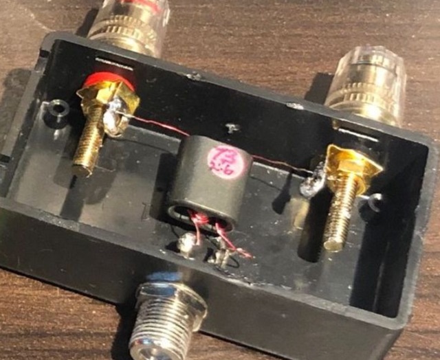
 This page provides information about building a Beverage antenna for hams. The article discusses using a 60m wire on the ground to create an effective antenna for amateur radio operators. Learn how to set up and optimize this type of antenna for better reception and communication. This describes a low-noise receiving Beverage antenna setup for low bands, using a N30 cup core transformer for 1:4 impedance matching (likely 50:200 Ohm), RG-58 feedline with heavy common-mode choking, and conduit for wire burial.
 -
 The most basic form of repeater receives communication on one frequency and re-transmits it on a different frequency, a process known as duplex communication. This capability significantly extends the range of handheld and mobile radios, as repeaters are typically situated at elevated locations with high-gain antennas and greater transmit power. Repeaters commonly operate with FM modulation on the VHF (30 MHz – 300 MHz) and UHF (300 MHz – 3 GHz) amateur bands, which are ideal for portable and mobile devices. Access to repeaters is often controlled by a CTCSS or PL tone, an inaudible signal that prevents the repeater from retransmitting background noise. This mechanism ensures efficient use of the frequency and prevents illegal continuous transmission. Canadian regulations, for instance, require an Advanced amateur radio license and an available frequency within the band to set up a repeater, each assigned a unique call sign and transmit frequency. Configuring a radio for repeater use involves knowing the repeater's transmit frequency, its receive frequency offset (e.g., -600 KHz for VHF or +5 MHz for UHF), and the necessary CTCSS tone. The article references resources like Repeater Book for locating repeaters and provides practical examples for initiating and concluding a basic repeater session, emphasizing clear identification and concise communication.
 -
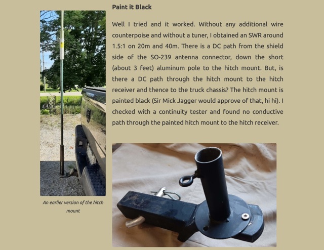
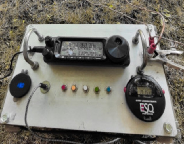
 A C-Pole Antenna for QRPxpeditions describes a DIY C-Pole antenna designed for QRP (low-power) expeditions, inspired by KF2YN’s ground-independent vertical model. After adjustments, it achieved a 1:1 SWR at 14.060 MHz, rising to 2.5:1 at 14.35 MHz. A choke balun, comprising 15 turns of RG8X around a 4†can, was essential for optimal performance. Compact and self-supporting, the antenna enables reliable communication with minimal setup. Contacts included stations across the U.S., and even a 4,600-mile connection to Spain using only 5 watts.
 -
 Delta loop antennas, particularly the 30 meter variant, offer unique advantages in terms of vertical polarization and omni-directional coverage. The construction process detailed by VE3VN highlights common mechanical and electrical challenges faced by amateur radio operators. Key design considerations include minimizing interaction with existing contest band antennas, achieving low elevation angles for DX chasing, and ensuring the antenna remains off the ground for agricultural clearance. The article provides specific measurements, such as the loop's height and feed point impedance, which are critical for optimizing performance. The use of NEC modeling software illustrates the importance of accurate resonance calculations, revealing how proximity to the tower affects both pattern and impedance. This practical account serves as a resource for hams looking to build effective antennas while navigating typical construction hurdles.
 -
 WB5NHL describes setting up a 160-meter antenna on a small suburban lot, where standard options like Beverage antennas and 1/4 wavelength verticals require extensive space and ground systems. Instead, Guy Olinger's Folded Counterpoise (FCP) provides a solution. The FCP minimizes ground losses by using a folded wire design, allowing effective antenna placement in limited space. The FCP, fed with an isolation transformer, enabled WB5NHL's first 160-meter antenna installation, offering improved performance despite space constraints.
 -
 Building some proper matching transformer for loop on ground and Beverage antennas
 -
 Learn how to construct a balanced Antenna Tuning Unit (ATU) for your ham radio equipment. Follow the instructions provided by Bengt, SM6APQ, to create a variable capacitor insulated from the ground for additional safety. Discover how to set up the ATU for the 20 to 10m band with proper spacing between coils. Use low power when adjusting the ATU for lowest SWR. Avoid using switches and opt for banana plugs for flexible connections. Visit the Creative Science Centre website for more information and resources on ATU construction.
 -
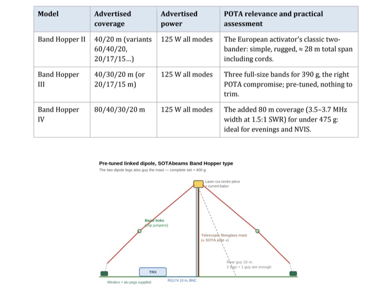 The resource discusses antenna families frequently utilized by _Parks On The Air_ (POTA) activators, focusing on the specific requirements for portable operations. It highlights the need for lightweight construction, rapid deployment, and sufficient efficiency to achieve the minimum **ten contacts** required for activation. The guide addresses adaptability to diverse field conditions, including the presence or absence of trees and varying ground surfaces. For each antenna type, the article provides a principle diagram, outlines its operational strengths, and details its inherent limitations. It also includes external links to practical field experiences, offering real-world context for each design. The POTA program, which involves setting up a complete station in a park, often within **thirty minutes**, underscores the antenna's critical role in successful activations.
 -
 The Beverage on Ground (BOG) antenna offers ham radio operators a compact alternative to traditional Beverage antennas, requiring less space and fewer support structures. This implementation, optimized for 1.8-7 MHz bands, describes ideal parameters: lengths of 60-90 meters, height of 2-10 cm above ground, and specific load resistances based on configuration. The article details experimental methods for determining optimal load resistance and presents matching systems to convert BOG impedance to 50 ohms. While less effective than classic 200-300 meter Beverages, the BOG provides directional reception in limited space, though performance varies with ground conditions and weather changes.
 -
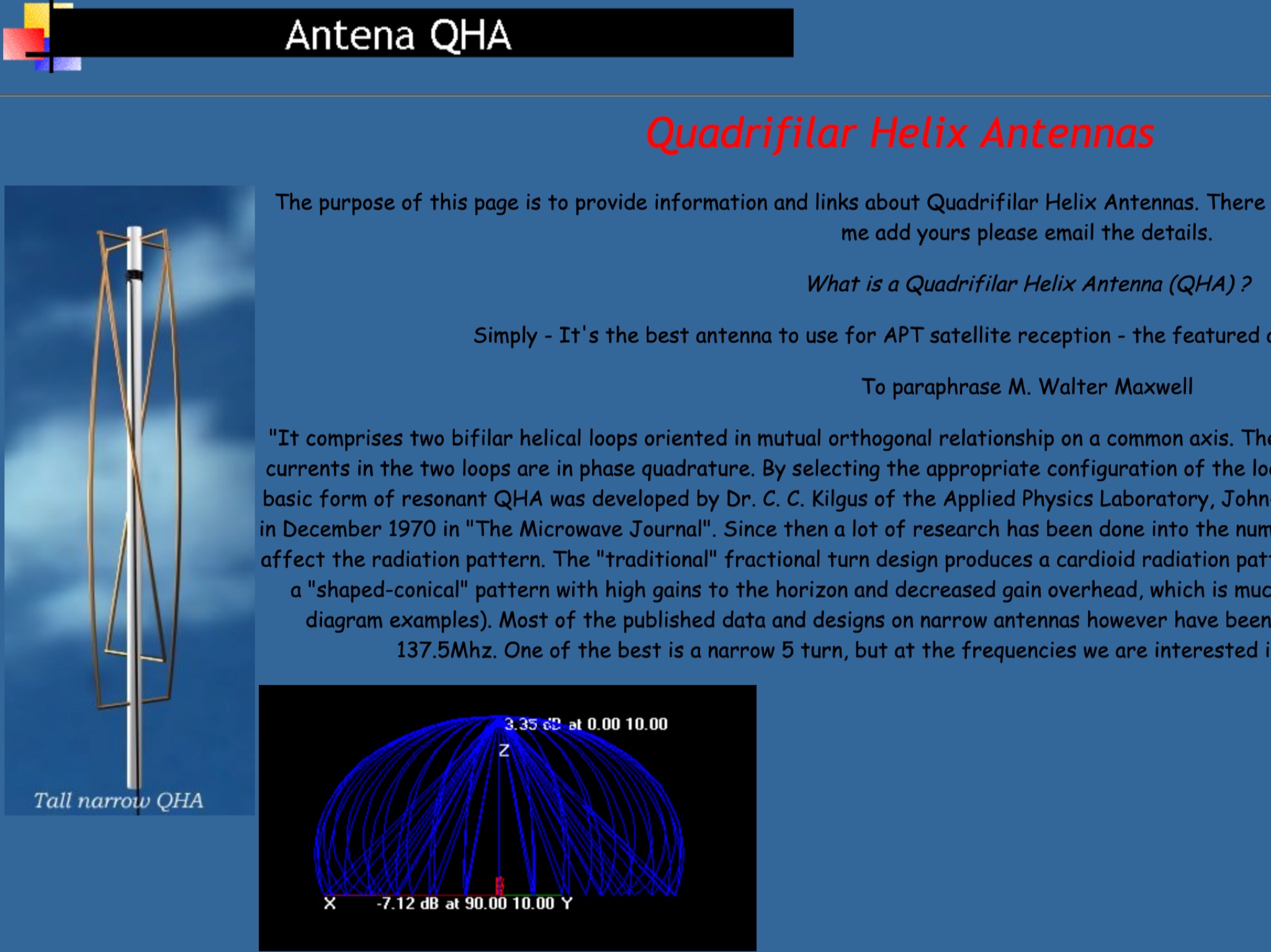 This page provides information and links about Quadrifilar Helix Antennas, the best antenna for APT satellite reception. It explains the basic design and configuration of QHA, including the research and developments that have been made over the years. The page offers insights into the radiation patterns and benefits of using QHA for APT ground stations, with examples of polar diagrams. If you are interested in learning more about QHA and its applications, this page is a valuable resource.
 -
 This article presents a novel Top Loaded End-Fed Half-Wave (TLEFHW) antenna design for 20-meter ham radio operation. The antenna features a compact 14-foot vertical radiator with a capacitance hat configuration, eliminating the need for radials or ground systems. Using EZNEC modeling and field testing, the design achieves a 1.5:1 SWR across the 20m band with a 4.11 dBi gain. Key features include quick deployment, lightweight construction, and directional radiation pattern with 110-degree beamwidth. The design, while requiring a 45-foot footprint due to the top hat, offers an effective portable solution for amateur radio operators seeking a no-ground, no-tuner 20m antenna option.
 -
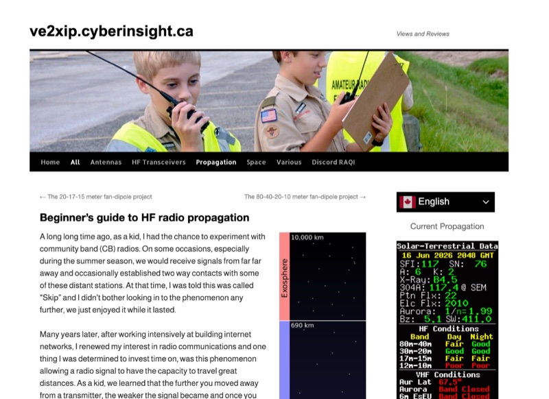 High Frequency (HF) radio propagation, particularly the phenomenon of "Skip," which enables long-distance radio contacts, is thoroughly explained for newcomers to the amateur radio hobby. The article begins by defining essential terms such as _radio signal_, atmosphere, troposphere, stratosphere, mesosphere, thermosphere, exosphere, and aurora, setting a foundational understanding for subsequent discussions. A significant portion of the content focuses on the ionosphere, identifying it as the primary driver of HF propagation. Its structure, including the D, E (E1, E2, E3), and F (F1, F2) layers, is detailed, along with how solar radiation influences these layers to refract radio waves back to Earth. The concept of "The band is opened!" is introduced, specifically noting refraction around **21 MHz**. The guide also touches upon ground waves, space waves, and temperature inversions affecting VHF/UHF propagation, contrasting them with the dynamic nature of ionospheric HF propagation. Factors like antenna polarization, takeoff angle, and the sun's solar cycle are mentioned as critical influences on signal path, with examples like 80-meter band propagation after sunset and 40-meter/20-meter bands offering near-constant propagation.
 -
 Cloverleaf antenna is a circular polarized antenna which is way better than the cheap dipole antenna that comes with video transmitters and receivers. The Cloverleaf is a closed loop antenna which the signal and ground wires are connected. The cloverleaf antenna has 3 loops at 120 degree apart, and they are titled at 45 degree to horizontal plane.
 -
 This page offers a tool for hams to design vertical antennas for portable use on different HF/VHF/UHF bands. Vertical antennas provide omni-directional transmission and reception, making them ideal for DX contacts. By adjusting the antenna's dimensions and viewing radiation patterns and VSWR charts, hams can optimize performance in various terrains. The tool also accounts for the impact of sloping ground on elevation radiation patterns. Perfect for hams looking to enhance their portable radio setups and improve long-distance communication.
 -
 Volda is specialized in telecom tower antenna line accessories such as cable hangers, coaxial jumpers, grounding buss bar kits, pole clamps.
 -
 This article explains the trick of how to shorten and lengthen pairs of radials to make a 2-band ground plane antenna. Included is a "Table of Multi-Band Possibilities" covering the range of 6 to 40 meters.
 -
 Integrating a _Software Defined Radio_ (SDR) into an existing ham radio setup involves connecting it with a standard transceiver (TRX), power amplifier (PA), and antennas. The core component is a splitter box that facilitates the connection between the TRX and the SDR, allowing for simultaneous operation without modifying existing equipment. In receive mode, the splitter ties the antenna inputs of both the TRX and a direct conversion receiver (DC RX) together. During transmission, the DC RX input is grounded via a fast telecom relay controlled by the transceiver's -SEND signal, incorporating a 10ms delay for safety. The splitter box includes a 3.7 dB input attenuator for impedance matching and acts as a protective fuse for the DC RX input. Ground loops are mitigated using common mode balun transformers, while the DC RX input is insulated with a broadband transformer. An audio switch box complements the setup, enabling users to listen to either the main transceiver, the SDR output, or both simultaneously. This configuration ensures noise immunity and safety, with the splitter housed in a screened box made from PCB material. On-air tests, such as the CQ WW 160m CW DX Contest, demonstrate the system's effectiveness, showcasing the SDR's ability to handle crowded band conditions with superior selectivity and dynamic range. The SDR's narrow bandwidth filters and waterfall display provide significant advantages, allowing operators to detect weak signals amidst strong interference. The integration of SDR with conventional radios offers enhanced operational flexibility and performance in challenging environments.
 -
 When installing a mobile antenna, optimal placement significantly impacts performance. Factors such as gain, antenna type, ground plane availability, mounting style, and environment must be considered. Antenna designs, such as 1/4 wave and 5/8 wave, have distinct radiation patterns ideal for specific settings—urban areas or flat terrains, respectively. Ground plane size requirements differ by frequency, impacting effectiveness. Among vehicle mounting options, the car roof center provides the best ground plane and minimal obstruction, ensuring peak performance, especially at higher frequencies like 800 MHz.
 -
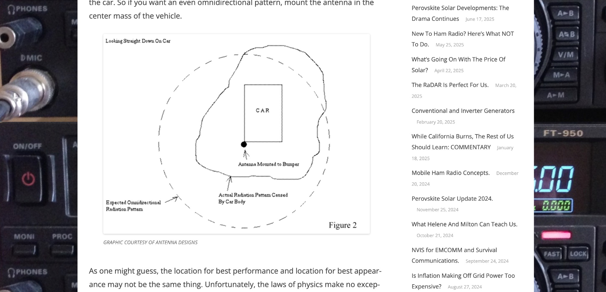 Off Grid Ham discusses the benefits of mobile ham radio operation in addition to fixed or semi-fixed base stations. The article highlights the challenges of antenna placement on vehicles, emphasizing the importance of a good ground plane for optimal performance. Tradeoffs between performance and appearance are inevitable, especially with modern vehicles that have plastic body panels. Bonding the coax shield to the car frame is often necessary to establish a good ground plane. Mobile ham radio operation is a valuable option that fills in the gaps left by fixed stations, offering flexibility and convenience for hams on the go.
 -
 This resource details the construction and performance of a compact broadband magnetic loop antenna designed for portable receiving applications with devices like the _ATS MiniRadio_. The antenna utilizes approximately 3 meters of 0.5–1 mm copper wire wound in two turns on a rhomboidal wooden frame, measuring 50 cm by 70 cm. It connects via a modified 9:1 unun, where the primary center tap is isolated from ground to improve common-mode noise rejection. The design provides untuned operation across a frequency range from the longwave band up to approximately 25 MHz. Performance characteristics include observable directivity for noise suppression and the ability to connect directly to a radio or via a 50 coaxial cable for remote operation. The article specifies the unun's 3:1 turns ratio and its SMA output for connectivity. The methodology focuses on practical construction and observed reception quality.
 -
 This is a theoretical look at propagation on 630-Meters and 2200-Meters using ray tracing software. It expands on the brief discussion in the ARRL Handbooks. The Earth's magnetic field affects 630-Meter and 2200-Meter band propagation. Lower ionization reduces absorption, aiding low-frequency propagation. Differences exist between bands, limited daytime sky-wave propagation. Sunrise/sunset show promise, yet mechanisms are unclear. Ducting possible at night in specific conditions. Negative ions enhance propagation. Inefficient antennas and high man-made noise are anticipated. Groundwave propagation is significant on 2200-Meters.
 -
 This article explores Beverage antennas, a type used for low-frequency radio reception. Despite the mystique, they are relatively simple wire antennas placed near the ground. Their key benefit is improved signal-to-noise ratio by rejecting unwanted signals. While lengthier antennas offer better reception, even shorter versions (around 200 feet) can improve DX reception compared to traditional antennas.
 -
 A guide to constructing a simple quarter-wave ground plane antenna, detailing design principles and providing dimensions for VHF/UHF bands
 -
 Operating amateur radio satellites presents unique challenges, particularly concerning antenna design and signal propagation. Juan Antonio Fernández Montaña, EA4CYQ, recounts his three-year journey into satellite communication, starting with initial guidance from EB4DKA. His early experiments involved a portable 1/4 wave VHF antenna with four 1/4 wave ground planes, designed for hand-held use to adjust polarity. This setup, paired with an FT-3000M transceiver, allowed full-duplex operation on **VHF** transmit and **UHF** receive, proving effective for early contacts on satellites like AO27, UO14, and SO35. EA4CYQ's experience highlights the critical role of coaxial cable loss and antenna polarization. After encountering significant signal degradation with longer RG213 runs, he experimented with a 1/2 inch commercial cable, noting improved reception but persistent fading due to varying satellite polarities. This led to the construction of an **Eggbeater II** antenna, an omnidirectional UHF design offering horizontal polarization at the horizon and circular right polarization at higher elevation angles. Subsequent modifications resulted in the directional **TPM2** antenna, which provided sufficient gain for LEO satellites with a wide 30-degree lobe, enabling consistent contacts from his home station. The article concludes with practical insights on the performance of the Eggbeater II for both UHF and VHF, and the TPM2 for UHF, emphasizing their utility for portable and fixed operations. EA4CYQ's journey underscores the iterative process of antenna development and the importance of adapting designs to overcome real-world propagation challenges in satellite communications.
 -
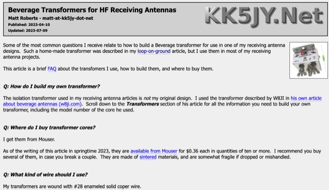 This FAQ covers building and buying transformers for loop-on-ground and Beverage antennas. Building one uses ferrite cores and thin wire. Buying is an option, with the DX Engineering BFS-1 being recommended. These transformers isolate the antenna from the cable to prevent unwanted signal pickup.
 -
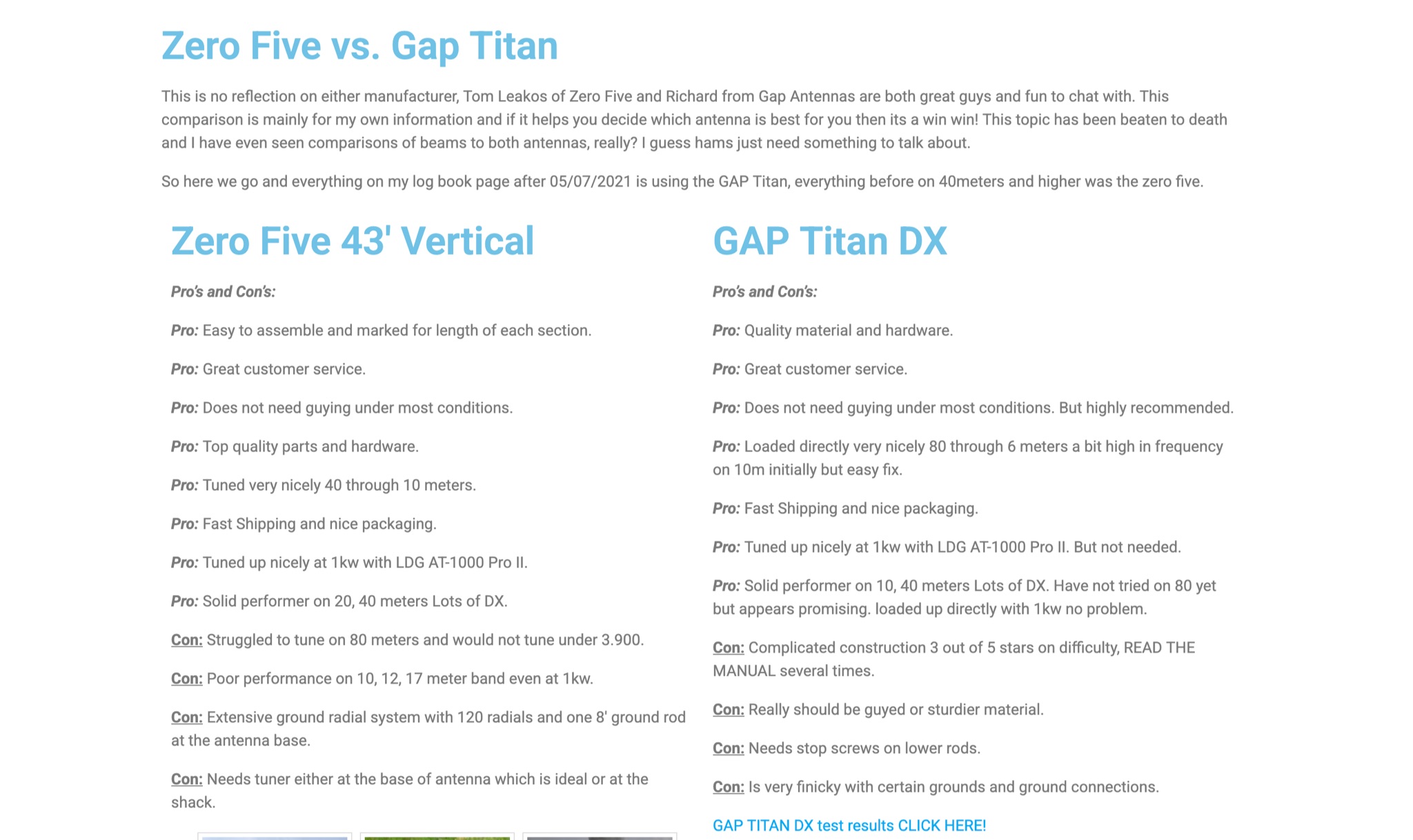 This page provides a detailed comparison between the Zero Five and Gap Titan ham radio antennas. The author shares their personal experience with both antennas, highlighting pros and cons for each. They discuss aspects such as ease of assembly, customer service, tuning capabilities, performance on different bands, and the need for grounding and tuning. The comparison aims to help readers make an informed decision on choosing the best antenna for their needs, based on real-world usage scenarios and feedback.
 -
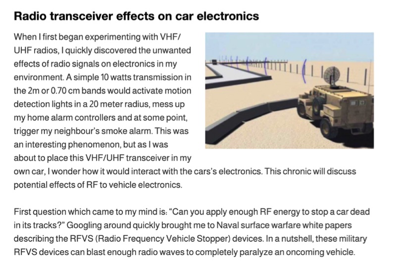 Illustrates the potential for radio frequency (RF) energy from amateur transceivers to interfere with vehicle electronics, drawing parallels to military _Radio Frequency Vehicle Stopper_ (RFVS) technology. The resource details personal experiences with VHF/UHF signals activating household devices and then pivots to the complexities of RF interaction with automotive systems, noting the development of multi-frequency RFVS (MFRFVS) to overcome vehicle-specific vulnerabilities. It highlights that while car manufacturers conduct RF immunity tests, the rigor varies, with luxury brands likely performing more extensive evaluations than others who merely meet minimal certification. The article explores practical considerations for mobile amateur radio installations, suggesting antenna placement over the car, using lower power output, and proper grounding to mitigate adverse effects. It acknowledges the lack of comprehensive data on RF/vehicle combinations but emphasizes that adherence to these basic principles can reduce risks. The author shares observations of unexplained car computer codes in a 2002 SUV, speculating on potential RF induction. Concerns are raised about the increasing complexity and interconnectedness of modern car electronics, including Bluetooth, remote access, and electronic control systems for critical functions like steering and braking. The article points out the diminishing space for third-party installations in contemporary vehicles and references the ARRL's stance on auto manufacturer policies regarding amateur radio installations, which generally advise against them.
 -
 Demonstrates the design and modeling of a **160m** vertical antenna, dubbed the "WindoVert," specifically for urban amateur radio operators with limited space. The resource covers the theoretical underpinnings of antenna height and radiation patterns, using EZNEC software to analyze current distribution and 3D radiation patterns for various configurations, including a Marconi-style "T" antenna. It details the integration of existing antenna components, such as a Carolina Windom balun and line isolator, into the new vertical setup, and the practical measurement of feedpoint impedance using an antenna analyzer. The article further explores the challenges of achieving low-angle radiation on Top Band, emphasizing the critical role of radial systems and mitigating ground loss. Author VE1ZAC presents EZNEC models illustrating the impact of lumped components and discusses the practical considerations of resonant frequency adjustment and impedance matching for **QRP** operation. The text details the calculation of required loading coil inductance and capacitance, and shares field results, including successful DX contacts on 160m and unexpected excellent performance on 30m.
 -
 The Gemini Amplifier Remote Control software operates on Windows 7 and above, facilitating remote management of the Gemini HF-1K and DX-1200 amplifiers. Users connect via Ethernet, configuring the amplifier's IP address through the front panel. The software allows seamless band and antenna selection, saving settings for each band without requiring transmission. Integration with _OmniRig_ from Afreet Software, Inc. enables automatic band adjustments based on the radio's frequency changes. Users can configure serial or virtual serial connections, with tracking options accessible through the ribbon bar. The software supports speech functionality, enhancing accessibility for operators. Firmware updates, such as version 2.5Ee, introduce features like background datalogging and power output control, uploaded via FTP. Version 1.2.0 allows users to offload internal parameter data for support purposes. The firmware upload process requires the amplifier's IP address and port 21, taking approximately 90 seconds. Users are encouraged to upgrade to the latest firmware for improved performance and remote diagnostics.