Search results
Query: par antenna
Links: 551 | Categories: 9
Categories
- Manufacturers > Antenna Parts
- Shopping and Services > Antenna Parts
- Shopping and Services > Antennas
- Radio Equipment > Reviews and Comparisons
- Shopping and Services > Regional > Asia
- Radio Equipment > HF Portable Antenna > Buddipole
- Manufacturers > Antennas > HF > Magnetic Loop
- Shopping and Services > Regional > Europe > UK
- Antennas > ZS6BKW
-
 A fractional bandwidth of up to 30:1 characterizes spiral antennas, making them highly effective across a very wide frequency range, often from 1 GHz to 30 GHz. The resource details two primary types: the **Log-Periodic Spiral Antenna** and the **Archimedean Spiral Antenna**, defining each with specific polar functions and illustrating their planar configurations. It explains that spiral antennas are typically circularly polarized, with a Half-Power Beamwidth (HPBW) of approximately 70-90 degrees, and a peak radiation direction perpendicular to the spiral plane. The content elaborates on critical design parameters affecting radiation, including the total length (outer radius) for lowest frequency, the flare rate ('a' constant) for optimal radiation versus capacitive behavior, the feed structure (often an infinite balun) for high-frequency operation, and the number of turns (typically 1.5 to 3 turns). It also discusses the theoretical impedance of 188 Ohms for Log-Periodic spirals, derived from Babinet's Principle, noting actual impedances are often 100-150 Ohms. The article presents a simple construction method for an Archimedean spiral, demonstrating VSWR and efficiency measurements. Measurements from a constructed spiral antenna show a VSWR that is fairly constant across the band, albeit with a mismatch loss of about 3 dB. The antenna efficiency remains around -5 dB (31.6%) across its operating range, indicating a decent wideband radiator despite opportunities for optimization.
 -
 This article compares two commercial vertical antennas for the 4-meter amateur radio band: the Watson WVB-70 half-wave and the Sirio CX4-71. The Watson measures 2.03m in length, costs around £40, and exhibited adequate performance but required additional waterproofing after rain affected its VSWR readings. The longer Sirio CX4-71 (3.02m) performed noticeably better, delivering signals approximately 2 S-points stronger than the Watson. The Sirio demonstrated high build quality, a stable 1.2-1.4:1 VSWR, and weather resilience, though minor VSWR fluctuations were observed during rain and frost. Both antennas are half-wave designs requiring no ground plane radials.
 -
 This calculator is designed to give the horizontal length of a particular dipole including Tees, antenna, or one side of it, for the frequency chosen. Enter the desired frequency and select the desired calculation from the drop box
 -
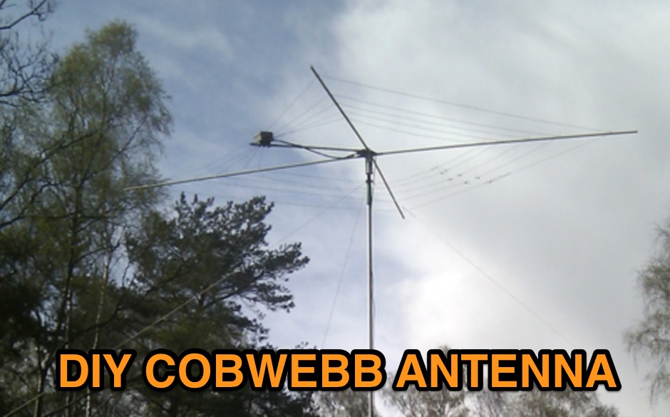 A DIY guide to build your own compact multiband HF antenna based on the G3TXQ version using a 1:4 balun. This article includes the full part list and instructions to assembly, including the center plate.
 -
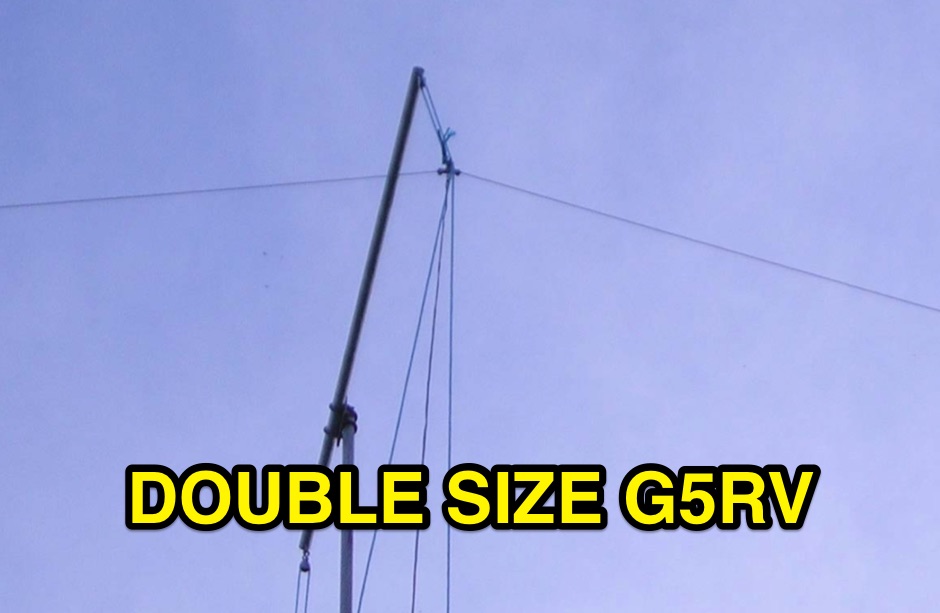 Building the double size G5RV antenna, part list, assembly part, dimensions and assembly instruction in a pdf document
 -
 The essentials of the parabolic reflector or dish antenna and its theory and design for high performance applications such as satellite transmission and reception as well as microwave links.
 -
 HAM-IV antenna rotor repari and restore
 -
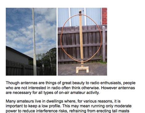 Antennas for restricted lots, apartments and indoor antennas by VK3YE
 -
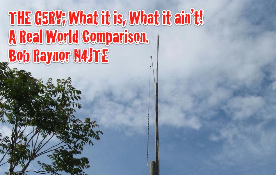 A very interesting blog article on a real world comparison on the popular multiband wire antenna, the G5RV, by Bob Raynor N4JTE
 -
 Skycraft Parts & Surplus, Electronic Surplus Store in the Southeast, antenna parts, wires.
 -
 Presentation by AC8GY on classic G5RV Antennas and other horizontal dipoles, the popular G5RV, ZS6BKW, dipole fan, Alpha-Delta DX-CC and a trap dipole are modeled in EZNEC and compared.
 -
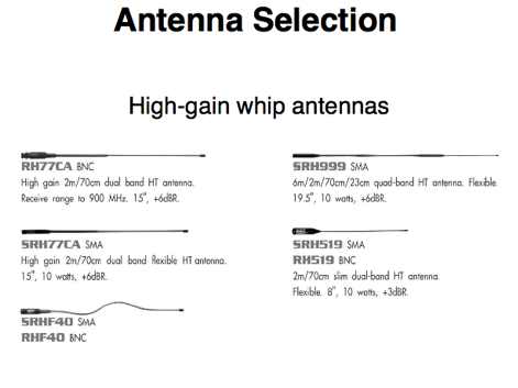 The document titled 'Extending the Range of Your Handheld' by WG7S is a guide on how to extend the range of your handheld VHF UHF transceiver by using an external antenna. It provides information on comparing popular models, selecting the right antenna, and resources for amateur radio antennas.
 -
 The 10-minute, 25-second video demonstrates making a QSO via the VO-52 amateur radio satellite, focusing on real-time Doppler shift correction. It features Simon, 2E0HTS, operating a Yaesu FT-847 transceiver and a homebrew dual-band Yagi antenna, specifically a 10-element 435 MHz Yagi for uplink and an IO Loop for 145 MHz downlink. The video visually details the operator's technique for continuously adjusting the uplink frequency to compensate for the satellite's changing velocity relative to the ground station, a critical aspect of successful satellite communication. The demonstration highlights the practical application of Doppler compensation, showing the operator tuning the transmit frequency to maintain a stable received signal from the satellite. This approach contrasts with systems employing automatic Doppler correction or full-duplex operation, providing insight into manual frequency management for satellite passes. The video serves as a direct, observational guide for hams interested in LEO satellite operations, particularly those using non-tracking, manually tuned setups.
 -
 Isolation vs antenna separation an interesting article by WA6ILQ
 -
 Dish antenna and its theory and design for high performance applications such as satellite transmission and reception as well as microwave links. Parabolic Reflector Antenna: Dish Antenna The parabolic reflector antenna which is often called the dish antenna provides an antenna solution applicable for VHF and above where high gain and directivity are needed for all type of radio communications and radio reception.
 -
 The X80 multi-band HF vertical antenna, a commercial iteration of the Rybakov design, exhibits a physical length of 5.5 meters, or approximately 18 feet, and is constructed from aluminum tubing. It operates as a non-resonant vertical, requiring an external antenna tuner for impedance matching across its intended operating frequencies. The antenna's design incorporates a 1:4 UNUN at its base, facilitating a nominal 50-ohm feed point impedance for the coaxial cable. Performance observations indicate effective operation on 40 meters, 20 meters, 15 meters, and 10 meters, with reduced efficiency on 80 meters and 160 meters due to its relatively short electrical length for these lower bands. Comparative analysis with a G5RV dipole and a half-wave end-fed antenna reveals the X80 offers a lower take-off angle, beneficial for DX contacts, particularly on the higher HF bands. Field tests conducted with an Icom IC-706MKIIG transceiver and an LDG AT-100ProII autotuner demonstrate the X80's ability to achieve acceptable SWR across 80m through 10m. The antenna's compact footprint and ease of deployment make it suitable for restricted spaces or portable operations, though its performance on 80 meters is noted as a compromise compared to full-size resonant antennas.
 -
 A comparison of multiband dipoles, including jumpered dipole versus fan dipole antennas, dipole fed by ladder line, resonant dipoles antennas. ARRL lab notes
 -
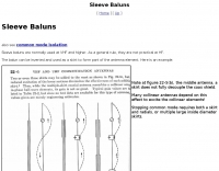 Sleeve baluns are normally used at VHF and higher. As a general rule, they are not practical at HF. The balun can be inverted and used as a skirt to form part of the antenna element
 -
 The GM4JJJ VHF and EME pages document David's extensive work in Earth-Moon-Earth (EME) communication, specifically on the 144 MHz band, and his involvement in amateur radio astronomy. The resource details his station setup and operational experiences, providing insights into the technical challenges and rewards of bouncing signals off the moon. It offers a glimpse into the specialized equipment and techniques required for successful EME contacts, a niche but highly rewarding aspect of amateur radio. David's content shares practical applications and field results from his EME endeavors, which can be particularly useful for hams contemplating or actively pursuing moonbounce operations. The information, while not a step-by-step guide, implicitly compares the complexities of EME with more conventional VHF/UHF operations, highlighting the significant power and antenna gain necessary to overcome path losses. This resource serves as a testament to the advanced capabilities achievable in amateur radio.
 -
 Demonstrates various practical amateur radio projects and technical discussions through video episodes. One episode details cutting and retuning a _1/4 wave shorted stub_ from 101.7 MHz to 107.5 MHz to safeguard a transmitter's driver stage, alongside insights into advanced _160-meter antenna systems_ like eight-circle arrays and beverage antennas. Another segment covers upgrading firmware on an _ATS-20+_ receiver using AverDudes for improved display and functionality, and a detailed guide on using D-Star DR mode on an _ICOM ID-52A_ for international repeater programming. Additional content includes a deep dive into _OpenHamClock_ as a potential replacement for the HamClock project, updates on _Raspberry Pi 5_ running Trixie OS, and a review of the Choyong LC90 Internet radio with AI integration. The series also features "Ham College" episodes, which meticulously prepare viewers for the Technician Exam by covering topics such as antenna and transmission line measurements, SWR interpretation, and the functions of basic electronic components like rectifiers, relays, and transistors. Practical advice on coaxial cable characteristics, dummy loads, and proper soldering techniques is also provided.
 -
 The collinear J-Pole, often known as the Super-J, does improve the behavior over a regular J-Pole. As many attest, there is an advantage when vertically combining 1/2 radiating sections to have a bit of separation between the half-wave end points. The Super-J has very little separation between the two half-wave radiators.
 -
 A project that describes a build a multiband wire beam antenna. A 3 band single feed moxon antenna for 20,15,10 meters.
 -
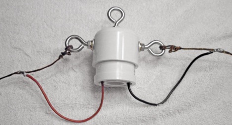
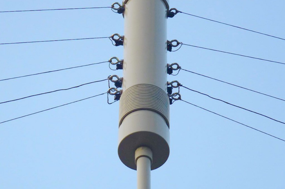
 Protecting amateur radio equipment from transient overvoltages requires robust lightning and surge protection, which is the focus of Electronic Specialty Products. The company provides various devices, including coaxial lightning arrestors for antenna feedlines and surge protectors for AC power lines and data circuits. These devices are engineered to divert high-energy surges, such as those caused by direct or indirect lightning strikes, away from sensitive transceivers, amplifiers, and computer components, thereby preventing catastrophic damage. Key products include the _Coaxial Lightning Protector_ series, designed for various impedance levels and frequency ranges up to 3 GHz, and the _AC Line Surge Protector_ for shack power distribution. Effective deployment of these protection devices can significantly reduce the risk of equipment failure and ensure operational continuity during severe weather. For instance, a properly installed coaxial arrestor can handle peak currents of **20 kA**, while AC line protectors offer clamping voltages typically below 400V. Comparing different models reveals varying levels of insertion loss and return loss, with some coaxial units exhibiting less than 0.1 dB loss at 500 MHz, making them suitable for high-performance HF and VHF/UHF operations. Integrating these components into a comprehensive grounding system is crucial for achieving maximum protection against both common-mode and differential-mode surges.
 -
 C-Poles for 20m and 6m, it is a folded half-wave dipole with an asymmetrical tapped 50-Ohm-point in the lower part of the antenna. Design hints by DK7ZB
 -
 Examines the historical role of telegraphy within Canadian railway operations, detailing the evolution of communication systems crucial for train dispatch and coordination. It covers the technical substance of railway telegraphy, including equipment, operational procedures, and the personnel involved, such as agents and operators. The resource provides insights into the **F59PH locomotive** history, development, and components, alongside diagrams of various parts like antennae and traction motors. The content also explores the practical application of these systems by documenting specific railway events, such as the CPR Galt Sub operations from 1895-1971 and GO Transit's operational history. It includes photo galleries, schematics, and diagrams of locomotives and cab cars, offering a visual and technical comparison of different railway equipment. The site also features information on **GO Transit** rolling stock, including MP40s and commuter coaches, providing a historical context for railway communication and transportation.
 -
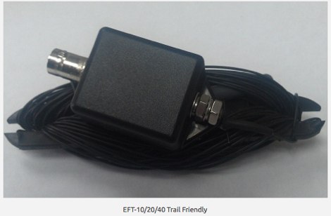 LnR Precision Inc. is a North Carolina based company that specializes in Par EndFedz amateur radio antennas and MantiZ QRP Transceivers. Their most popular products include End-Fed QRP portable antennas and HF FX Series QRP Transceivers.
 -
 Delta loop antennas for 40 meters plans and comparison of some models
 -
-
 A system designed to automatically tune small transmitting magnetic loop antennas, particularly beneficial for **contest operations** where rapid frequency changes are common. The core of the system involves a PC-based control application, AutoCap, written in C#, which monitors antenna SWR via an external meter and commands a motor interface to adjust the loop's variable capacitor. The software is compatible with Windows and Linux via the Mono framework, offering a graphical user interface for monitoring system status, SWR, power, and motor commands. Key components include one or more magnetic loop antennas equipped with DC or stepper motors for capacitor adjustment, an SWR meter with data output (such as the Telepost LP-100A or a homebrew serial/USB SWR meter), the AutoCap PC software, and a motor interface. The most effective motor interface utilizes an **Arduino-based controller** with custom firmware, providing precise control over both simple DC motors and stepper motors, and supporting features like motor braking for finer adjustments. The system allows for configurable SWR thresholds, pulse widths, and motor effort settings to optimize tuning speed and resolution. Optional radio integration provides frequency hints, enabling the algorithm to learn the relationship between motor actions and resonant frequency, thereby speeding up initial tuning responses. The software also supports antenna profiles, allowing operators to save and recall specific configurations for different loops, including accumulated frequency hint data.
 -
 The HF horizontal loop has been around for many years now. This article includes a YouTube video and discusses the reasons for looking at this antenna, its design, and its installation. There are some on-air comparisons against three regular double bazooka (coax) dipoles and the Par SWL End-Fed antenna.
 -
 A 2 element 40 meters band parasitic delta loop antenna project with pictures and details
 -
 Designing and constructing portable wire antennas for HF operations, this resource explores several configurations including the _foldback dipole_ for space-constrained setups and an inductively shortened dual-band dipole for 20m and 40m. It details the calculation of inductance for shortened elements, providing a Visual Basic 6.0 program screenshot that illustrates determining coil parameters like turns and length for a **25.5 uH** inductor. The document emphasizes practical considerations such as adjusting wire lengths for optimal SWR, noting that a dual-band dipole achieved SWR below 2:1 on both 20m and 40m, with careful adjustment bringing it under 1.5:1. Further, the resource describes a half-wave antenna matched with a coaxial stub, a method often referred to as the _Fuchskreis_ in German amateur radio circles, to transform the high feedpoint impedance to 50 Ohms. This monoband solution, for a 20m application, uses a stub length of **2.98m** (0.216 lambda multiplied by coax velocity factor) and a shorted stub of approximately 48cm. The coaxial stub design is highlighted for its resilience to ground proximity, allowing it to be rolled up or laid on the ground with minimal SWR impact, making it highly suitable for portable QRP operations.
 -
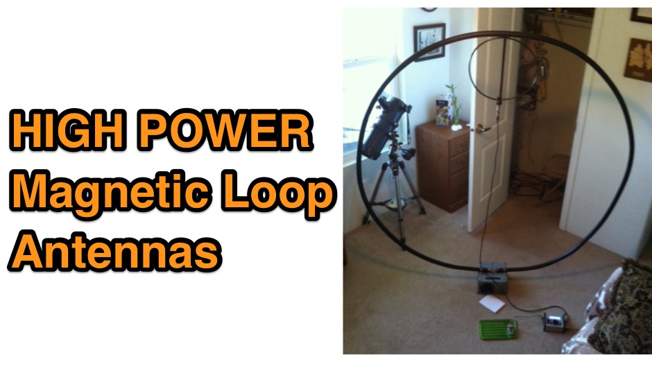 Magnetic Loop Antennas for The Radio Operator with Limited Space, a two part series of articles on how to construct a magnetic loop antenna, including directions on selecting high voltage tuning capacitor
 -
 The page discusses the concept of a 2-element Parasitic Ground Plane antenna for the 40-meter band. It includes a conversation between amateur radio operators discussing modeling results and design considerations for the antenna. The author shares insights on radial configurations and the impact on antenna efficiency and pattern.
 -
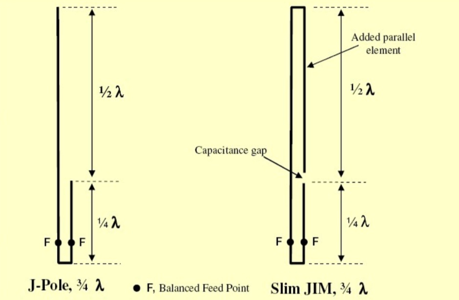 Build the Slim JIM Antenna, a unique VHF Antenna with gain over a J-Pole Jose I. Calderon, DU1ANV
 -
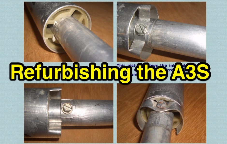 Refurbishing a Cushcraft A3S, by George Szymanski, DU1GM
 -
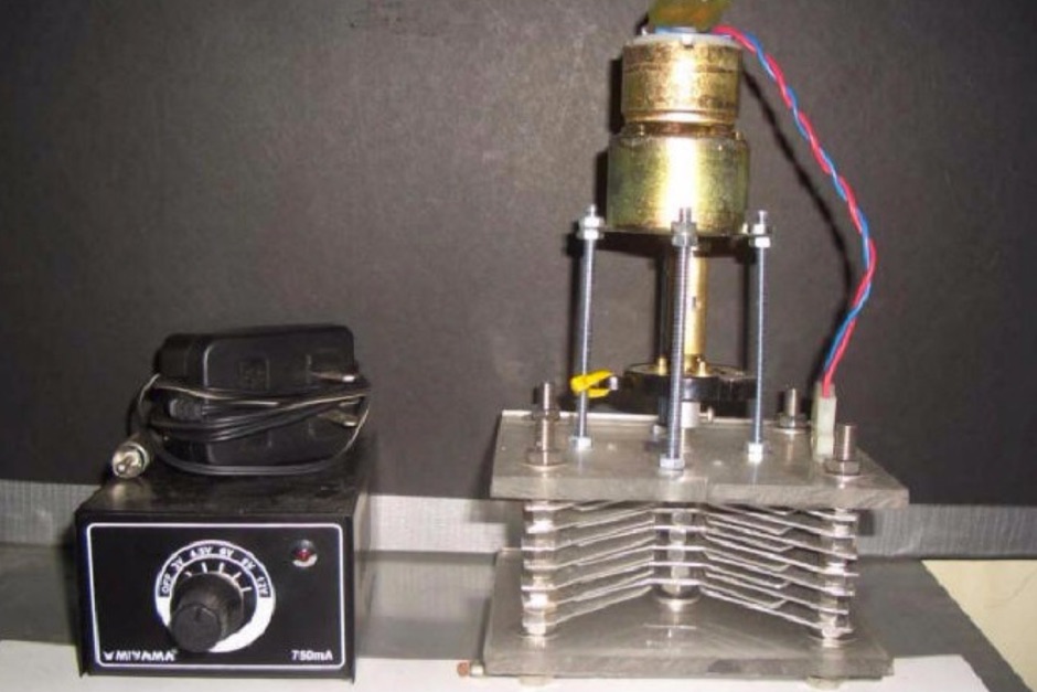 Magnetic Loop Antenna for 20/15m with Remote Tuning by George Szymanski
 -
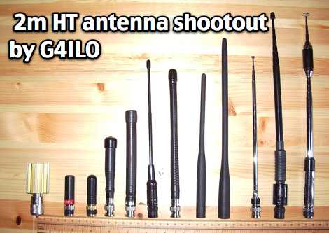 G4ILO compares popular antennas for 2 metre band handhelds so as to see how much you lose using a small inconspicuous antenna or how much you gain by using a long antenna.
 -
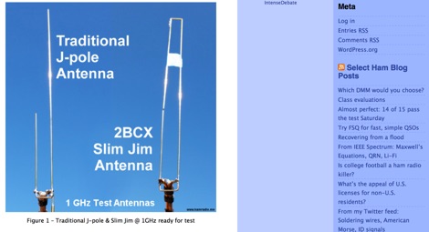 A comparative article on performance differences between Slim Jim antennas versus J-Pole antennas
 -

-
 The early 20th century saw significant advancements in wireless communication, culminating in the first successful transatlantic radio signal. This historical account details Guglielmo Marconi's pioneering efforts, from his initial experiments with electromagnetic waves to his patented wireless system in 1900. It describes the technical challenges of long-distance radio transmission, particularly the prevailing belief that radio waves would be lost due to the Earth's curvature over vast distances. On December 12, 1901, Marconi established a receiving station in Newfoundland, Canada, utilizing a _coherer_ and balloons to elevate the antenna. Signals, consisting of the Morse code letter "S" (pip-pip-pip), were transmitted from Poldhu, Cornwall, England. The successful reception of these faint but distinct signals across **1,700 miles** confirmed Marconi's theories, marking an epoch in communication history. This achievement demonstrated the viability of global wireless communication, paving the way for future developments in radio technology.
 -
 Mitigating RF noise in a mobile operating environment, particularly within a _Jeep TJ_ vehicle, presents unique challenges due to the vehicle's electrical system and chassis characteristics. This resource details practical methods for identifying and suppressing various forms of radio frequency interference (RFI) that can degrade receiver performance for both CB and amateur radio transceivers. It covers common noise sources such as ignition systems, alternators, fuel pumps, and computer modules, explaining how these components generate broadband or specific frequency noise that impacts radio communications. The guide offers actionable solutions, including proper grounding techniques, the strategic use of ferrite beads and toroids on power and data lines, and the installation of bypass capacitors. It discusses the effectiveness of different filtering strategies for DC power lines and antenna feedlines, illustrating how a clean power supply and shielded cabling can significantly reduce conducted and radiated noise. The information presented helps operators achieve a lower noise floor, improving signal-to-noise ratio and enabling clearer reception of weak signals, which is crucial for effective mobile DXing or local ragchewing.
 -
 Operating magnetic loop antennas requires careful consideration of RF safety, particularly regarding near-field magnetic field intensity. This resource presents calculations for magnetic field strength (H-field) at various distances from a magnetic loop, emphasizing that the H-field is significantly higher than the E-field in the near-field region due to the inductive nature of the radiating element. It provides specific formulas and examples for determining safe operating distances based on power levels and loop dimensions, crucial for compliance with RF exposure limits. The analysis compares calculated H-field values against FCC and ICNIRP maximum permissible exposure (MPE) limits for controlled and uncontrolled environments. It demonstrates that even at QRP power levels (e.g., 5W), the H-field can exceed MPE limits within a few feet of the antenna, necessitating greater separation distances than often assumed for electric field considerations. The practical application of these calculations helps amateur radio operators configure their stations to ensure personnel safety and regulatory compliance when deploying compact, high-Q magnetic loop antennas.
 -
 The resource details the construction of a multiband trap-style Inverted-V antenna designed for operation on 3.5 MHz, 7 MHz, 14 MHz, 21 MHz, and 28 MHz. It presents specific winding data for the traps, including the number of turns, wire gauge, and coil former dimensions, crucial for achieving resonance on the target bands. The document provides a parts list and a diagram illustrating the antenna's physical layout and trap placement. It outlines the process for building the traps using PVC pipe formers and specifies the required capacitor values for each trap. The design emphasizes a practical approach to achieving multiband operation with a single feedline, a common goal for HF operators with limited space. The document includes a table with antenna segment lengths for each band, allowing for precise replication of the design. It also offers insights into tuning and adjustment, ensuring the antenna performs optimally across the designated amateur radio bands.
 -
 This is another alternative home-brew center connector for a dipole. The parts used are common PVC accesories found at the home supply store.
 -
 Hi-Z Antennas offers specialized high-impedance receiving systems, primarily focusing on phased vertical arrays for HF reception. Their product line includes preamplifiers designed for shortened vertical antennas, featuring optimized 15dB gain and array-matched characteristics. These components are engineered to enhance weak signal reception and improve signal-to-noise ratio across the HF spectrum. The company provides controllers for managing multiple vertical elements in a phased array configuration, enabling directional reception patterns. These systems are particularly effective for mitigating local noise and interference, a common challenge in urban and suburban operating environments. Specific offerings include solutions for 160-meter and 80-meter bands, addressing the unique requirements of low-band DXing. Technical details often reference components like the 2N3866 transistor in preamp designs and discuss concepts such as out-of-band attenuation. The focus remains on optimizing receiving antenna performance through impedance matching and active amplification, rather than transmit capabilities.
 -
 Testing performances of indoor antenna. A comparison of a magnetic loop antenna vs a classic wire dipole done using wsprlite on 30 meters band.
 -
 A magnetic loop antenna for the VHF band, featuring a high gain that can be compared to a quarter wave vertical antenna
 -
 A 38-foot Tristao Tower, similar to the U.S. Tower HDX538, was installed twice by the author, first in 1980 and then reinstalled in 1989. The resource details the challenges of self-performing heavy construction tasks like breaking concrete and digging a 3' x 3' x 6' deep footing, contrasting it with hiring professionals for the second installation. It highlights the financial and physical costs associated with DIY tower foundation work, noting a rebar cage cost of $65 in 1980 versus $150-$175 today, and the expense of tools for bending rebar. The content emphasizes the critical importance of obtaining building permits, recounting how a permit in Buena Park, California, nullified a neighbor's complaint about TVI. It also discusses the necessity of adhering to local building codes, such as the 1975 UBC and the subsequent 1985 UBC recertification requirement, which reduced the allowed antenna wind loading from 30 square feet to 20 square feet for the author's _KT34A_ Yagi. The footing depth also increased from 6 feet to 6.5 feet under the newer code. Practical advice includes hiring licensed contractors for specialized work, delaying antenna installation for a month after raising the tower, and verifying buried utilities before any excavation. The author provides specific examples of utility location services like _DigAlert_ in California, underscoring the legal and safety implications of neglecting this step. The narrative is grounded in personal experience, offering a realistic perspective on tower projects.
 -
 The fan dipole antenna as an alternative to the paralled dipole antenna, to achieve a larger bandwidth and a better tuning by decreasing elenment influences.A project based on the W6HDG original concept.