Search results
Query: do antenna
Links: 699 | Categories: 7
-
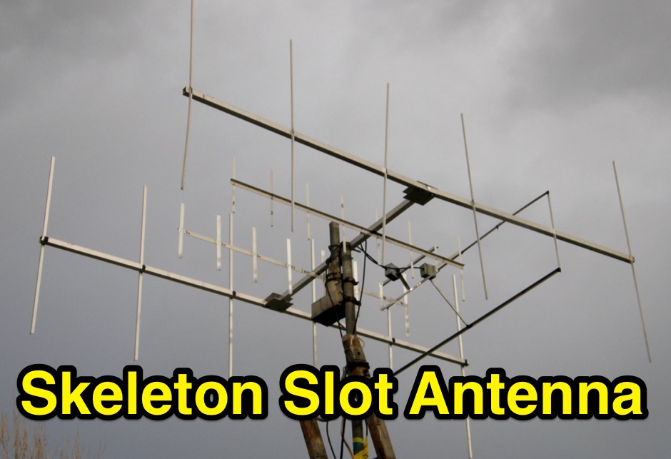 The skeleton slot antenna design was developed in the UK for TV use soon after WW2. This document describe and adapted version for the 2 meter band
 -
 A small random wire antenna tune that can tune from 40 to 10 meters bands.
 -
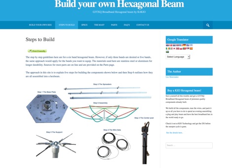 A web site dedicated to hex beam homebrewing. The hexagonal beam has become a wildly popular antenna. It is a directional antenna that provides great performance and does not require a full scale, expensive tower.
 -
 The 1960s mobile/base antenna returns, double G Whip for base use.
 -

-
-
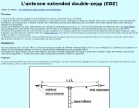
 A page in french dedicated to the double bazooka antenna, with a short history of this antenna model and main characteristics including a comparison versus the dipole antenna and formulas to determine elements size.
 -
 Demonstrates the construction and implementation of a **two-element phased vertical array** for 40 meters, utilizing _Christman phasing_ techniques. The author, W4NFR, details the process from building individual 1/4-wave aluminum verticals to integrating them into a phased system. The resource covers antenna spacing of 32 feet, elevated radial design, and the critical steps for tuning each vertical to achieve a 1.1:1 SWR before combining them. It also provides insights into calculating precise coax lengths for feedlines and the phasing delay line, emphasizing the use of an MFJ-269 Antenna Analyzer for verification. The finished system exhibits good front-to-back nulls, with an overall SWR ranging from 1.6:1 to 2.2:1, which is managed by an antenna tuner. The project includes detailed photos of the relay box, showing 12 VDC relays capable of handling 5KV, and the control box in the shack for switching between three different antenna pattern configurations. Static bleed-off chokes are incorporated for protection, and the construction emphasizes robust weatherproofing for outdoor elements.
 -
 The GM3VLB Poor Man's Antenna Analyser
 -
 A 5/8 wave antenna, can be fed with ladder line from the center insulator to tuner.
 -
 A 2 element small footprint 40 meter phased, reversible, downsized quad array antenna.
 -
 A collection of articles on the subject of impedance, impedance matching and high-frequency power transmission by G3YNH
 -
 Here is a review of the 40 and 80 meter band Double Bazooka antennas as used on the HF shortwave bands.
 -
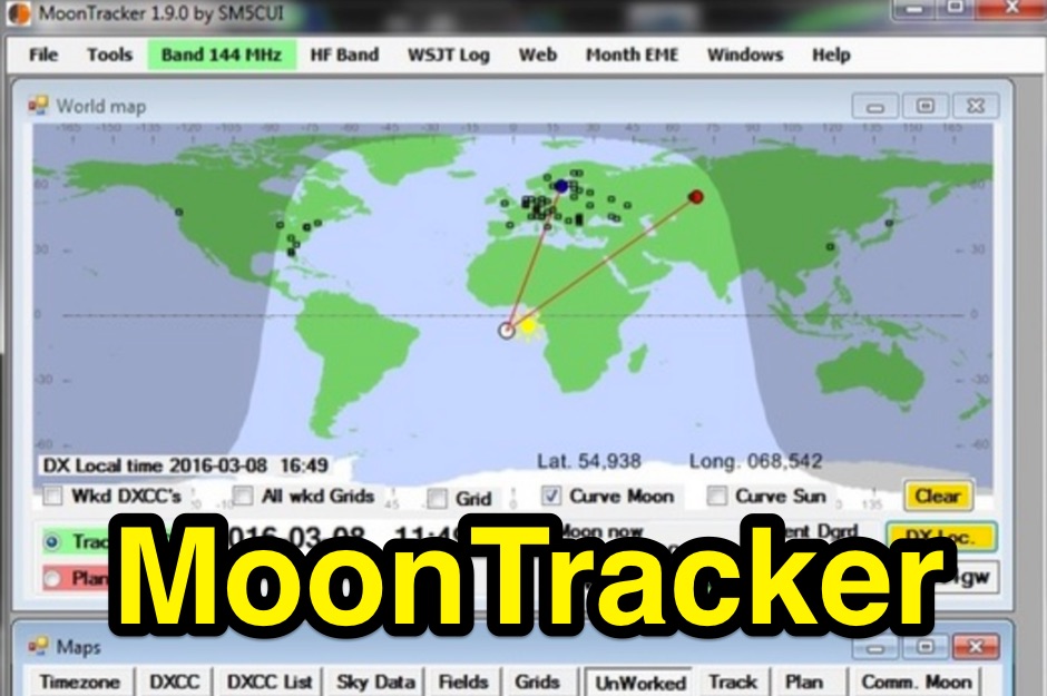 A moon tracking software capable to drive the rotation of your antennas in azimuth and elevation
 -

-
 A Wire resonant loop antenna for 160 meters band article by N4KC
 -
 An Unorthodox Antenna, originally by W3AWH is considered a multi-band antenna suitable for fixed location use and as an easily deployable portable antenna for events such as Field Days.
 -
 This resource details the four primary functions of a ground system: lightning energy dispersion, equipment safety, RF return path provision for end-fed antennas, and management of induced RF currents. It clarifies that a ground system's effectiveness varies depending on its specific function, noting that a good lightning ground might not be an effective RF ground. The content emphasizes that proper antenna system design, including baluns and appropriate feedline lengths, often negates the need for an RF station ground to mitigate common mode currents or RFI in the shack. The article quantifies lightning energy, stating its peak is in the dozens or hundreds of kilohertz, with damaging energy extending to hundreds of megahertz, and currents reaching thousands of amperes. It recommends solid, wide, smooth copper surfaces for ground leads to achieve low impedance across a wide frequency range. The author, W8JI, shares practical insights from his station, which includes two 300-ft towers and four 130-ft wire verticals, detailing his use of common point grounds and _DX Engineering RR-8 HD_ antenna switches for lightning protection without coaxial surge protectors. Specific examples of antenna systems prone to common mode current problems are listed, such as random wire antennas without proper feedline lengths and off-center fed dipoles. The text also explains how a ground screen or radial system can reduce local noise sensitivity for vertically polarized antennas by covering the lossy earth.
 -
 Decoding NOAA APT weather satellite images is achieved with a homebrew receiver and a Turnstile Cross Dipole antenna, feeding data to a Pentium-3 500MHz PC running Windows XP and the WXTOIMG program. This setup, operated by VU2IIA in Mumbai, India, focuses on capturing and processing signals from NOAA satellites to generate visual weather data. The blog documents the technical aspects of constructing the receiving station, including antenna design and receiver integration. It provides insights into the practical challenges and successes of amateur satellite reception, specifically for Automatic Picture Transmission (APT) signals. Operational details cover the software configuration and image processing workflow necessary to transform raw satellite data into usable weather imagery. The content serves as a practical guide for radio amateurs interested in satellite meteorology.
 -
 The resource, initially identified as "Alabama Radio," a dealer of amateur radios, antennas, CB equipment, scanners, and power supplies in Eastern Alabama, now redirects to a domain brokerage service. The original intent was to provide a commercial outlet for Ham Radio operators and CB enthusiasts seeking new equipment and accessories. This would have included transceivers, antenna systems, and various station components. However, the current content at the URL is _Startup Domains_, a platform for buying and selling premium .COM domain names. This shift means the resource no longer serves the amateur radio community directly. Instead, it focuses on digital asset transactions, with no mention of radio equipment, _DXing_, or _contesting_ activities. The original description of a regional radio dealer is no longer applicable to the live content.
 -
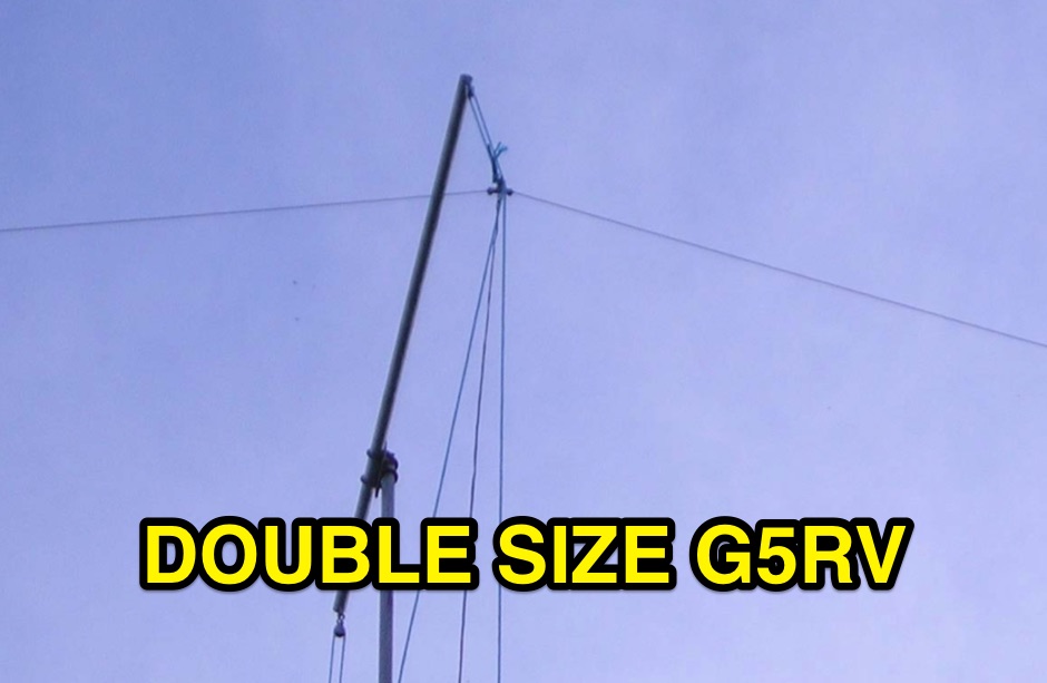 Building the double size G5RV antenna, part list, assembly part, dimensions and assembly instruction in a pdf document
 -
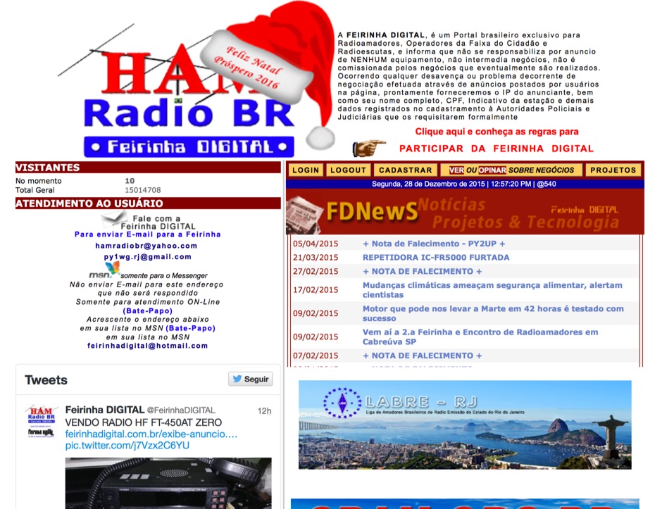 Presents a Brazilian online portal dedicated to **amateur radio**, **CB radio**, and shortwave listening (SWL) communities. The platform facilitates free classified advertisements for radio equipment, including HF, VHF, and UHF transceivers, antennas, and accessories. It also aggregates a substantial collection of technical articles from Brazilian amateur radio operators (e.g., PY2DJW, PY1LJ, PY1LL/4LC), covering topics such as CW training with RufzXP, balun importance, and radio wave characteristics. Furthermore, the resource provides extensive links to Brazilian ham radio sites, clubs, international organizations, and official ANATEL (Brazilian National Telecommunications Agency) documents regarding licensing, equipment homologation, and regulations. The portal features sections for user evaluations of transactions, a "Top Ten" list of most visited pages, and a calendar of past and upcoming ham radio events across Brazil, including "Feirinhas" (local swap meets) and "Encontros de Radioamadores" (hamfests). It also includes a directory of ham radio related businesses and services in Brazil, such as antenna manufacturers (Diex), QSL card printers (Arte Final), and repair technicians (PY2MOK). The site also offers propagation maps, DX cluster links (e.g., DX-SUMMIT), and satellite tracking tools, making it a central hub for Brazilian radio amateurs seeking to buy, sell, learn, or connect with the community.
 -
 This PDF document details the construction of a **70 MHz** Big Wheel antenna, a horizontally polarized omnidirectional array. The design utilizes three full-wave loops, each approximately **2160 mm** in diameter, arranged in a triangular configuration. The resource provides mechanical dimensions for the antenna elements and a comprehensive bill of materials, specifying component quantities and types, such as M8 stainless steel bolts, 15x15x1.5 mm square aluminum tubing for spacers, and 8 mm aluminum rod for the arcs. The central hub is constructed from two 160x160x8 mm aluminum plates, with four 40 mm long polyamide insulators supporting the radiating elements. The feed system incorporates a 50 mm diameter aluminum pipe for mounting and a matching stub constructed from a 120x20x2 mm aluminum sheet, connected via M8x10 mm bolts. The resource includes a diagram illustrating the mechanical dimensions and assembly points, including the N-connector fixing point and the center conductor attachment. The project was published on May 25, 2011, by Peter OE5MPL and Rudi OE5VRL. DXZone Focus: PDF | 70 MHz Big Wheel | Mechanical Dimensions | **2160 mm** loop diameter
 -
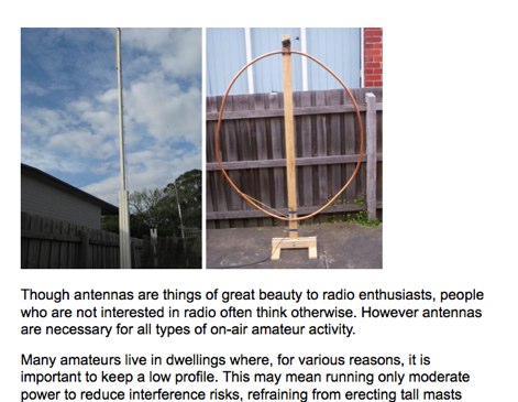 Antennas for restricted lots, apartments and indoor antennas by VK3YE
 -
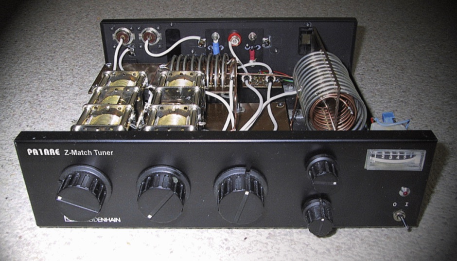 Most people are not familiar with antenna tuners and what a antenna tuner actually does.
 -
 Dodgy plans to make Archimedean spiral antenna for RTLSDR software defined radio receiver. Made of two equal lengths of coaxial cable seems to be the easiest circularly polarized antenna to make that will cover a broad range of the rtlsdr dongles E4000 tuners
 -
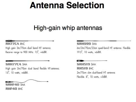 The document titled 'Extending the Range of Your Handheld' by WG7S is a guide on how to extend the range of your handheld VHF UHF transceiver by using an external antenna. It provides information on comparing popular models, selecting the right antenna, and resources for amateur radio antennas.
 -
 The 10-minute, 25-second video demonstrates making a QSO via the VO-52 amateur radio satellite, focusing on real-time Doppler shift correction. It features Simon, 2E0HTS, operating a Yaesu FT-847 transceiver and a homebrew dual-band Yagi antenna, specifically a 10-element 435 MHz Yagi for uplink and an IO Loop for 145 MHz downlink. The video visually details the operator's technique for continuously adjusting the uplink frequency to compensate for the satellite's changing velocity relative to the ground station, a critical aspect of successful satellite communication. The demonstration highlights the practical application of Doppler compensation, showing the operator tuning the transmit frequency to maintain a stable received signal from the satellite. This approach contrasts with systems employing automatic Doppler correction or full-duplex operation, providing insight into manual frequency management for satellite passes. The video serves as a direct, observational guide for hams interested in LEO satellite operations, particularly those using non-tracking, manually tuned setups.
 -
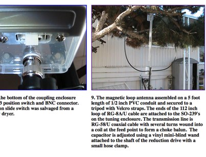 Here is a well documented plan of a 20m-10m compact magnetic loop antenna. Article includes lots of pictures and technical details published by KP4MD
 -
 80 to 6 meters, 2 KW, designed to be used at heights of only 25 to 45 feet, includes a twenty foot long vertical radiator
 -

-
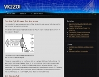 The Double 5/8 is a natural extension of the Single 5/8 and uses a 5/8λ element for both the top and bottom radiators.
 -
 Homebrew project of a windom antenna, an off center fed dipole, resonating from 10 to 80 meters
 -
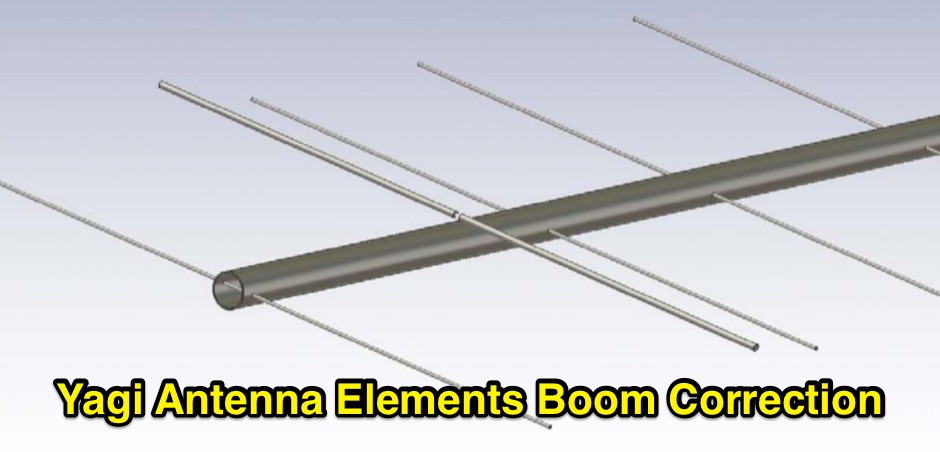 Dragoslav Dobricic, YU1AW antennex article on influence of Boom on frequency performance and how compensate it
 -
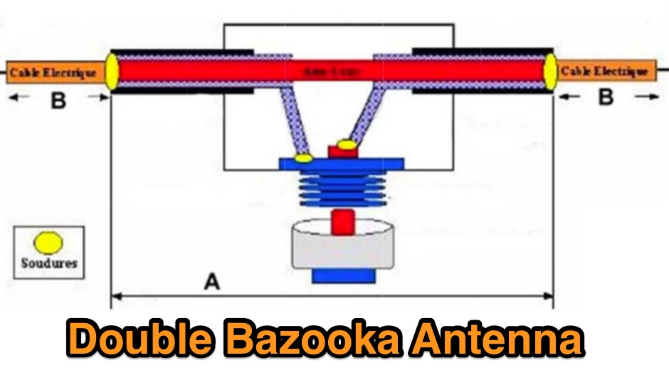
 The Double Bazooka Dipole is a very efficient single band antenna which is very quite,and does not require the use of a balun. This antenna consists of coax (RG58) with the shield split at the center and the feedline attached to the open ends.
 -
 The ZS6BKW multi-band antenna, an optimized variant of the classic G5RV, is presented with detailed construction and tuning instructions. This resource outlines the antenna's design principles, which were developed by _Brian Austin (G0GSF)_ using computer programs and Smith charts to achieve optimal dimensions. It provides specific guidance on calculating and adjusting the lengths of the radiators (L1) and the matching ladder line (L2), emphasizing the critical role of velocity factor (VF) in achieving resonance. The article includes a step-by-step procedure for empirically determining the VF of ladder line using an antenna analyzer, ensuring accurate physical lengths for the matching section. It details the tuning process for the radiators, offering practical tips for incremental adjustments to achieve the best SWR curve. The resource presents SWR measurement results obtained with an _AIM-4170C_ analyzer across multiple bands, alongside predicted SWR graphs from an AutoEZ model. It confirms successful contacts on 80, 40, 20, and 17 meters, including a **17-meter DX contact** to Italy. EZNEC and AutoEZ models for the ZS6BKW antenna, covering 80 through 6 meters, are provided for download, allowing further analysis and customization. The document specifies component details, such as the use of Wireman 554 ladder line and #14 AWG THHN copper wire, and discusses the antenna's performance characteristics, noting high SWR on 15 and 30 meters but successful tuning on 6 and 80 meters with an external tuner.
 -
 Windows Magnetic Loop antenna design software by DG0KW in Detusch
 -
 A K9AY loop antenna project done with Far Circuits pc boards for the antenna switch and bandpass filter and preamp by K7SFN
 -
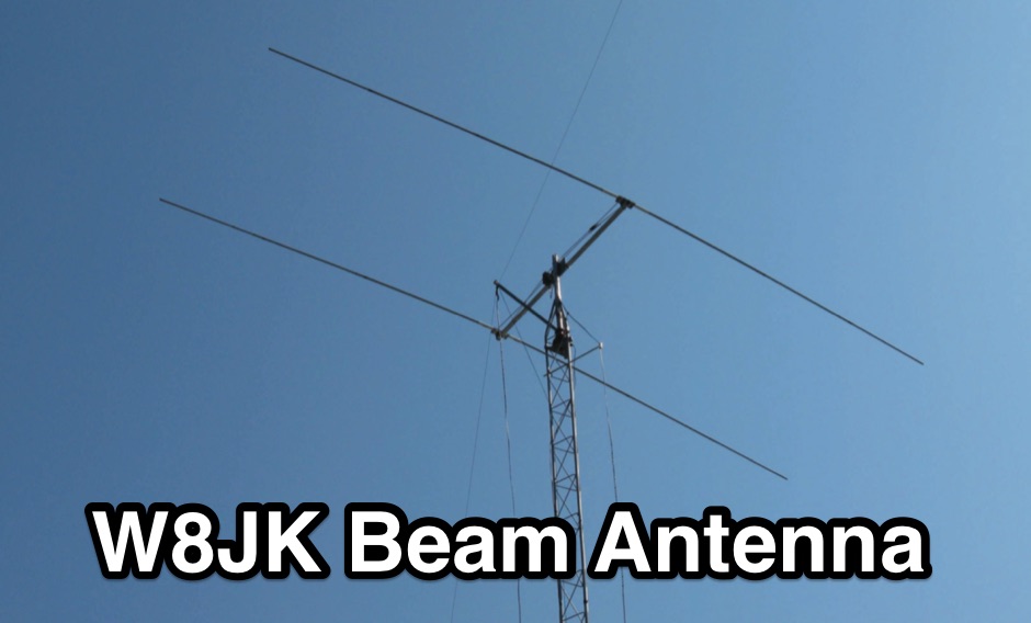 A Compact and efficient multiband beam antenna based on a Modified W8JK Array by K5LJ
 -
 Manufacturing distributor of infrastructure products for the telecommunications industry; antenna mounts, ice bridge, cable ladder, ground bars, weatherproofing, exothermic, safety equipment.
 -
 The GM4JJJ VHF and EME pages document David's extensive work in Earth-Moon-Earth (EME) communication, specifically on the 144 MHz band, and his involvement in amateur radio astronomy. The resource details his station setup and operational experiences, providing insights into the technical challenges and rewards of bouncing signals off the moon. It offers a glimpse into the specialized equipment and techniques required for successful EME contacts, a niche but highly rewarding aspect of amateur radio. David's content shares practical applications and field results from his EME endeavors, which can be particularly useful for hams contemplating or actively pursuing moonbounce operations. The information, while not a step-by-step guide, implicitly compares the complexities of EME with more conventional VHF/UHF operations, highlighting the significant power and antenna gain necessary to overcome path losses. This resource serves as a testament to the advanced capabilities achievable in amateur radio.
 -
 This project produces a sturdy tripod for small vertical antenna support using readily available electrical metal tubing (EMT) or conduit
 -
 The collinear J-Pole, often known as the Super-J, does improve the behavior over a regular J-Pole. As many attest, there is an advantage when vertically combining 1/2 radiating sections to have a bit of separation between the half-wave end points. The Super-J has very little separation between the two half-wave radiators.
 -
 Examines the historical role of telegraphy within Canadian railway operations, detailing the evolution of communication systems crucial for train dispatch and coordination. It covers the technical substance of railway telegraphy, including equipment, operational procedures, and the personnel involved, such as agents and operators. The resource provides insights into the **F59PH locomotive** history, development, and components, alongside diagrams of various parts like antennae and traction motors. The content also explores the practical application of these systems by documenting specific railway events, such as the CPR Galt Sub operations from 1895-1971 and GO Transit's operational history. It includes photo galleries, schematics, and diagrams of locomotives and cab cars, offering a visual and technical comparison of different railway equipment. The site also features information on **GO Transit** rolling stock, including MP40s and commuter coaches, providing a historical context for railway communication and transportation.
 -
 The TiltPlate is an antenna tilting mechanism that works with a tilt over tower and yagi to bring the antenna all the way down to ground level.
 -
 In this experiment the autor is going to explore the use of a 1:64 matching network on the End Fed Long Wire Antenna. Experiment will consist in build a 80-40-20-15-10 meter End Fed Long Wire Antenna with a 1:64 matching network from the documentation available on the internet
 -
 A system designed to automatically tune small transmitting magnetic loop antennas, particularly beneficial for **contest operations** where rapid frequency changes are common. The core of the system involves a PC-based control application, AutoCap, written in C#, which monitors antenna SWR via an external meter and commands a motor interface to adjust the loop's variable capacitor. The software is compatible with Windows and Linux via the Mono framework, offering a graphical user interface for monitoring system status, SWR, power, and motor commands. Key components include one or more magnetic loop antennas equipped with DC or stepper motors for capacitor adjustment, an SWR meter with data output (such as the Telepost LP-100A or a homebrew serial/USB SWR meter), the AutoCap PC software, and a motor interface. The most effective motor interface utilizes an **Arduino-based controller** with custom firmware, providing precise control over both simple DC motors and stepper motors, and supporting features like motor braking for finer adjustments. The system allows for configurable SWR thresholds, pulse widths, and motor effort settings to optimize tuning speed and resolution. Optional radio integration provides frequency hints, enabling the algorithm to learn the relationship between motor actions and resonant frequency, thereby speeding up initial tuning responses. The software also supports antenna profiles, allowing operators to save and recall specific configurations for different loops, including accumulated frequency hint data.
 -
 The HF horizontal loop has been around for many years now. This article includes a YouTube video and discusses the reasons for looking at this antenna, its design, and its installation. There are some on-air comparisons against three regular double bazooka (coax) dipoles and the Par SWL End-Fed antenna.
 -
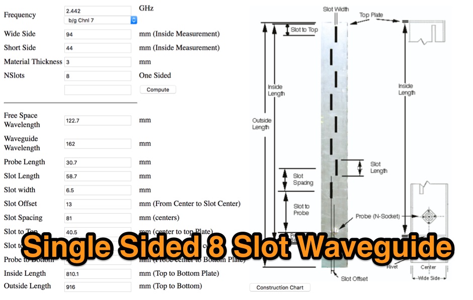 Online calculator and a full documented pictorial guide to build a single sided 8 slot waveguide antenna
 -
 Designing and constructing portable wire antennas for HF operations, this resource explores several configurations including the _foldback dipole_ for space-constrained setups and an inductively shortened dual-band dipole for 20m and 40m. It details the calculation of inductance for shortened elements, providing a Visual Basic 6.0 program screenshot that illustrates determining coil parameters like turns and length for a **25.5 uH** inductor. The document emphasizes practical considerations such as adjusting wire lengths for optimal SWR, noting that a dual-band dipole achieved SWR below 2:1 on both 20m and 40m, with careful adjustment bringing it under 1.5:1. Further, the resource describes a half-wave antenna matched with a coaxial stub, a method often referred to as the _Fuchskreis_ in German amateur radio circles, to transform the high feedpoint impedance to 50 Ohms. This monoband solution, for a 20m application, uses a stub length of **2.98m** (0.216 lambda multiplied by coax velocity factor) and a shorted stub of approximately 48cm. The coaxial stub design is highlighted for its resilience to ground proximity, allowing it to be rolled up or laid on the ground with minimal SWR impact, making it highly suitable for portable QRP operations.