Search results
Query: google.com
Links: 860 | Categories: 0
-
 A 2m Moxon antenna project, designed for the 145 MHz amateur radio band, provides a compact, directional solution for VHF communications. This resource details the construction process, specifying materials like PVC pipe for the frame, copper wire for elements, and a SO-239 connector for the feedpoint. The design emphasizes ease of build for hams seeking a gain antenna with good front-to-back ratio for local ragchewing or contesting. The project outlines precise element lengths and spacing, crucial for achieving the desired impedance and radiation pattern. It includes a visual representation of the antenna's dimensions and assembly, allowing for straightforward replication. The Moxon's inherent characteristics offer a practical alternative to larger Yagi arrays, particularly for portable operations or restricted spaces, while still delivering effective directivity and gain.
 -

-
 This program demodulates the telemetry data signal transmitted by the AO-40 satellite (aka Phase III-D) using the PC sound card
 -
-
 A 500-watt mobile antenna project details the conversion of an old 10m hamstick into a highly efficient, multiband "bugstick" for HF operation. The core modification involves replacing the original coil with 25 turns of 6 turns-per-inch, 1.5-inch diameter coil stock, fabricated from #14 wire. This design, intended for a 3-magnet mount on a vehicle cab, achieves resonance on multiple bands by shorting out specific turns on the coil, similar to a **bugcatcher** antenna. Measurements taken with an MFJ-259 analyzer on a GMC pickup show 0 turns shorted for 20 meters (14.2 MHz), 10 turns for 17 meters, 16 turns for 15 meters, 19 turns for 12 meters, and 23 turns for 10 meters. The construction emphasizes using UV-resistant tie-wraps and #14 solid wire with crimp lugs for robust RF connections, bypassing the fiberglass rod for current flow. A bonus section details a 40-meter version, utilizing 48 turns of 8 TPI, 2-inch diameter coil stock.
 -
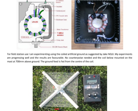 A vertical antenna that can cover HF bands using an UN UN and a fishing pole, usage of tuner is requested.
 -
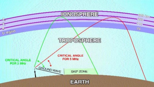 This article will help to unravel some of the mysteries as well as giving useful operating tips to maximize your chances of working that rare station
 -
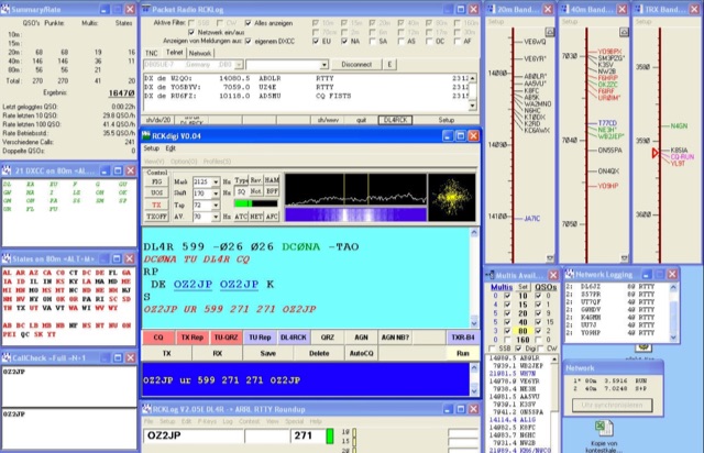 RCKLog is a windows freeware program for logging and administration of SSB and CW-Contest with simultaneous control of transceiver and real-time operation of Packet-Radio.
 -
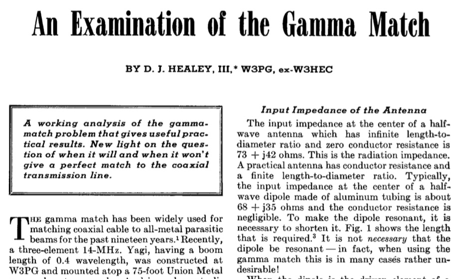 A Working analysis of the gamma match problem that gives useful practical results in a article dated April 1969.
 -
 An Off-center-feed antenna that covers 80, 40, 20, 17, 15, 12, 10, and 6 meters
 -
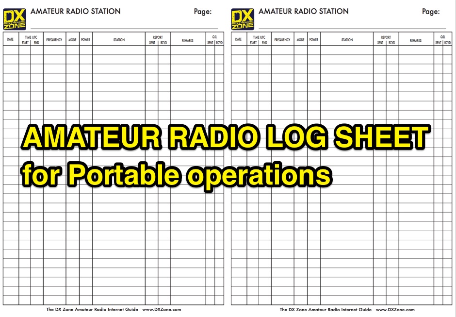 A free to download and print, paper log sheet useful for portable amateur radio operations, in a PDF file.
 -
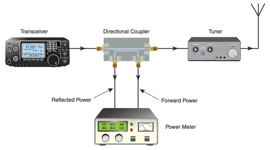 Every ham needs an RF power meter. Here is a high performance unit to build at home.
 -
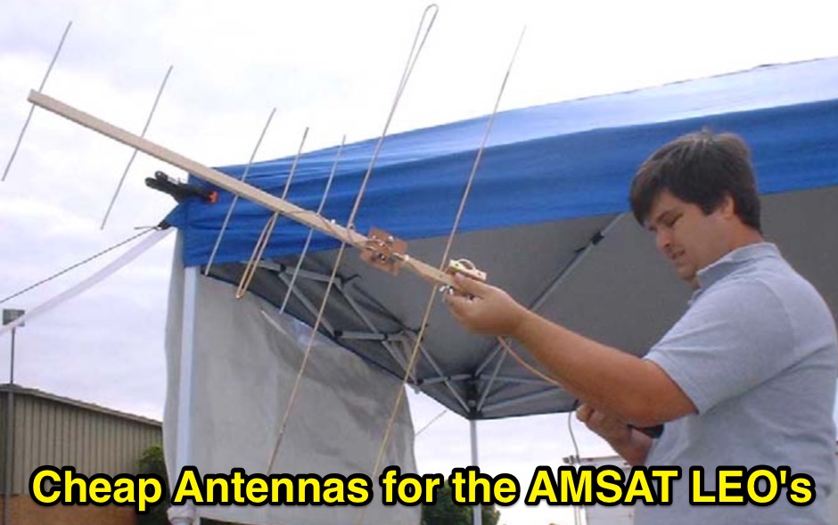 Cheap Antennas for the AMSAT LEO Kent Britain WA5VJB
 -
 How to operate on 10 and 20 meters in limited space with this trapped dipole.
 -
 Notes on Axial-Mode Helical Antennas in Amateur Service. Helix Basics, Modeling Issues, and Short Helical Antennas Over Perfect Ground
 -
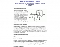 Design guidelines for Op Amp audio preamplifier circuits by Mike Martell N1HFX
 -
 A DIY project details the construction of a modular QRP CW transceiver specifically designed for the **20-meter band**. The design is segmented into three distinct modules—VFO, Receiver, and Transmitter—allowing for phased construction and independent testing. The VFO circuit, capable of operating as a conversion VFO or a free oscillator, provides a frequency span of approximately _70 KHz_ (2.433 to 2.510 MHz) with a 4V pp output level, utilizing a Colpitts FET oscillator and buffer. The receiver employs a classic superheterodyne architecture with MOSFETs in the front end and mixer for improved overload immunity, incorporating a 4-crystal ladder filter with a 600 Hz bandpass and an LM386 audio power amplifier delivering about 1W into an 8-ohm load. The transmitter section uses frequency conversion with an NE602 mixer to achieve 14 MHz operation, featuring a power broadband stage capable of 4-5W output into a dummy load, and includes a double Pi filter for signal cleanliness. The resource provides detailed component lists, tuning instructions for each module, and 1:1 scale PCB layouts for single-sided boards.
 -
 Transistor and its history and lot of related infos
 -
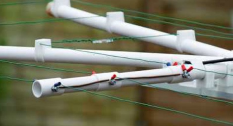 A PDF presentation of a home made moxon antenna for 50 MHz 70 MHz and 144 Mhz. The project is mainly out of surplus plastic Plumbing pipes and clips etc, and also details of how the dimensions were calculated.
 -
 N1HFX article on adjustable voltage regulator
 -
 This document details the design and construction of a Vinecom 6N4 dual-band Yagi antenna for the 50MHz (6-meter) and 70MHz (4-meter) amateur radio bands. The antenna features 9 total elements (4 elements for 50MHz, 5 elements for 70MHz) on a 4.236-meter aluminum boom. Computer simulations using MMANA software predict 7.21 dBd gain on both bands with front-to-back ratios of 16.01dB (6m) and 15.37dB (4m). The design uses 12.7mm diameter elements mounted on a 32mm square boom, weighing 5.7kg total. Practical measurements with an MFJ-269 analyzer confirmed good SWR performance across both bands after element length adjustments.
 -
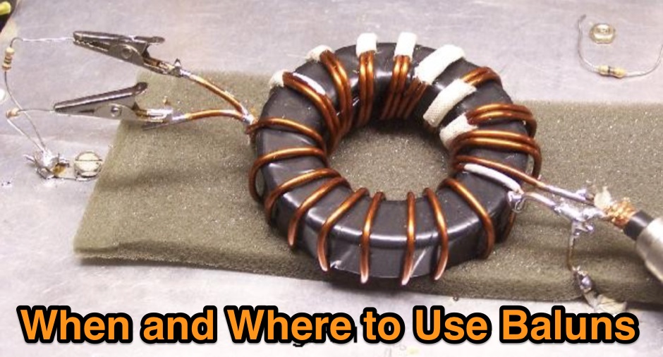 The document provides a comprehensive overview of baluns, which are devices used to connect balanced loads, like dipole antennas, to unbalanced inputs, such as coaxial cables. It covers various types of baluns, including voltage and current baluns, and their design, construction, and testing. The text discusses the importance of baluns in preventing RF currents on coax shields and their applications in Ham radio setups. It also includes practical advice on selecting and using baluns based on antenna impedance and power ratings, along with detailed performance evaluations and construction tips for different balun configurations.
 -

-
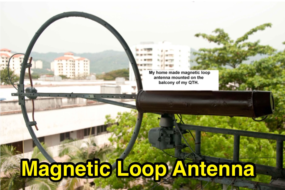 If you have space constraint at your QTH for a HF antenna, you can try contructing this HF magnetic loop antenna for 40-20 meters bands
 -
 A bowtie antenna is a type of antenna that reputedly provides higher gain at lower radiation angles than a center-fed dipole antenna at heights considerably less than 1/2 wavelength above ground.
 -
 This is a design for a stealthy HF multi-band vertical wire antenna using a tree as a supportby G7AQK
 -
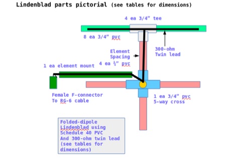 This document contains the detailed instructions to build a homemade lindenblad antenna using a twin-lead as dipole elements. This document contains 9 pages and includes a detailed construction sequence and some drawings to build this antenna for UHF and VHF ham radio bands
 -
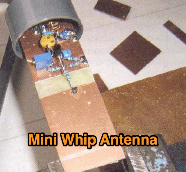 An active receiving antenna for 10 KHz to 20 MHz, a very small sized antenna with excellent performances in noise to signal ratio.
 -
 Homebrew a compact yagi antenna for 14 Mhz suitable for those with small plots based on a design by AB4GX
 -
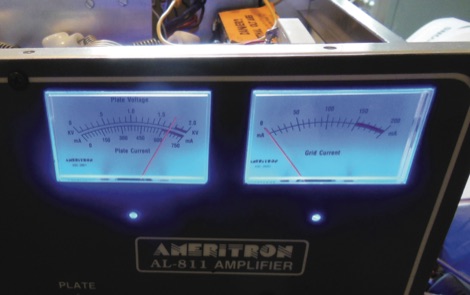 A solutiom for the Ameritron AL-811(H) RF power amplifier, burnt panel meter lights. A common failure with the Ameritron AL-811 and similar amplifiers is that the panel meter lights burn out prematurely. These bulbs are usually integrated into the actual panel meter. The solution for this is to provide the meter backlighting with LEDs.
 -
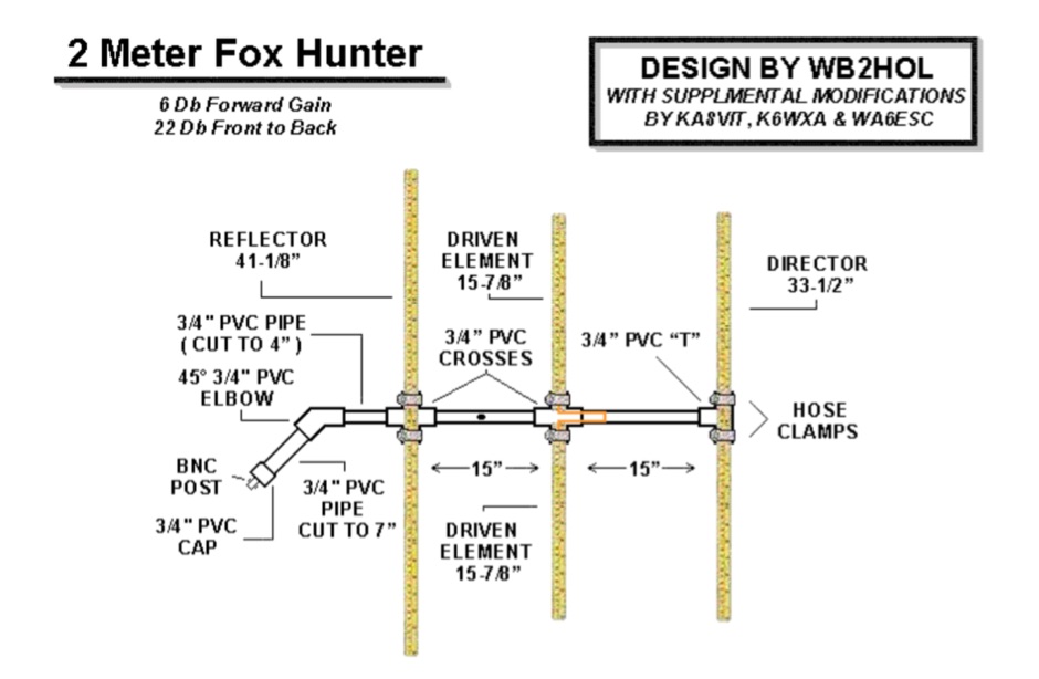 A home made yagi antenna featuring 6db forward gain and 22 Db front back
 -
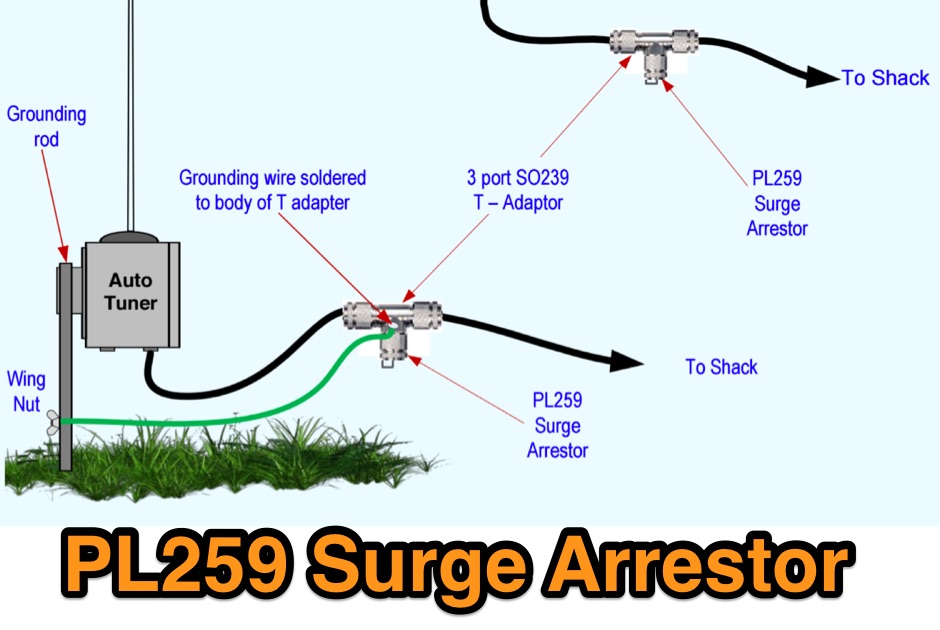 A sourge arrestor for PL 259 connectors. A voltage surge arrestor to limit the voltage that may come back down the wire or coax after there has been static build up
 -
 The GW3YDX Super Moxon antenna design improves upon the standard Moxon Rectangle by incorporating additional directors in a rectangular configuration, yielding enhanced directivity and gain. For the 6m version, modeling with 4NEC2 and EZNEC+ indicated a 3dB gain increase and a 26.5dB front-to-back ratio, with VSWR below 1.5:1 between 50.0 and 50.3MHz when optimized for 50.1MHz. This design achieves a narrower -3dB power point beamwidth of 60° compared to the original Moxon's 80°, contributing to better QRM rejection. The boom length for the enhanced design is just under 2m, approximately double the original Moxon's, with no increase in wingspan. Construction details include tubing lengths for 6m, 4m, and 2m versions, with specific dimensions provided for elements A through M, measured to tubing centers. For instance, the 6m version uses a 2160mm element A and a 2140mm element H. The design maintains a 50-ohm feed impedance, with practical models showing VSWR plots consistent with simulations after minor adjustments to driven element lengths. The article also references Moxgen software for initial Moxon parameter calculation and NEC/EZNEC model generation. The 2m Super Moxon version measures approximately 30" x 25", demonstrating the compact nature of the design across different VHF bands. The article highlights the antenna's performance in real-world DX contacts on 6m, achieving contacts with over 80 stations in the USA from a modest QTH.
 -
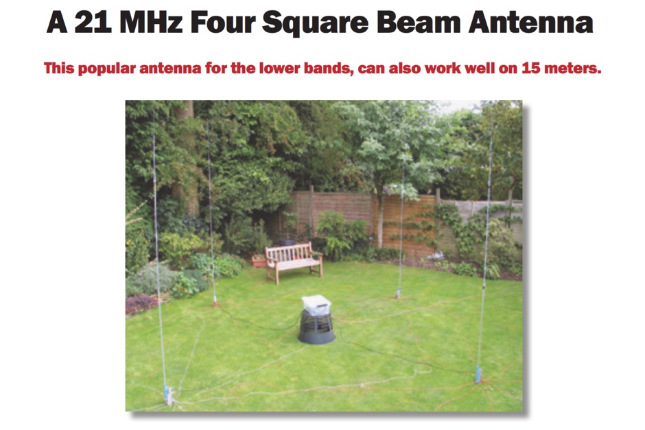 A 21 MHz Four Square Beam Antenna This popular antenna for the lower bands, can also work well on 15 meters, QST Article
 -
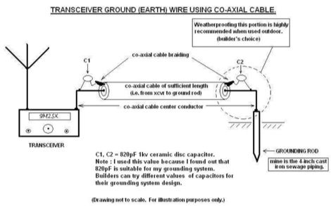 Improper grounding or earthing system can cause several unwanted RF interferences (RFI) to television sets, broadcast receivers, hi-fi sets and telephone sets. In this Article the author explain how to setup a proper radio shack grounding using coaxial cable and ceramic disc capacitor
 -
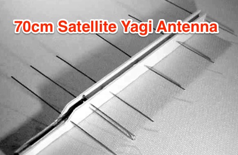
-
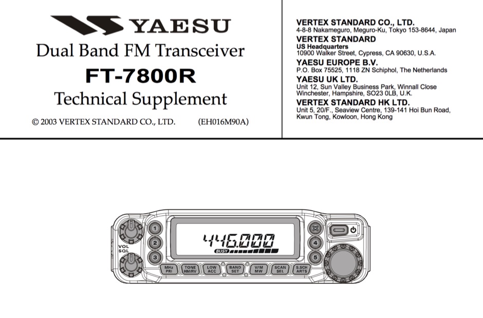 Service manual in PDF Format for the Yaesu FT-7800 transceiver
 -
 VHF UHF diplexer by G8MNY
 -
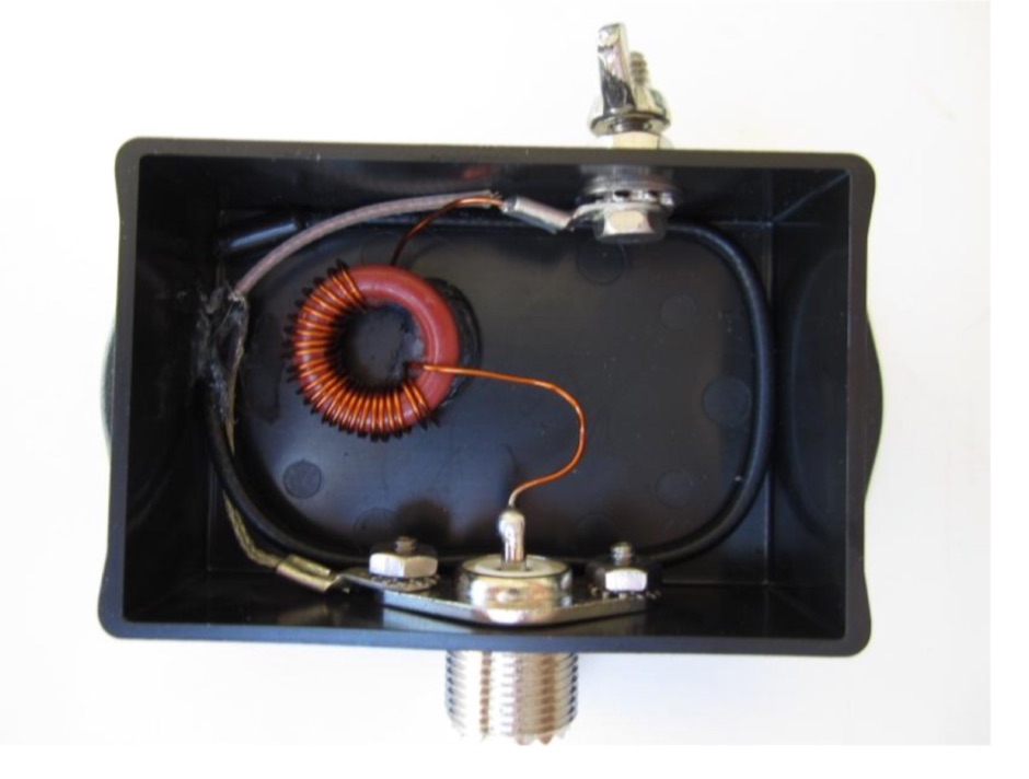 An end fed 20 meter half wave antenna
 -
 Presents the construction of a 6-meter (50 MHz) Moxon wire beam antenna, detailing the use of #14 AWG THNN stranded wire and a treated wood frame. It covers the assembly of a galvanized pipe mast, emphasizing the use of pipe sleeves for joint reinforcement over threaded couplers to prevent breakage during raising and lowering operations. The resource also describes the integration of a 1:1 current balun, rated for 50-54 MHz, and the use of RG-8X coax for the transmission line, recommending low-loss alternatives like Belden 9913-7F. Further, it outlines a manual rotation mechanism using pipe hanger clamps and carriage bolts for true North orientation, incorporating magnetic declination calculations from NOAA. The antenna's performance is discussed, noting good gain and take-off angle, with SWR tuning facilitated by a Palstar AT-500 manual tuner. An EZNEC+ 5.054 model for the antenna is available for download, alongside predicted radiation patterns and SWR curves, compared with actual AIM-4170C measurements.
 -
 Key your transmitter from the tone output of a Morse Code generator program
 -
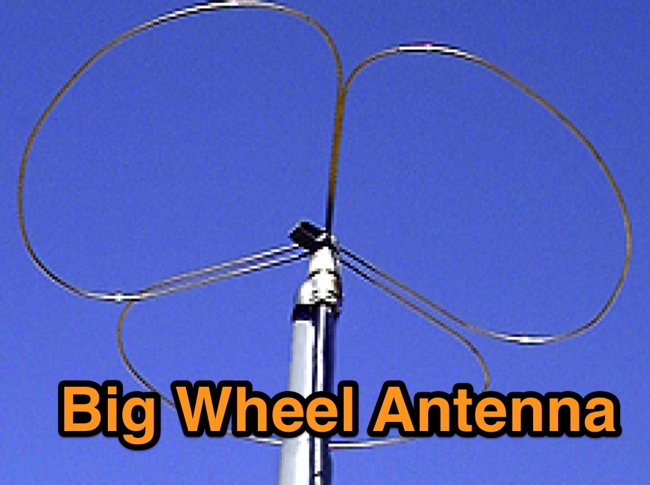 A Useful Horizontally Polarised Omni-directional Antenna with Gain for 144 MHz
 -

-

-
 A PDF presentation about Amateur Radio and Linux by By: Dave Mamanakis. A beginners guide to Linux for radio amateurs, this presentation cover basic concepts of the open source operative system, from the basic installation to the setup of ham radio programs.
 -
 Part 2 You're now much closer to saying goodbye to your unwanted signal problems!
 -
 A compact antenna for 160 meters, suitable for hams tha want operate top band buh have a limited space
 -
 W3EDP antenna assembly instructions and dimensions with pictures in this PDF File
 -
 An home made vertical dipole antenna made with simple material. The antenna has a total length of aproximately 16 feet. In this article appeared on June QST 2019, the author explain how he reached the optimal confirugation changing and adjusting the lower part of the antenna, trimming and spacing correctly the copper wire. PDF File to downloas
 -
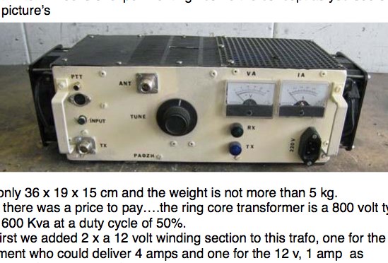 2 x GI7B in push-pull 2m and 6m 1kW Power amplifier from PA0ZH