Search results
Query: 2 meter
Links: 683 | Categories: 46
This query is too generic. Please try adding an additional term to focus your research.
Categories
- DX Resources > Beacons > 10 meter beacons
- Antennas > 20M > 20 meter Dipole Antennas
- Antennas > 20M > 20 meter Vertical Antennas
- Antennas > 20M > 20 meter Yagi antennas
- Antennas > 40M > 40 meter Dipole Antennas
- Antennas > 40M > 40 meter Loop Antennas
- Antennas > 40M > 40 meter Magnetic Loop Antennas
- Antennas > 40M > 40 meter Vertical Antennas
- Antennas > 6M > 6 meter J-Pole Antenna
- Antennas > 6M > 6 meter Yagi Antennas
- Technical Reference > Test Equipment > Multimeter
- Manufacturers > Test Equipment > Multimeters
- Manufacturers > Test Equipment > Power Meter
- Technical Reference > Power Meter
- Manufacturers > SWR Meters
- Technical Reference > SWR Meters
- Manufacturers > Wattmeters
- Antennas > 40M > 40 meter Delta Loop Antennas
- Antennas > 40M > 40 meter Yagi Antennas
- Antennas > 6M > 6 meter Moxon Antennas
- DX Resources > Beacons > 6 meters beacons
- Antennas > 10M
- Antennas > 12M
- Antennas > 15M
- Antennas > 17M
- Antennas > 20M
- Antennas > 2M
- Antennas > 30M
- Antennas > 40M
- Antennas > 60M
-
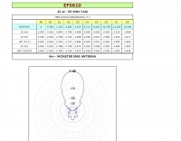 This is a plan for a 10 elements yagi antenna for 50 mhz
 -
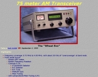 Frequency coverage: 3.75 MHz to 4.00 MH transceiver for 75 MHz band
 -
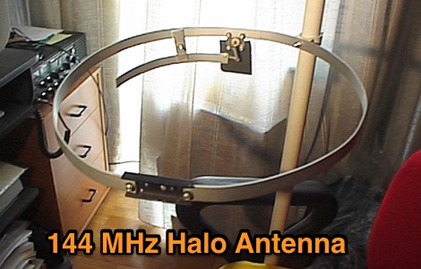 Italian web site describing a project for a 2 meters home made halo antenna
 -
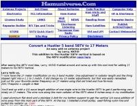 Convert a Hustler 5 band 5BTV to 17 Meters An easy add on antenna project by Larry, KK5ID
 -
 40/20/10 Meter Fan Dipole attic antenna article by KD2GOE
 -
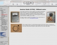 Meter capable of accurately measuring low levels of RF power
 -
 Durable Easy To Build 4 Element 6 Meter Quad Or 6N2 Or 4 Element 6 And 5 Element 2 Permanent Or Portable you decide based on your needs By WA8UEG
 -

-
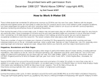 The webpage provides guidance on working 6 Meter DX, focusing on effective operating habits, preparation, and knowledge of the band. It emphasizes the importance of monitoring, clear frequencies, and using CW for weak signals. It also mentions the significance of knowing countries and individual stations on the air to increase chances of working DX. The page recommends utilizing resources like newsletters and websites to stay updated on 6-meter activity and offers suggestions for improving operating skills.
 -
 An homemade fan dipole antenna for 20 30 40 meter bands, setup in a 15 meter wide garden. The longest leg for 40 meter is folded to fit in the 7.5 m
 -
 SWR Graphing Software for Amateur Radio by KD4UDY, shareware
 -
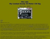 PRC-38S Combat Ready 30 Meter CW Rig Steve Yates - AA5TB
 -
-
 Demonstrates the construction and implementation of a **two-element phased vertical array** for 40 meters, utilizing _Christman phasing_ techniques. The author, W4NFR, details the process from building individual 1/4-wave aluminum verticals to integrating them into a phased system. The resource covers antenna spacing of 32 feet, elevated radial design, and the critical steps for tuning each vertical to achieve a 1.1:1 SWR before combining them. It also provides insights into calculating precise coax lengths for feedlines and the phasing delay line, emphasizing the use of an MFJ-269 Antenna Analyzer for verification. The finished system exhibits good front-to-back nulls, with an overall SWR ranging from 1.6:1 to 2.2:1, which is managed by an antenna tuner. The project includes detailed photos of the relay box, showing 12 VDC relays capable of handling 5KV, and the control box in the shack for switching between three different antenna pattern configurations. Static bleed-off chokes are incorporated for protection, and the construction emphasizes robust weatherproofing for outdoor elements.
 -
 A project of a small antenna, just 50 cm for the 7 MHz band. An EH Antenna plan for the 40 meters band
 -
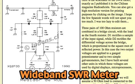
 When building antennas for the Wifi band , a need for an easy way to check the antennas arise. This is a project for a 2.4 GHz band SWR Meter
 -
 This project details the construction of a **full-sized 40-meter vertical antenna**, born from a renewed interest in 7 MHz operation and a desire for improved effectiveness over simple dipoles. The author, K5DKZ, initially focused on VHF experimentation, which provided an inventory of aluminum tubing and fiberglass spreaders for this endeavor. Before this vertical, K5DKZ utilized an 80/40 meter inverted-vee trap dipole and a 40-meter broadband dipole, but now primarily uses a pair of full-sized, phased, quarter-wave verticals spaced 35 feet apart for serious 40-meter work. The construction involves a base-heavy design for stability, using a 44.5-inch section of 1-1/4 inch steel TV mast driven into 1-3/8 inch aluminum tubing, insulated by a 105-inch section of Schedule 40 PVC pipe. The assembly reaches 31 feet, close to the 32 feet required for a quarter-wavelength on 40 meters, with fine-tuning achieved by winding wire onto a fiberglass spreader. The design is explicitly presented as a foundation for a two-element 40-meter Yagi beam, outlining modifications like substituting aluminum for steel in the base and using an inductive hairpin match for the driven element. The article also discusses tuning considerations for a large 40-meter beam, noting the 100 to 200 kHz upward frequency shift when raised, and suggesting methods for installation on a tower. The author emphasizes the cost-effectiveness and good performance of the monopole approach, especially when multiple verticals are needed.
 -
 Lights on why 160 meters is so unpredictable and what is being done to reveal its secrets
 -
 A 2 element small footprint 40 meter phased, reversible, downsized quad array antenna.
 -
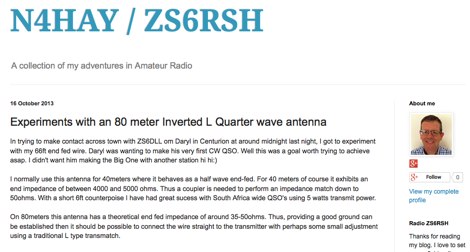 Experiments with an 80 meter Inverted L Quarter wave antenna
 -
 Green that aluminum into something useful right in your own backyard by WB2CQM
 -

-
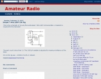 This is the schematic of asolid-state 7 MHz QRP CW transmitter by VU2NAN
 -
 Operating on the 11-meter band, the Alfa Tango Argentina website serves as a digital hub for CB radio DX enthusiasts, particularly those affiliated with the _Alfa Tango_ international group. The resource primarily functions as a community portal, facilitating connections among members and promoting activities related to long-distance CB communications. It presents basic information about the group's presence in Argentina and emphasizes the social aspect of radio communication, framing participants as "friends who have never met." The site's content reflects the operational focus on **DXing** within the CB radio sphere, a practice that mirrors amateur radio's pursuit of distant contacts. While specific operational data or technical guides are not detailed, the site's existence supports the organizational structure of the Alfa Tango group, which coordinates activities across various countries.
 -
 A moxon antenna project made with wires and fiberglass poles
 -
 Design and build an 6 m dipole antenna from aluminum, tubing, that resembles the active element of a yagi beam antenna.
 -
 An home made magnetic loop antenna project using a military surplus 150pf capacitor by KF5CZO
 -

-
 An homebrew project for a 3 element coil-loaded Yagi beam antenna for 40 Meter band
 -
 The 80m TX described here is the well known ON7YD ATX-80 and timer, combined and re-engineered to fit a readily available enclosure by G3ZOI
 -
 Demonstrates the adaptation and construction of a 7-element DK7ZB Yagi antenna for the 4-meter band (70 MHz), utilizing components from a defunct 2-meter CUE DEE Yagi. The resource details the modifications made to the original DK7ZB design to fit the shorter CUE DEE boom length, specifically adjusting element lengths for 6mm rod elements while reusing existing mounting holes for the reflector and last director. It provides precise element lengths for the reflector, dipole (12mm aluminum tube), and five directors, along with a note on cutting elements for transport. The article includes a 4NEC2 simulation file for performance analysis and an SWR plot, confirming the antenna's electrical characteristics. It also specifies the calculation for the quarter-wavelength matching cable using SAT752F coaxial cable, resulting in a 909mm length. Practical application is shown with the finished antenna in operation at JO20XC, listing several activated Maidenhead squares such as JO56PA and JP40KS, validating its effectiveness for portable 70 MHz operations.
 -
 This PDF document details the construction of a **70 MHz** Big Wheel antenna, a horizontally polarized omnidirectional array. The design utilizes three full-wave loops, each approximately **2160 mm** in diameter, arranged in a triangular configuration. The resource provides mechanical dimensions for the antenna elements and a comprehensive bill of materials, specifying component quantities and types, such as M8 stainless steel bolts, 15x15x1.5 mm square aluminum tubing for spacers, and 8 mm aluminum rod for the arcs. The central hub is constructed from two 160x160x8 mm aluminum plates, with four 40 mm long polyamide insulators supporting the radiating elements. The feed system incorporates a 50 mm diameter aluminum pipe for mounting and a matching stub constructed from a 120x20x2 mm aluminum sheet, connected via M8x10 mm bolts. The resource includes a diagram illustrating the mechanical dimensions and assembly points, including the N-connector fixing point and the center conductor attachment. The project was published on May 25, 2011, by Peter OE5MPL and Rudi OE5VRL. DXZone Focus: PDF | 70 MHz Big Wheel | Mechanical Dimensions | **2160 mm** loop diameter
 -
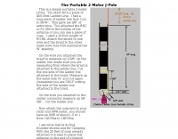 This is a simple portable 2-meter J-Pole antenna. You start with a piece of 450-Ohm Ladder Line
 -
 A simple low-power broadcast-type circuit, using a crystal oscillator integrated circuit and an a collector modulated AM oscillator
 -
 Homebrewed transceiver for 20 meter originally born for 17 meters band
 -
-
 Article describing how to homebrew a yagi antenna for 50 MHz, includes plans for a four and five elements yagi beam and details how how match impedence with a gamma match
 -
-
 A lightweight portable vertical antenna for 40m
 -
-
-
 80-meter peilontvanger / receiver includes printed circuit sample and list of components
 -
 A 144 Mhz Slim Jim Antenna, aluminum tubing version project by Mohammad 9W2WTF
 -
 A Co-ax Trap Dipole For 40, 30 and 20 Meters or at last that was the intention
 -
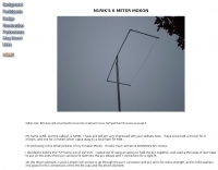
 6 Meter 1/4 Wave Antenna by Mike Fedler N6TWW. A detailed article with pictures of construction details of this 50 Mhz antenna
 -
 A simple antenna analyser for the HF spectrum with a built-in signal generator with 3-digit LED frequency display.
 -
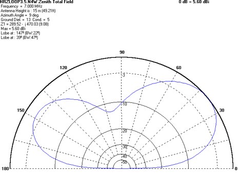
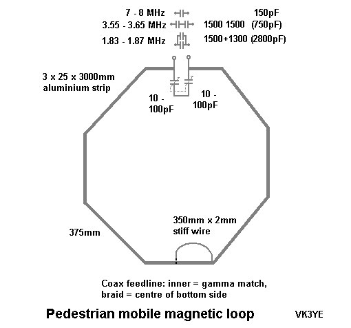 A magnetic loops for HF pedestrian mobile project by VK3YE
 -
 In this PDF article Zack Lau describe how to homebrew a four element yagi beam antenna for 50 MHz band, including how to build mounting blocks and tubing clamps to hold elements.
 -
 A project for a 50 MHz moxon rectangle antenna
 -
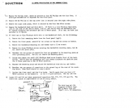 Dovetron modification for the Kenwood TL922A