Search results
Query: 4m antenna
Links: 82 | Categories: 1
Categories
-
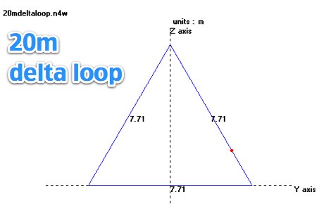 This antenna is fed for vertical polarisation, to give a low angle of radiation for DX and also a nearly omni-directional radiation pattern.
 -
 The QM7 antenna is a simple 7 elements Yagi with 3.7 m boom length for the lower 144 MHz SSB/MGM band, in PDF Format
 -
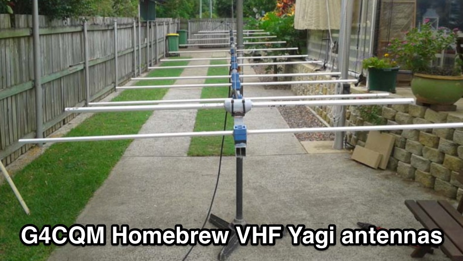 Homebrew VHF Yagi 50MHz 144MHz 432MHz 1296MHz 2320MHz 6M 2M 70CM 23CM 13CM Yagis
 -
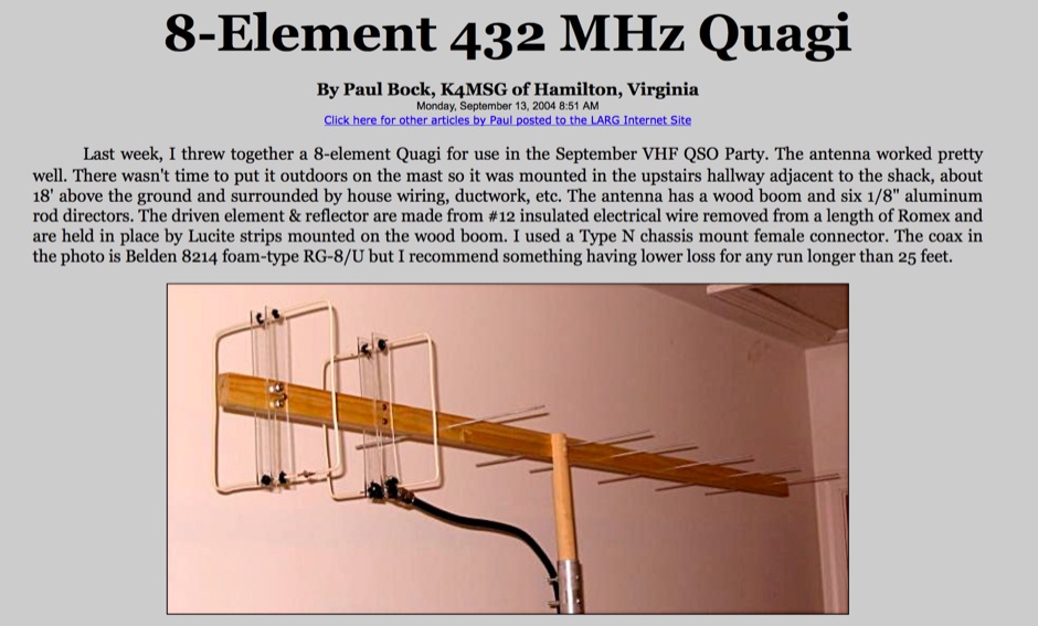 How to build a 432 Mhz Quagi, using a wood-made boom, and gives a 13 DBI Gain
 -
 Delta Loop Antenna for 15m band. This antenna is made for operating from outdoors, mainly from mobile shack. Drive to a parking you like, then build it up. Just half an hour later, you can enjoy slightly better gain than normal dipole.
 -
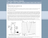 This project details three variants of a vertical half-wave antenna design for the 4-meter (70MHz) amateur radio band. The antennas use end-feeding with a parallel-tuned circuit for impedance matching to 50-ohm coaxial cable. The first variant uses suspended flexible wire for portable use, the second employs a fiberglass rod with internal wire for permanent outdoor installation, and the third utilizes aluminum tent poles for quick mobile deployment. Despite the narrow bandwidth of the matching circuit, this suits the narrow 4m FM allocation well. The design offers an effective omnidirectional radiation pattern and can be constructed with readily available materials.
 -
 Demonstrates the construction and performance of an updated ZS6BKW multiband dipole, a variant of the _G5RV_ antenna, specifically designed for HF operation. The article details a real-world installation using 13.5m copper wire elements and 12.2m of 450 Ohm ladder line, configured as a sloping inverted-V with the apex at 10m and ends at 4m above ground. It covers the critical aspect of impedance matching, incorporating an 8-turn choke balun at the feedline transition to RG-58U coax to mitigate RF common mode current. Measurements confirm favorable SWR readings below **1.3:1** on 7.1 MHz, 14.11 MHz, 18.06 MHz, and 24.8 MHz, indicating effective resonance across 40m, 20m, 17m, and 12m bands. The installation also shows usable SWR dips on 3.55 MHz (5:1), 29.02 MHz (2:1), and 50.84 MHz (3:1), extending its utility to 80m, 10m, and 6m with an antenna tuning unit. Initial on-air results report clear reception of stations over **5000km** away, validating its DX potential.
 -
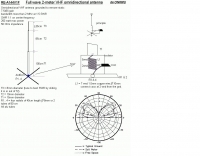 A full wave 2-meter VHF omnidirectional antenna by ON6MU
 -
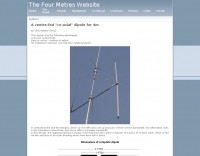 Easy to setup dipole antenna for 4 meters band by Tony Hawker G4CJZ
 -
 Inverted vee dipole antenna for 20 meters band by VK1OD
 -
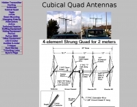 A project by N6BG for a four element cubical quad antenna for the 2 meters band
 -
 20 meter wire j-pole for 14.2 MHz, a vertical, end-fed half wave antenna by N1LO
 -
 A homebrew project for a 2 meter 4 element yagi beam antenna by 2E0HTS
 -
-
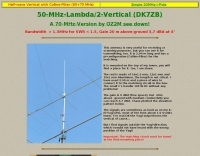 This antenna is very useful for receiving or scanning purposes, but you can use it for transmitting, too. It is 2,94m long and has a pi-configuration (Collins-Filter) for the matching.
 -
-
 The article "Exploring the World of 10 Meter Beacons" by Ken Reitz, KS4ZR, provides an in-depth look at 10-meter beacon operations, focusing on their utility for propagation analysis. It details FCC Rules part 97.203 governing beacon stations, including license requirements, power limits (under 100 watts), and the specified band segment of 28.200-28.300 MHz for U.S. operations. The content highlights the diversity in beacon construction, from converted CB radios to home-brew QRP transmitters, and discusses the robust operating conditions these 24/7 stations endure. The resource presents several case studies of active 10-meter beacon operators like Ron Anderson KA0PSE/B, Domenic Bianco KC9GNK/B, and Bill Hays WJ5O/B, detailing their equipment, antenna setups, and typical signal report volumes. It also introduces the NCDXF/IARU International Beacon Project, which features 18 synchronized beacons worldwide transmitting on 28.200 MHz at varying power levels (100W, 10W, 1W, 100mW) to facilitate propagation testing. The article also covers the PropNet Project utilizing PSK31 on 28.131 MHz and the 250 Synchronized Propagation Beacon Project on 28.250 MHz. Practical advice for monitoring includes using the RST reporting method, understanding the impact of the solar cycle on 10-meter propagation, and tips for setting up a personal beacon, such as frequency selection and power output considerations. The IY4M Guglielmo Marconi Memorial Beacon Robot on 28.195 MHz is also mentioned for its automatic QSO mode. The article concludes with a list of other resources for 10-meter beacon information.
 -
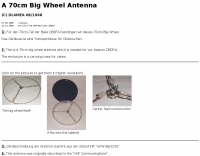 This is a 70cm big wheel antenna which is used at DB0FAI beacon
 -
 An homebrewed dipole antenna for 14MHz
 -
 Constructing a Lindenblad antenna for 137MHz NOAA satellite reception involves specific design considerations for optimal performance. The resource details the use of 4mm galvanised steel fencing wire, 300-ohm television ribbon cable, and wood/plastic components for the antenna structure. Key dimensions for a 137.58MHz-resonant antenna are provided, derived from the ARRL Satellite Handbook, specifying s, l, w, and d as 42, 926, 893, and 654mm respectively. The antenna is designed for Right Hand Circularly Polarised (RHCP) signals, requiring the four folded dipole elements to be tilted clockwise by 30 degrees. A significant aspect covered is impedance matching between the antenna's 75-ohm impedance and a typical 50-ohm receiver input. A twelfth-wave matching transformer, constructed from 117mm sections of 50-ohm RG-58 and 75-ohm RG-59 coax with a 0.66 velocity factor, is described. The article also addresses coaxial cable and connector selection, recommending 75-ohm Type-N connectors for RG-6 cable in professional setups and F56/F59 connectors for general use, while strongly advising against PL-259/SO-259 connectors for VHF. Strategies for mitigating Radio Frequency Interference (RFI) are discussed, including antenna placement to shield from local TV transmitters and the use of commercial or DIY band-pass filters, such as cavity resonators or helical notch filters, along with ferrite chokes on coaxial cables. Antenna orientation is explored, noting the Lindenblad's 'cone of silence' directly overhead and its maximized sensitivity towards the horizon. An experimental vertical tilt of 90 degrees is presented as a method to improve overhead reception and reduce interference from strong horizontal signals, particularly relevant in high RFI environments like the Siding Spring Observatory site.
 -
 Constructing a high-gain, compact antenna for 2 meters often involves balancing theoretical performance with practical build challenges. WB8AHT recounts his journey in building a 6-element _Super Duper Moxon_ antenna for 144 MHz, inspired by designs from M0PXS and GW3YDX. He initially encountered discrepancies in published dimensions for the _HAARP Antenna_ and the _Super Moxon_, leading to on-air SWR issues and suboptimal performance. His methodical approach involved cross-referencing, direct communication with Phil Simpson (M0PXS), and iterative adjustments to element lengths based on observed results and a _SARK-110 Antenna Analyzer_ scan. After modifying the reflector/driven element and third director dimensions, the antenna achieved a respectable 1.35:1 SWR at 144.200 MHz. Field testing with 50 watts yielded contacts up to 500 miles, suggesting performance close to the 15 dBi gain predicted by _4NEC2_ software, despite its compact 40-inch boom. The article includes specific construction notes, such as tubing sizes (1/2-inch and 3/8-inch aluminum) and feedpoint spacing (50mm). The author's experience highlights the importance of real-world validation for antenna designs, even those with strong theoretical backing. He provides a table of tubing lengths for 6m, 4m, and 2m versions, along with his final, optimized dimensions, offering a practical blueprint for fellow hams interested in replicating or further experimenting with this high-performance, small-footprint VHF antenna.
 -
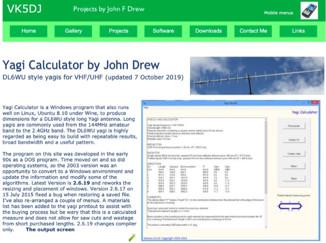 Yagi Calculator is a free Windows program that also runs well on Linux, Ubuntu 8.10 under Wine, to produce dimensions for a DL6WU style long Yagi antenna. Long yagis are commonly used from the 144MHz amateur band to the 2.4GHz band.
 -
 This article describes the 144MHz horizontally polarised antenna at VK1OD in November 2008. The antenna uses two identical four element arrays that were constructed around 1970
 -
 The ZS6BKW antenna, a popular multiband wire antenna, offers improved band matching compared to the traditional G5RV. This construction guide details the process, beginning with specific dimensions: 13.11 meters (43 feet) for the 450-ohm ladder line and initial dipole arm lengths of approximately 14.8 meters each. It emphasizes the critical role of an _antenna analyzer_ for accurate tuning, particularly for determining the velocity factor of the ladder line and achieving a 1:1 impedance match. The article outlines the materials required, including a 1:1 current balun, 450-ohm window line, wire for the dipole arms, and a 50-ohm non-inductive resistor for testing. It provides a step-by-step procedure for cutting the ladder line to its electrical half-wavelength, explaining how to calculate the velocity factor using measured and free-space frequencies. For instance, a measured 50-ohm impedance at 12.54 MHz with a calculated free-space half-wavelength frequency of 11.44 MHz yields a velocity factor of 0.91. Final adjustments involve hoisting the antenna to its operational height and fine-tuning the dipole arm lengths to achieve optimal SWR, specifically targeting 14.200 MHz. The _ZS6BKW_ design is noted for its performance on 80m, 40m, 20m, 10m, and 6m, though it is not optimized for 15m operation. The author, _VK4MDX_, shares practical tips for durable construction using stainless steel wire and cable clamps.
 -
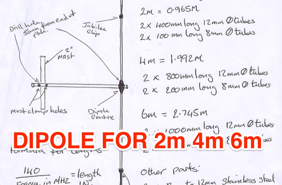 A dipole for 2m, 4m, 6m band an hamdwritten note for a homemade vhf antenna that can be tuned across the VHF band
 -
 A 2m Moxon antenna project, designed for the 145 MHz amateur radio band, provides a compact, directional solution for VHF communications. This resource details the construction process, specifying materials like PVC pipe for the frame, copper wire for elements, and a SO-239 connector for the feedpoint. The design emphasizes ease of build for hams seeking a gain antenna with good front-to-back ratio for local ragchewing or contesting. The project outlines precise element lengths and spacing, crucial for achieving the desired impedance and radiation pattern. It includes a visual representation of the antenna's dimensions and assembly, allowing for straightforward replication. The Moxon's inherent characteristics offer a practical alternative to larger Yagi arrays, particularly for portable operations or restricted spaces, while still delivering effective directivity and gain.
 -

-
 This QRZ.com callbook entry by DL6GD details the construction and performance of a **40m/80m Morgain folded dipole antenna**. The resource includes a schematic diagram, construction photos, and tuning notes. The antenna, with a total length of **20.30m**, was mounted at a height varying from 4m to 6m above ground. Construction utilizes 0.75 sq mm transparent insulated copper wire, with Plexiglas spreaders (5mm thick, 70x10mm) spaced at 25mm intervals, secured with hot glue. A waterproof junction box houses the feedpoint and balun. Tuning involved adjusting wire bridges for resonance on each band. On 80m, an SWR of **1.1:1** was achieved at 3.657 MHz, with an SWR of 2.7:1 at 3.580 MHz and 2.5:1 at 3.755 MHz, yielding a bandwidth of 175 KHz. For 40m, an SWR of **1.1:1** was measured at 7.100 MHz, with 1.5:1 at 7.000 MHz and 1.3:1 at 7.200 MHz, providing a 200 KHz bandwidth. DL6GD notes that 80m tuning exhibits slight height sensitivity, while 40m tuning is less affected by height or 80m adjustments. Long-term observations from 2014 and 2022 document SWR degradation due to environmental factors like spiderwebs and ice accumulation, which can cause HF-conductive paths between elements. DXZone Focus: Callbook Entry | 40m/80m Morgain Dipole | SWR Measurements | 20.30m Length
 -
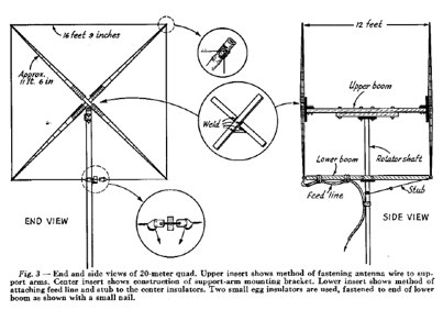 January 1955 QST article by W5DQV about constructing a Cubical Quad antenna for 14MHz PDF File
 -
 This 4m Slim Jim Antenna is cheap and easy to build yet it greatly out performs the more usual dipole due to its low angle of radiation. An SWR of 1:1 is obtainable across the 4m ham radio FM band with a simple adjustment.
 -
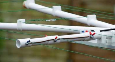 A PDF presentation of a home made moxon antenna for 50 MHz 70 MHz and 144 Mhz. The project is mainly out of surplus plastic Plumbing pipes and clips etc, and also details of how the dimensions were calculated.
 -
 This document details the design and construction of a Vinecom 6N4 dual-band Yagi antenna for the 50MHz (6-meter) and 70MHz (4-meter) amateur radio bands. The antenna features 9 total elements (4 elements for 50MHz, 5 elements for 70MHz) on a 4.236-meter aluminum boom. Computer simulations using MMANA software predict 7.21 dBd gain on both bands with front-to-back ratios of 16.01dB (6m) and 15.37dB (4m). The design uses 12.7mm diameter elements mounted on a 32mm square boom, weighing 5.7kg total. Practical measurements with an MFJ-269 analyzer confirmed good SWR performance across both bands after element length adjustments.
 -
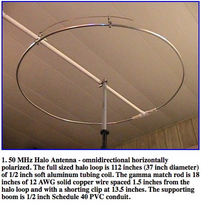 A well documented article about construction and analysis of a horizontally polarized halo antenna for 6 meters band by Dr. Carol F. Milazzo, KP4MD
 -
 The GW3YDX Super Moxon antenna design improves upon the standard Moxon Rectangle by incorporating additional directors in a rectangular configuration, yielding enhanced directivity and gain. For the 6m version, modeling with 4NEC2 and EZNEC+ indicated a 3dB gain increase and a 26.5dB front-to-back ratio, with VSWR below 1.5:1 between 50.0 and 50.3MHz when optimized for 50.1MHz. This design achieves a narrower -3dB power point beamwidth of 60° compared to the original Moxon's 80°, contributing to better QRM rejection. The boom length for the enhanced design is just under 2m, approximately double the original Moxon's, with no increase in wingspan. Construction details include tubing lengths for 6m, 4m, and 2m versions, with specific dimensions provided for elements A through M, measured to tubing centers. For instance, the 6m version uses a 2160mm element A and a 2140mm element H. The design maintains a 50-ohm feed impedance, with practical models showing VSWR plots consistent with simulations after minor adjustments to driven element lengths. The article also references Moxgen software for initial Moxon parameter calculation and NEC/EZNEC model generation. The 2m Super Moxon version measures approximately 30" x 25", demonstrating the compact nature of the design across different VHF bands. The article highlights the antenna's performance in real-world DX contacts on 6m, achieving contacts with over 80 stations in the USA from a modest QTH.
 -
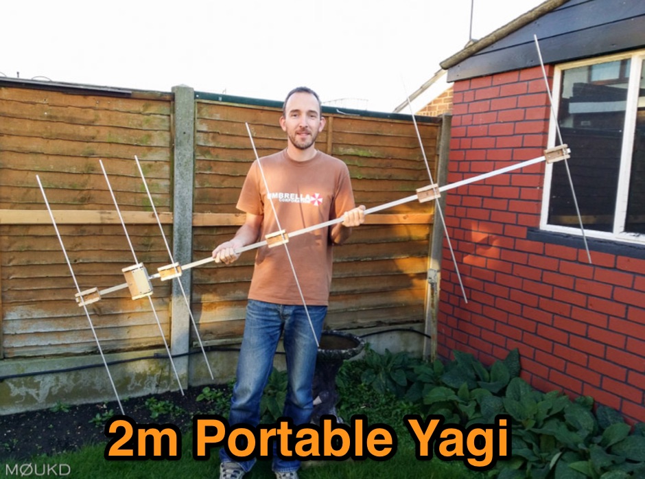 Building a 2 metre 144MHz VHF Yagi beam antenna, designed for portable use.
 -
 2 Meter Indoor Slim Jim Antennas for Cyclone Season and Other Uses by VK4MDX
 -
 This ia a home built Magnetic loop antenna which was used by G3BGR, indoors on 7,10 and 14Mhz. The basic idea was in Radcom 1986
 -
 Optimizing a G5RV or ZS6BKW multiband wire antenna for HF operation often involves addressing common SWR issues and understanding feedline characteristics. This resource chronicles the construction and performance evaluation of a G5RV, initially built for 80m, 40m, 15m, and 10m bands, by a newly licensed Foundation operator. The author details the selection of materials, including 3.5 mm stainless steel wire for the doublet arms and enameled copper wire for the open-wire feeder, and the initial decision to omit a balun based on common online information. The narrative highlights the initial disappointing performance, characterized by high receive noise and poor signal reports on 80 meters, despite the transceiver's internal ATU achieving a 1:1 match. This led to experimentation with a coax current balun and further research into G5RV myths, such as SWR claims and the necessity of a balun. The author then describes modifying the antenna to the ZS6BKW configuration, which involves specific changes to the doublet and feedline lengths, and integrating a 1:1 current balun wound on a ferrite toroid. The modifications resulted in improved reception and transmit performance across the bands.
 -
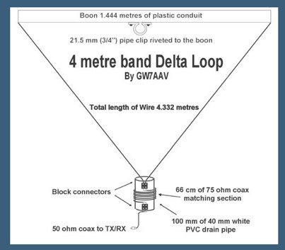
-
 A 2-meter Moxon beam antenna, designed for the _144 MHz_ band, is detailed, originating from a desire to participate in the PW 2m QRP contest. The design, based on a Moxon Rectangle, offers a compact directional solution for VHF portable operations. The author, G0KYA, constructed the antenna using readily available materials like 15mm plastic conduit for the frame and 1.5mm copper wire for the elements. Initial testing with an MFJ-259B antenna analyzer showed a **1.2:1 SWR** at 144.300 MHz, indicating good resonance. The antenna's compact size, approximately 70cm x 40cm, makes it highly suitable for portable QRP work, providing a significant advantage over an omnidirectional vertical. The project includes practical advice on element spacing and construction techniques, emphasizing ease of assembly for field deployment. Field results from a local hilltop demonstrated the Moxon's directional characteristics, allowing for effective nulling of local noise and improved signal reception from specific directions.
 -
 A 6 dB gain Moxon rectangle antenna, designed for the 2-meter band, offers an excellent solution for hams seeking a compact, directional antenna for **SSB** operation, particularly in restricted spaces like an attic. This design emphasizes ease of construction using readily available materials such as 4mm OD brass tubing and plywood, making it an accessible project for many radio amateurs. The antenna's inherent characteristics, including a high front-to-back ratio of 37 dB and a 50-ohm feed impedance, contribute to its effectiveness in mitigating local noise and focusing radiated power. The project leverages the free MoxGen program for precise dimension calculations based on the desired frequency and wire size, and utilizes 4nec2 for pattern analysis, confirming a 3 dB beamwidth of 80 degrees. Construction involves bending brass tubing for the driven and passive elements, mounting them on an 800 x 350 mm plywood boom, and securing them with cable clips and epoxy resin. Initial SWR measurements at 144.3 MHz showed 1.6:1, which improved to 1.3:1 at 145.3 MHz across a flat band from 144.1 MHz to 145.5 MHz after adding a **coaxial choke** to mitigate common mode current.
 -
 This Z-Match is a link coupled all-band tuner. Two all band tank circuits cover 3-14mhz and 14-30mhz. The tank output links are selected with a very heavy duty SPDT rotary switch.
 -
 This article compares two commercial vertical antennas for the 4-meter amateur radio band: the Watson WVB-70 half-wave and the Sirio CX4-71. The Watson measures 2.03m in length, costs around £40, and exhibited adequate performance but required additional waterproofing after rain affected its VSWR readings. The longer Sirio CX4-71 (3.02m) performed noticeably better, delivering signals approximately 2 S-points stronger than the Watson. The Sirio demonstrated high build quality, a stable 1.2-1.4:1 VSWR, and weather resilience, though minor VSWR fluctuations were observed during rain and frost. Both antennas are half-wave designs requiring no ground plane radials.
 -
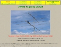
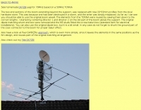 A 5 elements homemade DK7ZB yagi antenna for 4 meters band based on a 50MHz TONNA
 -
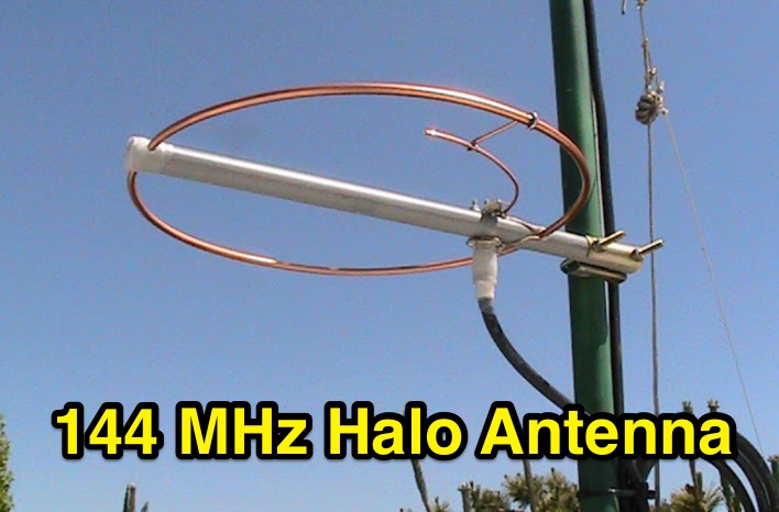 Construction and analysis of a low cost omnidirectional horizontally polarized antenna for 144 MHz, including notes on halo antenna stacking
 -
 A home made dipole antenna for 10m, 6m, 4m bands made with two sections of 450 and 300 Ohm ladder lines, cut to achieve acceptable SWRs on all bands
 -
-
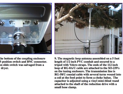 Here is a well documented plan of a 20m-10m compact magnetic loop antenna. Article includes lots of pictures and technical details published by KP4MD
 -
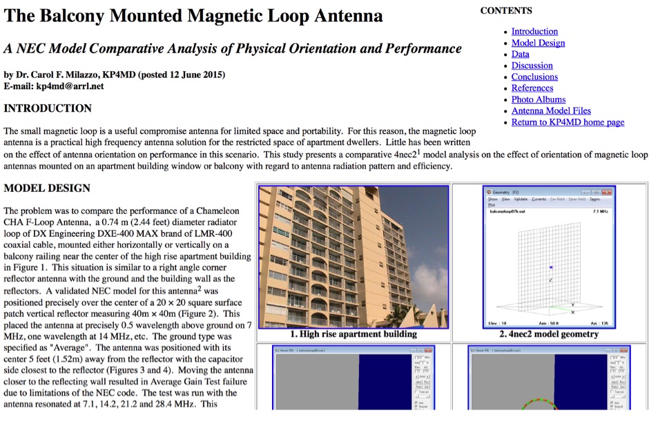 A NEC Model Comparative Analysis of Physical Orientation and Performance. The small magnetic loop is a useful compromise antenna for limited space and portability. For this reason, the magnetic loop antenna is a practical high frequency antenna solution for the restricted space of apartment dwellers
 -
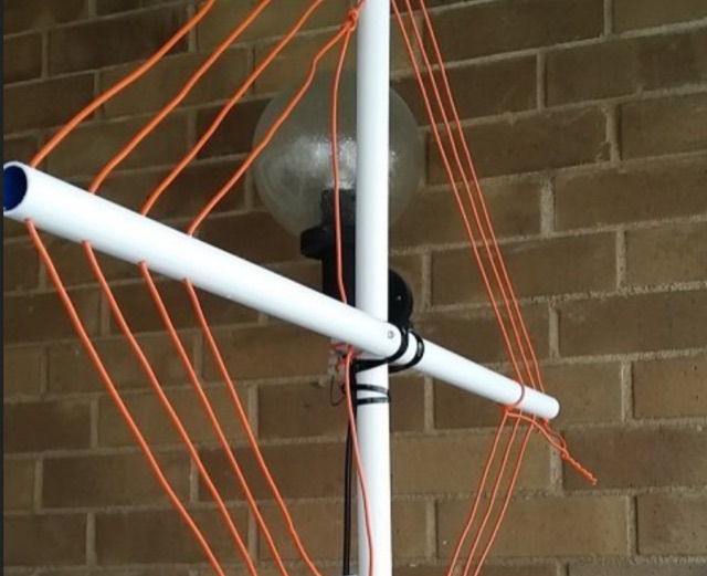 This antenna can gets you on the air on 14MHz, and it has a useable frequency range. The VSWR is almost perfect at the centre-frequency abd the design uses no expensive components.