Search results
Query: Resonance
Links: 87 | Categories: 0
-
 Dissects the internal components of the popular _Antron 99_ vertical antenna, revealing its unique design elements. The analysis details the construction of the coaxial phasing sections, which contribute to its multi-band performance across 10, 12, 15, and 17 meters. Observations include the use of fiberglass tubing for weather protection and the specific arrangement of conductors within the antenna's structure. The examination highlights the antenna's reliance on a series of coaxial stubs to achieve resonance on multiple HF bands without external tuning. This internal architecture provides insights into how the _Antron 99_ manages impedance matching and radiation patterns for effective DX operation. Further details cover the antenna's base mounting and overall physical dimensions.
 -
 The antenna is nothing more than a simple 2.4 metre square loop drawing pinned to the internal brick wall of the spare bedroom. Yep, thats right, the inside wall of the spare bedroom - ideal for flat dwellers, hotel rooms or whinging neighbours, The loop has a simple switched inductance at the top of the square loop and uses a simple coaxial stub to tune the antenna. An additional variable capacitor placed across the feedpoint can be used to fine tune the resonance of the antenna, by Andy G0FTD
 -
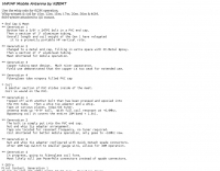
 The HB9ABX mobile HF antenna, developed by _Felix Meyer_, offers a high-performance alternative to commercial mobile antennas for 80 through 10 meters. Constructed from fiberglass rods and enamelled copper wire, this design incorporates a loading coil with multiple taps, allowing for band-specific tuning. The article provides detailed instructions for winding the coil, connecting the antenna elements, and integrating it with a vehicle's chassis ground. Field tests conducted at 100W consistently showed the HB9ABX antenna outperforming a HUSTLER mobile antenna by up to **10 dB** (1 S-point) and a YAESU ATAS-100/120 by **18 dB** (2-4 S-points) across distances from 5 km to 1000 km. The design emphasizes a robust ground connection and the use of an antenna tuner, such as an _MFJ-901B_, for optimal SWR on all bands, particularly 40 and 80 meters. Initial adjustment involves setting whip length and coil tap positions to achieve resonance without a tuner, followed by fine-tuning with the tuner during operation. Specific measurements are provided for checking resonance on 21.0 MHz and 14.2 MHz, with precise turn counts for the lower (79 turns) and upper (120 turns) antenna sections. Safety precautions for handling fiberglass dust are also highlighted.
 -
 HamCalc is a free collection of calculators for radio amateurs include Antenna ERP calculations, Attenuators, Audio Filter design, Coil Winding, Decibels, Great Circles map and calculator, HF Filters, HF Traps, Metric conversions OP Amps QRA Locator to Latitude/Longitude, Radio Horizon calculator, Resonance Satellite orbit calculator Timer calculations (555 timer)Zener Diode calculations Download zip By G4VWL
 -
 Simple wire antenna cheap to make, using readily available materials, Low angle radiation, with rejection of high angle signals Wide bandwidth, with resonance at the 80M DX window (3.790-3.800 MHz); and Maximum height is 40 feet
 -
 This is the antenna w3ff designed for his walking portable station. It is a dipole constructed out of the plastic plumbing pipe CPVC. There are telescoping whips at the ends of each side of the dipole, and these whips are adjusted to bring the antenna into resonance on each of five HF Bands 10, 12, 15, 17, and 20 Meters
 -
 A self-supporting vertical antenna design for stationary-mobile HF-VHF operation is presented, emphasizing ease of construction with common materials like a fiberglass fishing rod and PVC pipe. The design focuses on creating a set of no-tuner monoband radiators for bands such as **2m**, **6m**, 10m, and 12m, with an overall radiator support length of 3.3m. The construction process details the assembly of the antenna base using a magnetic mount, PL-259 connector, and PVC pipe sections, which then supports the telescopic fishing rod. Radiator extensions are cut to achieve quarter-wave resonance on specific bands, with detailed instructions for 6m (50-51 MHz), 10m (28.5 MHz), and 12m (24.9 MHz). For lower HF bands like 15m, 17m, and 20m, the design incorporates base-loading coils, with specific turn counts provided (e.g., 21 turns for 20m). The project also suggests using an _antenna analyzer_ for precise tuning of extensions and coils, moving beyond theoretical values to achieve optimal performance. The author, _IK1ZYW_, notes that for 80m and 160m, the antenna becomes less efficient as a vertical, suggesting alternative configurations like an inverted-V dipole or asymmetrical inverted-L.
 -
 Presents the KE4UYP linear-loaded vertical antenna design, which introduces very little loss on 80 or 160 meters, achieving an overall radiation efficiency of 80% to 85%. This design addresses common pitfalls of traditional base-fed verticals by placing the majority of the current at the top of the antenna, eliminating the heavy reliance on extensive ground radial systems. The author's initial 10-meter model, only three feet tall, yielded 5/9 signal reports to Anchorage, AK, and Europe, confirming its effectiveness. The antenna incorporates both vertically and horizontally polarized radiators, with a 1/4 wavelength horizontal counterpoise located at the feed-point, near the top, to create an almost totally omnidirectional pattern with high wave angle horizontally polarized radiation. This dual polarization ensures even illumination across all take-off angles, making it effective for both local contacts and **DXing**. The vertical element is linear loaded, adding capacitance reactance and making it longer than the horizontal element to achieve resonance and raise the feed-point impedance to 50 ohms. Fine-tuning the antenna requires careful adjustment, as tower reactance can vary. The article suggests starting with 80 feet for 80m and 170 feet for 160m for the vertical wire, then trimming for resonance. Bandwidth specifications include 300 kHz under 2:1 **SWR** on 80m and 100 kHz on 160m when suspended between trees, or 150 kHz on 80m when side-mounted on a tower.
 -
 The Flower Pot Antenna project details a portable dual-band antenna primarily operating on 10 meters, with secondary resonance near the 30-meter band. Construction involves winding RG58 coaxial cable uniformly around a large plastic flower pot, approximately 70cm high with a 60cm top diameter. The design eliminates the need for radials, contributing to its compact and lightweight nature. Key construction steps include soldering the inner conductor to the shield at one end of the wound cable and connecting the wound cable's shield to the rig cable's inner conductor at the base. An LC network, comprising a variable capacitor (0-200pF) and an inductor (10 coils, 5cm diameter, 2mm wire), is inserted between the wound cable's inner conductor and the rig cable's shield. Tuning is performed with an antenna analyzer, adjusting cable length and the variable capacitor for optimal impedance on 10 meters. The antenna performs effectively when installed horizontally.
 -
 Constructing a **reduced-size coaxial Moxon rectangle** antenna for the 17-meter band is detailed, presenting a method to achieve a compact directional antenna. The resource outlines the use of RG-58/U coaxial cable for elements, enabling a substantial reduction in physical dimensions compared to traditional wire or tubing Moxon designs. It provides specific instructions for tuning coaxial elements using an **MFJ-259B antenna analyzer**, including a formula to calculate trimming lengths based on measured resonance and desired frequency. The article explains how to prepare the coaxial cable for both driven and reflector elements, specifying connections for testing and final assembly. Performance data from an MFJ-259B shows SWR readings between 1.0 and 1.2 across 18.068 MHz to 18.168 MHz, with R values from 51 to 59 ohms and X values of 0 or 6 ohms. The antenna's power handling is approximately 500 watts continuous, limited by the RG-58/U coax. Comparative receive testing against an All-Band Sterba Curtain at 50 feet indicated a 2 S-unit reduction for the coaxial Moxon at 9 feet, suggesting optimal performance at a height of 34-40 feet for a 15-18 degree take-off angle. The design achieves an electrical quarter wavelength with over 30 percent size reduction.
 -
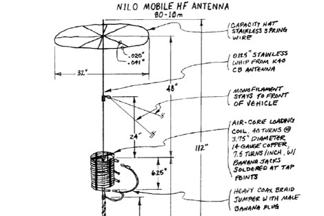 A **mobile HF multiband antenna** project details the construction of a center and top-loaded design, optimized for 10 through 80 meters. This antenna incorporates a capacity hat positioned high on the whip for enhanced efficiency, differing from commercial bugcatcher designs. The coil construction prioritizes high Q and minimal loss through an air core, open spacing, and heavy gauge wire, contributing to its lightweight nature and suitability for portable operation with a proper counterpoise. Band switching is achieved by manually moving a jumper plug to various tap points on the coil, allowing for operation across multiple bands, with 17m being resonant when the coil is bypassed. The design, a result of nine months of experimentation by N1LO, includes detailed instructions for modifying a Hamstick antenna base, creating a jumper wire, and assembling the capacity hat using stainless steel wire and silver-bearing solder for robust connections. The loading coil utilizes nylon grommet strips around a PVC pipe for an air-core winding, ensuring high efficiency. Tap sockets are fashioned from silver-plated 5-way binding posts, providing low-resistance RF joints for band selection. Guidance on tap point determination emphasizes using an antenna analyzer like the MFJ 259B or 269 to achieve resonance, especially on 40m and 80m where feedpoint resistance can be low. The document also covers the installation of monofilament stays to maintain antenna uprightness at highway speeds, with specific attachment points for stability.
 -
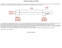 The _Morgain_ antenna for 40/80 meters is a straightforward and cost-effective wire antenna design, requiring careful tuning for optimal performance across two bands with low SWR. Construction involves creating 12 cm PVC spacers with three holes for wire insertion, along with larger terminals for anchoring and connector housing, which should be sealed with silicone. The provided measurements detail the specific lengths for the antenna elements, crucial for achieving resonance on both 40m and 80m bands. Tuning the Morgain antenna necessitates fabricating four wire segments with pins to temporarily connect and adjust the bridging points symmetrically for both 40m and 80m. This iterative process, though time-consuming, ensures the antenna functions effectively for decades once the precise connection points are soldered and protected. The design emphasizes ease of construction and long-term stability, making it a practical solution for hams seeking a dual-band wire antenna.
 -
 Multiband Center-Loaded Off-Center-Fed Dipole (CL-OCFD) antenna that work on 80m 40m 30m 20m 15m 10m. The Center-Loaded Off-Center-Fed Dipole (CL-OCFD) antenna, developed by Serge Stroobandt, offers a versatile solution for amateur radio enthusiasts, covering multiple HF bands (80, 40, 30, 20, 15, and 10 meters) without the need for an antenna tuner. This innovative design utilizes a capacitor for resonance on the 80-meter band and a resistor to manage static charges. The CL-OCFD enhances bandwidth and simplifies operation, making it a significant advancement on OCF Dipole design.
 -
 The ZS6BKW multiband HF antenna, a design by ZS6BKW (G0GSF), functions effectively on multiple HF bands without requiring an Antenna Tuning Unit (ATU) for 40, 20, 17, 12, 10, and 6 meters. This antenna, approximately **27.51 meters** (90 feet) long with a 12.2-meter (40-foot) open-wire feeder, is a direct descendant of the _G5RV_ but offers superior multi-band resonance. It can be deployed as a horizontal dipole or an inverted-vee, with the latter requiring only a single support and maintaining an apex angle of at least 90 degrees to prevent signal cancellation. Performance data, recorded with an MFJ Antenna Analyser, indicates SWR values of 1:1 on 7.00 MHz (40m) and 14.06 MHz (20m), with SWR below 1.3:1 on 17m, 10m, and 6m. While primarily designed for these bands, the antenna can be adapted for 80m, 30m, and 15m with an ATU, preferably at the balanced feeder's base. The use of 450-ohm twin-lead for the feeder is recommended over 300-ohm for improved strength and reduced losses, especially in adverse weather conditions. This design, originally published in _RadCom_ in 1993 and featured in Pat Hawker’s "Antenna Topics," provides a compact and efficient solution for HF operation, particularly for those with limited space or resources.
 -
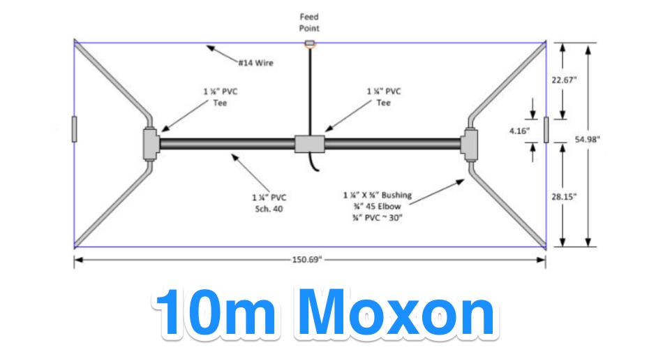 For amateur radio operators seeking a compact, directional antenna for the 10-meter band, this resource details the construction of a Moxon Yagi beam. The design utilizes readily available PVC pipe for the boom and elements, with specific measurements derived from the Moxon Rectangle Generator software. It outlines the assembly process for the main boom and end sections, providing critical dimensions for element spacing and overall length to achieve resonance at 28 MHz. The Moxon configuration offers a smaller footprint compared to a traditional Yagi, making it suitable for limited space installations. The article provides practical guidance for hams interested in a DIY antenna project, emphasizing the use of common hardware store materials. It specifies a 1 1/4" PVC schedule 40 pipe for the main boom and details the use of tees, reducing bushings, and 45-degree elbows for the element ends. Key measurements like the 55" spacing for the ends and the 150 3/4" overall length are provided, enabling replication of the design. The Moxon's inherent wide beamwidth and good front-to-back ratio make it an effective choice for DXing on 10 meters.
 -
 Presents the design and construction details for a VHF bicycle-mobile antenna, originally published in QST. The antenna utilizes a modified _Arrow J-Pole_ design, adapted for portable operation on a bicycle frame. Performance characteristics include a reported **1.5:1 SWR** across the 2-meter band, demonstrating effective impedance matching for typical handheld transceivers. Construction involves readily available materials, emphasizing lightweight components suitable for mobile deployment. The document provides a parts list and step-by-step assembly instructions, detailing the radiator and ground plane element lengths for optimal resonance at 146 MHz. Mechanical considerations for mounting on a bicycle are also addressed. The resource covers practical aspects of integrating the antenna with a bicycle, including cable routing and securing methods. It offers insights into achieving reliable VHF communications while operating in a mobile, low-power environment, making it relevant for field day activities or casual portable operation.
 -
 The resource details the construction and performance of a dual-band 40/30 meter _Moxon_ antenna, evolving from an initial single-band 30-meter design that failed in a storm. It specifies materials such as four 10-meter fishing rods, galvanized iron TV antenna support pipes, 1mm diameter PVC-covered copper wire, and a piece of 75-ohm TV satellite cable for feedline. The document outlines the iterative design process, including initial resonance measurements of 9.9 MHz for 30 meters and subsequent recalculations to shift the center frequency by 300 kHz using _Moxon software_. Initial testing on a roof yielded SWR readings of 1.4:1 at 7.200 MHz and 1.5:1 at 10.280 MHz. After installation atop a 30-meter tower, the final SWR measurements were 1.1 at 7.130 MHz and 1.4 at 10.230 MHz, with a notable 30 dB front-to-back ratio on 40 meters. The 30-meter performance, while good, showed a front-to-back ratio of approximately 15 dB, suggesting a slightly high resonance. The antenna's placement on a 700-meter hill, with a significant ground drop in certain directions, is noted as a potential factor in its excellent DX performance, enabling daily contacts with the USA West Coast on 30 and 40 meters with 100 watts.
 -
 Presents G0GSF Brian's ZS6BKW antenna, a refined iteration of the classic G5RV, offering improved performance across multiple HF bands. The design emphasizes specific radiator and ladder line lengths to achieve lower SWR on 40m, 20m, 17m, 12m, and 10m, making it a practical choice for operators seeking a single wire antenna solution. The document includes critical dimensions for the flat-top and the 450-ohm ladder line section, which are key to its multiband resonance characteristics. Unlike the original G5RV, the ZS6BKW aims for direct 50-ohm feedpoint impedance on several bands, reducing the need for an external antenna tuner. My field experience with similar optimized dipoles confirms that precise construction, particularly the ladder line length, is paramount for realizing the intended SWR benefits. This design offers a compelling alternative for hams with limited space or those preferring a less complex antenna system.
 -
 These devices are called Traps, but they are actually more like frequency sensitive switches. They are parallel resonant, high Q, tuned circuits which provide a very high impedance at their frequency of resonance.
 -
 Constructing an HF End-Fed Half-Wave (EFHW) vertical antenna, the resource details the winding of a monoband matching unit, inspired by _AA5TB_, designed to provide a 50 Ohm impedance match without a ground plane or antenna tuner. It specifies the use of a _T200-2_ ferrite core for the transformer, outlining the 13-turn secondary and 2-turn primary winding process with enamelled copper wire. The document also describes the integration of a coax capacitor, whose length is critical for tuning and varies by band, with specific starting lengths provided for 20m, 17m, 15m, 12m, and 10m operation. The practical application section guides the builder through tuning the antenna using an antenna analyzer, emphasizing the iterative process of spacing secondary windings and trimming the coax capacitor to achieve resonance at the desired band frequency. It highlights the antenna's low angle of radiation, beneficial for DX, and claims up to 2 S-points improvement over a _G5RV_ or similar doublet when used as an omnidirectional vertical. A comprehensive shopping list, including specific part numbers from _Rapid Electronics_, is provided, along with advice on selecting fiberglass fishing poles for support and suitable antenna wire.
 -
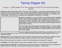 The "Tenna Dipper" is a low power antenna analyzer and ATU tuning aid. With this handy accessory, you can determine the 50 Ohm resonance frequency of antennas or you can adjust your antenna tuner for a 50 Ohm match without generating QRM
 -
 An antenna does not have to be resonant to work, as the primary reason for resonance is to eliminate the need for an impedance-matching device. A non-resonant wire dipole fed with open-wire line and an antenna tuner can function as an effective multiband antenna. Two wires are essential for powering an antenna, ideally with a balanced configuration like a dipole fed by parallel-wire line, though coaxial cable can be used with a 1:1 balun to mitigate RF feedback on the shield. Antenna gain is achieved by shaping and aiming RF energy, concentrating it in a particular direction, as seen in beam antennas or shaped radiation patterns of wire antennas. The function of an antenna tuner is to match the transceiver's 50 Ohm output to the antenna system's impedance, which can vary widely. Wire antennas do not always require center feeding; end-fed long wires or off-center-fed dipoles (Windom antennas) can be used, often requiring a counterpoise or radial system. Dipole antennas do not need to be perfectly horizontal; their legs can be bent, inclined, or even vertical, affecting feed point impedance. Vertical antennas shorter than a half wavelength necessitate a ground system, typically comprising radial wires, with more radials generally leading to greater efficiency. A 1:1 SWR indicates an impedance match but does not guarantee a good antenna, as an inefficient antenna with a poor ground system can still show a perfect SWR while wasting RF as heat. Always using the best feed line affordable is crucial for minimizing loss and maximizing RF signal delivery to and from the antenna.
 -
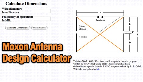 Calculates precise dimensions for **Moxon rectangle** HF antennas, enabling hams to design antennas by inputting desired resonant frequency and wire diameter. This web-based tool, version 0.5, is a PHP front-end developed by W4/VP9KF, based on a public domain BASIC program originally authored by L. B. Cebik, W4RNL. It generates critical measurements for the driven element and reflector, ensuring proper spacing and element lengths for optimal performance. User feedback confirms the calculator's accuracy, with one user reporting resonance within 50 Hz of the design frequency for an 18 MHz antenna, eliminating the need for SWR adjustments. This contrasts with other online tools that resulted in significant frequency discrepancies. The tool's precision facilitates building **directional antennas** for specific bands, contributing to effective DXing and contesting operations.
 -
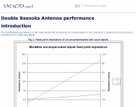 The Double Bazooka Dipole is a half wave dipole with an attempt at compensation of the reactance change that occurs around resonance for a half wave dipole.
 -
 Constructing a compact, two-band magnetic loop antenna for HF operation, especially from constrained locations like a balcony, presents unique challenges. OK1FOU's design, inspired by DJ3RW's 50 MHz loop, addresses these by employing an unusual side-fed configuration and placing the symmetric, two-section variable tuning capacitor at the bottom of the loop, directly connected to the coax shield. The article provides specific material recommendations, including two 1-meter wooden pales and about 3 meters of thick loudspeaker cable, noting the high current (60A at 100W) in the loop. Construction steps detail forming two turns with a 5 cm gap, using a GDO to pre-tune the open loop to a frequency slightly above the desired highest band, and then integrating the tuning and coupling capacitors. For 10/14 MHz, an open loop resonance of 16-17 MHz is suggested. Practical experience with the 10 MHz band from a third-floor balcony in Prague (JO70GC) shows a 1:1 SWR across most of the band without an external ATU. While DX traffic was modest due to the urban environment, QSO examples with RA6WF, LA6GIA, G0NXA, and LZ1QK on 10 MHz are provided, demonstrating its operational capability.
 -
 An antenna system is more easily interfaced to a radio when the input reactance at the feedline terminals is low or close to series resonance
 -
 Presents a comprehensive guide for constructing a broadband Hex Beam antenna, a popular directional array for HF operation. This design offers a compact footprint and excellent gain characteristics, making it suitable for limited space installations while providing significant performance advantages over omnidirectional antennas. The resource details the specific dimensions for a five-band Hex Beam covering 20, 17, 15, 12, 10, and 6 meters, emphasizing the critical element spacing and wire lengths required for proper resonance and pattern. It outlines the construction of the center post, spreaders, and wire elements, along with the feed point assembly, ensuring proper impedance matching. The project aims for a forward gain of approximately **5.5 dBi** on most bands, with a front-to-back ratio often exceeding _20 dB_. Building this antenna requires careful measurement and assembly, but the resulting performance provides a substantial upgrade for DXing and contesting.
 -
 The K0RWU 75-meter mobile antenna design features a 7.5-foot overall length, incorporating a 2.5-foot loading coil wound with #20 enamel wire on a 1/2-inch fiberglass rod, subsequently covered with 1/2-inch shrink tubing to increase diameter to 3/4 inch. This configuration achieved resonance at 3965 kHz with a 5-foot stainless steel whip. The antenna integrates a matching transformer, identified by larger turns near the PL259 connector, and is constructed using a modified Radio Shack CB antenna base. Construction involves drilling and epoxying a 1/2-inch fiberglass rod into a PL259 connector, feeding #20 enamel wire through the rod, and winding 17 turns of #18 matching coil wire between the PL259 sleeve and the center feed point. The main loading coil fills the 2.5-foot rod section. The design allows the antenna to bend for garage clearance and emphasizes maintaining a 50-ohm feed impedance to prevent vehicle electrical damage. The author also discusses experiences with a Yaesu ATAS-100 motorized antenna and a 10-meter antenna project, noting issues with auto couplers and the ATAS-100's performance on 17 meters. Future modifications considered include adding a small servo for band spreading and increasing the fiberglass rod length for a 3-foot loading coil to improve bandwidth. The antenna's sharp tuning, between 3960 kHz and 3970 kHz, necessitates careful adjustment of coil turns for optimal VSWR.
 -
 Presents the Light Loop, a small magnetic loop antenna optimized for 40m through 10m operation, demonstrating its construction for portable QRP use. The design emphasizes lightweight materials and a compact form factor, making it suitable for handheld or backpack deployment during field activities. It details the primary radiating element, the coupling loop, and the variable capacitor required for resonance across the specified HF bands. The article provides specific component choices, such as the 1.5-inch diameter aluminum tubing for the main loop and the 10-365 pF variable capacitor for tuning. It discusses the importance of precise loop circumference and spacing for efficient impedance matching and bandwidth characteristics. The resource includes practical advice on achieving resonance and optimizing performance for low-power transceivers. Construction notes cover the mechanical assembly, including mounting the capacitor and feedpoint connections. It highlights the antenna's suitability for pedestrian mobile operations, offering a practical solution for HF communication without extensive setup. The design aims for a balance between portability and effective radiation on the lower HF bands.
 -
 Demonstrates the iterative design and construction of a **tapped HF/VHF mobile vertical antenna** by K0EMT, detailing four generations of development. The antenna supports operation on 80m, 40m, 30m, 20m, 17m, 15m, 12m, 10m, 6m, and 2m bands. Initial designs, like Generation 1, featured a 3/8" x 24TPI bolt in a PVC end cap with a 1" aluminum tubing mast, resulting in a 9'9" overall length and resonance around 6.9 MHz with the full coil. Subsequent generations refined the mast and coil forms, transitioning from aluminum to copper tubing (Generation 3, found too weak) and eventually fiberglass for the coil form (Generation 4, in progress). Coil tapping points were adjusted to achieve resonance without an external tuner in Generation 2. The project outlines material costs, totaling approximately $25, and mentions a successful 28 MHz QSO with EA3XA using an ICOM IC-706 mk II at 100 Watts. For 80m operation, an external wire with the maximum coil setting is used, or a 56" extender below the coil for stationary use.
 -
 The resource provides an in-depth analysis of the W6NL 40m _Moxon Yagi_ antenna, utilizing a NEC-2 model to simulate its performance. It details the antenna's design parameters, including element lengths and spacing, and explores critical operational aspects such as feedpoint impedance, SWR across the 40-meter band, and radiation patterns. The document systematically presents the model's setup and the methodology for evaluating the antenna's behavior in different environments, including free space and over real ground. Performance data derived from the NEC-2 model illustrates the antenna's forward gain, front-to-back ratio, and beamwidth. For instance, the model predicts a free-space gain of approximately **6.5 dBi** and a front-to-back ratio exceeding **20 dB** at resonance. Comparisons are drawn between free-space performance and operation at various heights above average ground, demonstrating the impact of ground proximity on take-off angle and overall efficiency. The analysis also touches upon the antenna's bandwidth characteristics, indicating its suitability for the entire 40-meter band with acceptable SWR.
 -
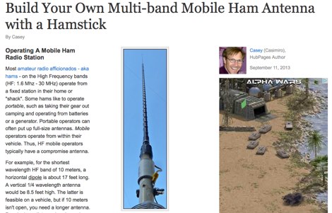 Constructing an effective mobile antenna system for HF bands often presents challenges in achieving multi-band operation with a compact footprint. This project details the assembly of a versatile mobile antenna utilizing a standard _Hamstick_ base, enabling operation across 40, 20, 15, and 10 meters. The design incorporates a 102-inch whip and a custom-fabricated coil, allowing for quick band changes by adjusting the coil tap point. The document provides a parts list, step-by-step assembly instructions, and tuning considerations for optimizing SWR on each band. It emphasizes practical construction techniques for the coil and mounting hardware, ensuring mechanical integrity for mobile use. The antenna's performance is discussed in the context of typical mobile operating environments, highlighting its adaptability for various HF frequencies. Final adjustments involve precise trimming of the whip and coil taps to achieve resonance, with a focus on minimizing losses and maximizing radiation efficiency.
 -
 Presents a construction project for a linear-loaded 40-meter rotatable dipole, detailing the design evolution from mid-element coils to 300-ohm twinlead loading. It covers material selection, including repurposed fishing poles and EMT conduit, and outlines the assembly process for the antenna elements and mounting plate. The resource provides specific measurements for element lengths and linear loading sections, along with SWR plots demonstrating the antenna's resonance at 7.035 MHz with a 1.1:1 SWR, and bandwidth up to 7.120 MHz below 2:1 SWR. The article documents the antenna's performance during various RTTY and CW contests, including the SARTG RTTY and SCC RTTY contests in August 2006, and the ARRL DX CW and CQWW WPX RTTY contests in February 2007. It reports successful operation at 500-1000W, noting improved performance after replacing a faulty coax cable. Specific DX contacts from British Columbia, including stations in Europe and South Africa, are listed, illustrating the antenna's capability despite its shortened length and relatively low height of 55 feet. The content highlights practical considerations such as weatherproofing the connections and supporting the fiberglass elements to prevent sagging. It also includes a brief comparison to an inverted-V at similar height and a ground-mounted vertical, noting the rotatable dipole's quieter reception. The author shares insights into the iterative design process and tuning adjustments made to achieve optimal resonance.
 -
 Demonstrates the design and construction of a compact, portable multi-band mini-delta loop antenna, specifically optimized for /P (portable) operations from remote locations like Scottish islands. The resource covers the theoretical underpinnings of half-wave loops, contrasting closed and open configurations, and then details the application of a folded dipole principle to achieve a 50-ohm match for direct coax feed. It presents empirical formulas for calculating element lengths, considering the velocity factor of common wire types, and provides a detailed example for a 20m (14.175 MHz) version. The article includes a comprehensive table of dimensions and allowances for a five-band (20m, 17m, 15m, 12m, 10m) mini-delta beam, along with construction hints for the central support and balun. It specifies a 1:1 trifilar balun wound on a ferrite rod and describes the antenna adjustment process using an _MFJ-259B Antenna Analyser_. Initial test results indicate an SWR of 1:1 at resonance and a bandwidth of approximately 240 kHz on 20m, even at a low height of five feet above ground. The distinctive utility lies in its focus on a practical, easily deployable beam antenna for portable DXing, offering a viable alternative to more complex or larger arrays.
 -
 GW4ALG's _136 kHz Pages_ document the evolution of vertical antennas for the 2200m band, starting with a prototype mounted on a house wall. This initial design, despite achieving the first **395 km** GM-GW QSO, suffered from significant insulation breakdown, high RF losses due to proximity to the house, and difficult tuning adjustments. The author details the challenges of maintaining resonance and matching with a variometer in the loft, noting that adding three earth spikes offered no measurable improvement over a simple water tap connection. The subsequent experimental 12m vertical, relocated away from the house, significantly reduced dielectric losses and proved far more effective. This antenna enabled GW4ALG to set a world DX record on 136 kHz with a **1916 km** QSO to OH1TN, and an intra-UK record of **703 km** to GM3YXM/P. The resource further explores the use of helium-filled balloons to extend the vertical radiator, achieving heights up to 27m, typically 20m, for enhanced low-band performance. Practical advice on balloon types, inflation, and critical insulation between the wire and balloon is provided, emphasizing safety and avoiding arcing.
 -
 A 500-watt mobile antenna project details the conversion of an old 10m hamstick into a highly efficient, multiband "bugstick" for HF operation. The core modification involves replacing the original coil with 25 turns of 6 turns-per-inch, 1.5-inch diameter coil stock, fabricated from #14 wire. This design, intended for a 3-magnet mount on a vehicle cab, achieves resonance on multiple bands by shorting out specific turns on the coil, similar to a **bugcatcher** antenna. Measurements taken with an MFJ-259 analyzer on a GMC pickup show 0 turns shorted for 20 meters (14.2 MHz), 10 turns for 17 meters, 16 turns for 15 meters, 19 turns for 12 meters, and 23 turns for 10 meters. The construction emphasizes using UV-resistant tie-wraps and #14 solid wire with crimp lugs for robust RF connections, bypassing the fiberglass rod for current flow. A bonus section details a 40-meter version, utilizing 48 turns of 8 TPI, 2-inch diameter coil stock.
 -
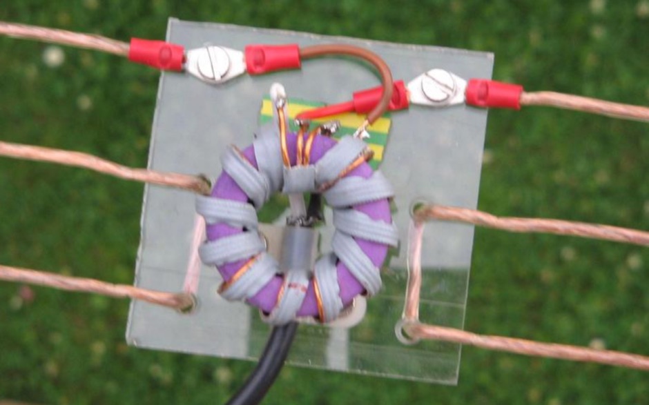 This QRZ.com callbook entry by DL6GD details the construction and performance of a **40m/80m Morgain folded dipole antenna**. The resource includes a schematic diagram, construction photos, and tuning notes. The antenna, with a total length of **20.30m**, was mounted at a height varying from 4m to 6m above ground. Construction utilizes 0.75 sq mm transparent insulated copper wire, with Plexiglas spreaders (5mm thick, 70x10mm) spaced at 25mm intervals, secured with hot glue. A waterproof junction box houses the feedpoint and balun. Tuning involved adjusting wire bridges for resonance on each band. On 80m, an SWR of **1.1:1** was achieved at 3.657 MHz, with an SWR of 2.7:1 at 3.580 MHz and 2.5:1 at 3.755 MHz, yielding a bandwidth of 175 KHz. For 40m, an SWR of **1.1:1** was measured at 7.100 MHz, with 1.5:1 at 7.000 MHz and 1.3:1 at 7.200 MHz, providing a 200 KHz bandwidth. DL6GD notes that 80m tuning exhibits slight height sensitivity, while 40m tuning is less affected by height or 80m adjustments. Long-term observations from 2014 and 2022 document SWR degradation due to environmental factors like spiderwebs and ice accumulation, which can cause HF-conductive paths between elements. DXZone Focus: Callbook Entry | 40m/80m Morgain Dipole | SWR Measurements | 20.30m Length
 -
 The **2M Moxon antenna** design presented operates at 144 MHz, providing a compact, directional solution for VHF communications. Construction involves aluminum tubing for the elements, with specific dimensions for the driven element and reflector to achieve optimal performance. The design aims for a good front-to-back ratio and a relatively low SWR across the 2-meter band, making it suitable for portable or fixed station use where directivity is beneficial. Element lengths are critical for proper resonance and pattern. The driven element measures approximately 38.5 inches, while the reflector is slightly longer at 40.5 inches. Spacing between the elements is 12 inches, forming the characteristic Moxon rectangle. This configuration yields a gain of about 5.5 dBi and a front-to-back ratio exceeding 20 dB, which is advantageous for reducing interference from unwanted directions. Feedpoint impedance is close to 50 ohms, allowing direct connection to coaxial cable without complex matching networks. The antenna's lightweight structure, typically under 2 pounds, facilitates easy deployment and rotation, making it a practical choice for field operations or as a compact home station antenna.
 -
 Detection and recording of Schumann resonances and other electromagnetic phenomena at frequencies below 50 Hz By Hans Michlmayr
 -
 Optimizing the ZS6BKW antenna for full HF band coverage often requires specific modifications beyond its standard configuration. This resource details several enhancements, beginning with a simple series capacitor to improve 80m SWR, a technique W5DXP found effective for permanent installation due to its minimal impact on higher bands. Further improvements include a 10-inch parallel open stub for 10m resonance, shifting the frequency to 28.4 MHz with an SWR of approximately 1.8:1, a practical solution for Technician class operators. The document then explores a switchable matching section, adding or subtracting one foot of ladder line at the 1:1 choke-balun, which significantly impacts higher frequency bands and eliminates the need for a tuner on 17m. W5DXP's _AIM-4170D_ antenna analyzer measurements confirm these effects. More advanced modifications involve a parallel capacitor for further 80m SWR reduction, requiring remote switching for multi-band operation, and relay-switched parallel capacitors at specific points on the 450-ohm matching section to achieve low SWR on 60m, 30m, and 15m. These detailed steps, including _Smith chart_ analyses for the challenging bands, aim to transform the ZS6BKW into a truly all-HF-band antenna, reflecting W5DXP's practical experience in antenna tuning.
 -
 A 2-meter Moxon beam antenna, designed for the _144 MHz_ band, is detailed, originating from a desire to participate in the PW 2m QRP contest. The design, based on a Moxon Rectangle, offers a compact directional solution for VHF portable operations. The author, G0KYA, constructed the antenna using readily available materials like 15mm plastic conduit for the frame and 1.5mm copper wire for the elements. Initial testing with an MFJ-259B antenna analyzer showed a **1.2:1 SWR** at 144.300 MHz, indicating good resonance. The antenna's compact size, approximately 70cm x 40cm, makes it highly suitable for portable QRP work, providing a significant advantage over an omnidirectional vertical. The project includes practical advice on element spacing and construction techniques, emphasizing ease of assembly for field deployment. Field results from a local hilltop demonstrated the Moxon's directional characteristics, allowing for effective nulling of local noise and improved signal reception from specific directions.
 -
 A Variable Base-Loading-Coil provides a practical solution for optimizing HF mobile whip performance across multiple bands. The design, as presented by VK4ADC, details a coil wound on a 50mm PVC former, utilizing 1.6mm enamelled copper wire for robust construction. This approach allows for precise tuning, a critical factor in achieving efficient radiation from a mobile setup, where antenna length is often compromised. My own field experience with similar base-loaded whips confirms the importance of a well-designed loading coil for maximizing signal strength and minimizing SWR. The VK4ADC design incorporates a sliding contact, enabling continuous adjustment, which is superior to fixed taps for fine-tuning resonance on the fly. This variable inductance allows the operator to quickly adapt the antenna to different HF segments, from 80 meters up to 10 meters, without needing to swap out multiple coils. The document includes specific winding data, such as the number of turns per inch and the overall length of the coil, which are essential for replication. It also touches upon the mechanical aspects of integrating the coil with a standard mobile whip, ensuring a stable and weather-resistant assembly for reliable operation during mobile DXing or casual rag-chewing.
 -
 Showcasing a specialized product line, Advanced Receiver Research presents a comprehensive catalog of **low noise preamplifiers** and microwave **Gunnplexers**. The offerings span a broad spectrum of radio frequencies, from VLF, LF, MF, and HF bands up through VHF, UHF, and microwave, catering to diverse applications including amateur radio, commercial installations, and military systems. Their product range includes mast-mount preamplifiers, inline attenuators, power dividers, and various coaxial components. My own experience with similar low-noise front ends for weak-signal work on 2 meters and 70 centimeters underscores the critical role such components play in maximizing receiver sensitivity, especially when chasing distant DX or engaging in EME. The detailed product descriptions and technical specifications provided on the site allow operators to select the optimal preamplifier for their specific band and noise figure requirements, essential for improving signal-to-noise ratio. The site also lists specialized products for unique applications like Nuclear Magnetic Resonance (NMR) and Studio Transmitter Links (STL), demonstrating a depth of engineering capability beyond typical amateur radio fare. This breadth of offerings, coupled with clear ordering and warranty information, positions Advanced Receiver Research as a key supplier for high-performance RF components.
 -
 Ever need a way to estimate the amount of wire to add to or remove from a center-fed wire dipole antenna to achieve resonance at a desired frequency? This article help to determine correct wire lenght.
 -
 The ZS6BKW multi-band antenna, an optimized variant of the classic G5RV, is presented with detailed construction and tuning instructions. This resource outlines the antenna's design principles, which were developed by _Brian Austin (G0GSF)_ using computer programs and Smith charts to achieve optimal dimensions. It provides specific guidance on calculating and adjusting the lengths of the radiators (L1) and the matching ladder line (L2), emphasizing the critical role of velocity factor (VF) in achieving resonance. The article includes a step-by-step procedure for empirically determining the VF of ladder line using an antenna analyzer, ensuring accurate physical lengths for the matching section. It details the tuning process for the radiators, offering practical tips for incremental adjustments to achieve the best SWR curve. The resource presents SWR measurement results obtained with an _AIM-4170C_ analyzer across multiple bands, alongside predicted SWR graphs from an AutoEZ model. It confirms successful contacts on 80, 40, 20, and 17 meters, including a **17-meter DX contact** to Italy. EZNEC and AutoEZ models for the ZS6BKW antenna, covering 80 through 6 meters, are provided for download, allowing further analysis and customization. The document specifies component details, such as the use of Wireman 554 ladder line and #14 AWG THHN copper wire, and discusses the antenna's performance characteristics, noting high SWR on 15 and 30 meters but successful tuning on 6 and 80 meters with an external tuner.
 -
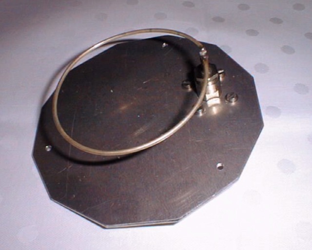 A parabolic dish ring feed optimum resonance frequency of 1325MHz
 -
 The resource details the construction of a multiband trap-style Inverted-V antenna designed for operation on 3.5 MHz, 7 MHz, 14 MHz, 21 MHz, and 28 MHz. It presents specific winding data for the traps, including the number of turns, wire gauge, and coil former dimensions, crucial for achieving resonance on the target bands. The document provides a parts list and a diagram illustrating the antenna's physical layout and trap placement. It outlines the process for building the traps using PVC pipe formers and specifies the required capacitor values for each trap. The design emphasizes a practical approach to achieving multiband operation with a single feedline, a common goal for HF operators with limited space. The document includes a table with antenna segment lengths for each band, allowing for precise replication of the design. It also offers insights into tuning and adjustment, ensuring the antenna performs optimally across the designated amateur radio bands.
 -
 DK7ZB's fan dipole designs address the challenge of operating multiple HF bands with a single feedline, providing practical construction details for **multiband wire antennas**. The resource outlines specific lengths for half-dipoles across various band combinations, including 10-15-20m for classic bands and 12-17-30m for WARC bands. It emphasizes the importance of proper spacing between resonant elements to avoid impedance interaction and high SWR, a common issue when frequencies are too close. The article details the use of **current baluns** built with FT240-43 or FT140-43 cores, specifying turns and cable types for 1KW and 400-Watt power levels. It includes a correction table for adjusting dipole lengths based on frequency shifts, aiding in fine-tuning resonance. The 20+40m dipole is noted for its ability to operate on 15m with an ATU, demonstrating versatility.
 -
 Do you want to measure antenna impedance at resonance? With this Antenna Scope, you have a simple RF Bridge for getting started in an exciting part of Ham Radio, building your own Antennas that work well
 -
 The **136kHz Vertical Antenna** at G3YMC employs a Butternut HF2V structure, standing 10m tall. It integrates a 6.5mH loading coil to achieve resonance, with a matching transformer for impedance adjustment. The antenna's configuration includes top loading via a 12m horizontal wire, enhancing capacitive impedance. Initial measurements indicated a high impedance of around 300 ohms, necessitating a transformer for a 50-ohm match. Despite challenges with ground losses, the vertical antenna has shown improved performance in specific directions, filling nulls present in the previous loop antenna setup. The tuning remains broad, with variations due to environmental factors affecting the matching. Ongoing adjustments and comparisons with the loop antenna will continue to refine its effectiveness.