Search results
Query: beam antennas
Links: 87 | Categories: 3
-
 High Performance Lightweight Antennas. The spider beam is a full size lightweight tribander yagi for 20/15/10m, made from fiberglass and wire. It has been specially developed as a highly efficient antenna for dx-pedition and portable use.
 -
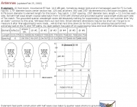
 For radio amateurs considering homebrew antenna projects, this resource details several designs from WE6W, an experienced operator. It covers the construction and characteristics of a _160 Meter QRP Loop Antenna_ optimized for high voltage, along with standard and folded variations of the double bazooka antenna. The site also presents a unique Field Day antenna design and instructions for building a Sterba Curtain, a directional array known for its gain. Each design includes practical insights from the author's building experience. The author provides comparative data, such as the performance of a standard bazooka against a traditional dipole, offering real-world context for antenna selection. The Sterba Curtain section includes notes on its beamwidth and gain, crucial parameters for directional operation. These designs are suitable for hams looking to experiment with cost-effective, high-performance antennas for various bands and operating scenarios, from QRP on 160m to directional DXing with a Sterba Curtain, which can offer significant forward gain, often exceeding **10 dB**.
 -
 4 Element Cubical Quad, Yagis, LZA Circular Quad, Shrunken Quad , quarter wave, J-Pole, beam mounting , changing polarity
 -
 Details the construction and optimization of antenna systems for amateur radio satellite operations, focusing on practical, homebrew solutions for VHF/UHF bands. It covers building _groundplane antennas_ from salvaged materials, recycling old beam antennas into new configurations like a 2-meter crossed yagi, and constructing a 10-meter horizontal delta loop. The resource also explains antenna matching techniques, including folded dipole driven elements and quarter-wave transformers, along with the importance of accurate SWR measurements and minimizing coax loss. Demonstrates how to achieve a **1:1 SWR** by carefully trimming elements and adjusting radial angles on groundplane antennas. It provides insights into selecting appropriate coax and connectors, highlighting the benefits of Belden 9913 for low loss and the proper installation of _N-connectors_. The article also addresses RFI mitigation from computer birdies and presents a design for a silent triac antenna control circuit, offering practical solutions for common satellite station challenges.
 -
 80m to 23cm beam antennas, oscar antennas, and antenna rotors
 -
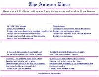 Here you will find information about wire antennas as well as directional beams.
 -
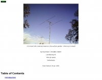
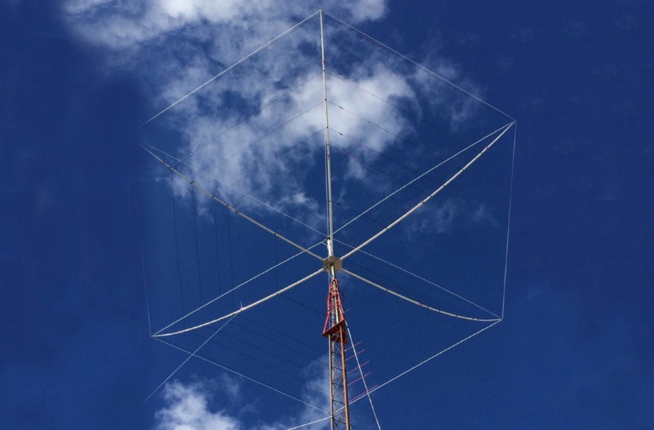
 The page provides detailed information about the construction of a full-size 160M 3 element beam antenna and an 80M 5 element beam antenna on a 330ft tower. It includes specifics about the tower height, types of antennas, elements, gain, take off angles, front-to-back ratio, operating frequencies, weight, and dimensions of the beams. The content is aimed at amateur radio operators interested in building high-performance antennas for the 160M and 80M bands. This Antenna is now been destroyed and is no more operational.
 -
 HF Vertical and Beam Antennas, antennas accessories by Butternut. Bencher is out ouf ham radio business. Recently company products has been sold to Vibroplex and DX Engenieering.
 -
 Selecting an appropriate antenna system for shortwave broadcasting involves evaluating various types based on performance, cost, and operational parameters. This resource details the critical specifications for broadcast antennas, including average and peak power ratings, directivity, takeoff angle (TOA), horizontal beamwidth, and gain, emphasizing that a 100-kW transmitter requires an antenna rated for 150 kW average and 400 kW peak. It clarifies that low TOA signals travel thousands of kilometers, while high TOA is for local coverage, and nearly all modern shortwave broadcast antennas are horizontally polarized. The article explores specific antenna types, such as Log-Periodic Antennas (LPAs), which offer wide frequency ranges (e.g., 2-30 MHz) and directional patterns with 11 dBi gain, costing from $20K to over $100K for multi-curtain versions. Dipole arrays, also known as curtain antennas, are prevalent in international broadcasting, featuring steerable beams (±15° and ±30°) and mode-switching capabilities to alter TOA, with high/low pairs costing over $1 million. Fan dipoles are noted for omnidirectional patterns, smaller size, and lower cost for low-power applications, while rhombics, though simple, require resistive termination and incur several dB of I2R losses. Balun considerations are crucial, as most communications baluns are not rated for the higher average and peak powers of AM broadcast transmitters. Modern shortwave antennas utilize durable materials like Alumoweld wire rope for radiators and support elements, avoiding copper, fiberglass, or materials prone to stretching or deterioration. Feeder systems for high-power stations often require tapered-line baluns to convert 50-ohm unbalanced power to 300-ohm balanced for connection to the antenna.
 -
 Interesting article on mobile antennas by Cebik. . The article offers advice for setting up and operating mobile antennas for ham radio use. It emphasizes the lossy nature of mobile-in-motion antennas but encourages users to rise to the challenge. Steps include safeguarding car electronics, choosing proper cabling, and carefully selecting and mounting antennas. It highlights potential issues like roof mounting, trunk lip grounding, and side-mounting for trucks. For stationary operation, options like dipoles or beams are explored, with safety tips for masts and guying systems. Lastly, it stresses safety, suggesting stopping the vehicle to operate whenever possible
 -
-
 Simple gain antennas for the beginner, a 2 element HF yagi antenna
 -
 8 and 4 elemets yagi beam antenna by N6CA
 -
 MQ-1 four band HF beams 20,15,10,6 meters MQ-2 six band HF beams 20,17,15,12,10,6 meters, beam antennas and Hybrid Quad antennas
 -
 A Moxon rectangle antenna projects for the 6 10 15 17 and 20 meter band but include drawings, plans, statistics and homebrewing statistics.
 -
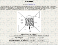 Two element X-Beam is a high-performance broad-band antenna that is ideal for Ham radio operators with limited space. X-Beams are inexpensive and easy to build. The performance of the simple X-beam is amazingly similar to larger, more conventional antennas by 4S7NR
 -

-
 A javascipt online calculator for 2 and 3 element beam antennas. Just input frequency and will diplay element dimensions and spacing. Measurements in Feet and Meters by G4VWL
 -
 The document details the optimization and construction of the _Maria Maluca_ antenna, a compact 6-band (20m-6m) directional beam. It presents a comparative analysis of shortwave antenna principles, highlighting the efficiency gains achieved by using an open feeder line and tuner as a resonant unit, contrasting this with the losses associated with traps or capacitive loads in multiband antennas. The resource specifically revisits an older South American 2-element design for 10, 15, and 20 meters, applying modern NEC-based software to develop a six-band version. Performance data is meticulously tabulated, showing impedance, free space gain, gain at 12m height, elevation angle, and front-to-back (F/B) ratio for each band from 20m through 6m. For instance, on 15m, the antenna achieves 5.1 dBd free space gain and 13.72 dB F/B ratio. The construction section provides practical guidance on element assembly using aluminum pipes and hose clamps, detailing the use of a heavy-duty glass fiber reinforced polyamide rod for electrical separation and bending strength. It also specifies the use of 450-ohm _Wireman_ line CQ 552 for the transmission line. The document includes diagrams for rod fixing, an air-wound balun, and a vertical elevation diagram for the 15m band, illustrating its DX qualification. It also discusses the antenna's suitability for portable and expedition operations, noting its compact transport dimensions (max 1.50m length, 12 lb weight) and quick assembly time (under 15 minutes). The author, Dipl.Ing. Helmut Oeller, DC6NY, is identified as a source for material kits.
 -

-
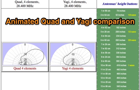 Animated quad and yagi comparison. You can see antennas' characteristics behavior in a vertical plane with changing of the height.
 -
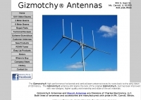 The Charles Gizmotchy high performance horizontal and vertical beam antennas. Two, Six, Ten and eleven meters antennas
 -
 A compact Beam Antenna That Can Be Built At Home. Made with lightweight wooden "X" frame with two folded and linear loaded wire elements. The two elements are approximately a half-wave each.
 -
 JJ0DRC's HF multi-band delta loop antenna project, initially conceived during the waning peak of Cycle 23, addresses the common challenge of achieving effective DX operation from a small residential lot in Japan. Dissatisfied with a ground plane antenna's performance in SSB pile-ups, the author sought a beam-like solution without a tower, drawing inspiration from a JJ1VKL article in CQ Ham Radio Sep. 2000. The antenna, constructed in October 2000, employs two 7.2-meter fishing rods (37% carbon fiber, reinforced with cyano-acrylate glue and aluminum tape) and 1mm enameled wire, fed by an Icom AH-4 external antenna tuner. While the exact beam pattern remains unmeasured, JJ0DRC observed a significantly higher callback rate compared to dipole antennas, particularly on higher bands. The system's circumference length of 15-20m is crucial for maintaining a good beam pattern across HF bands, though performance on lower bands like 80m, 40m, and 30m becomes less directional as the length deviates from a full wavelength. Ongoing maintenance addressed degradation issues, including aluminum tape cracking and wire breakage at connection points due to strong winds (often exceeding 10-15m/s in winter). The author reinforced rod connections with IRECTOR PIPE SYSTEM components and INSU-ROCK ties, and improved wire attachment methods using Cremona rope and epoxy bond to enhance durability.
 -
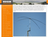
 Presents a comprehensive guide for constructing a broadband Hex Beam antenna, a popular directional array for HF operation. This design offers a compact footprint and excellent gain characteristics, making it suitable for limited space installations while providing significant performance advantages over omnidirectional antennas. The resource details the specific dimensions for a five-band Hex Beam covering 20, 17, 15, 12, 10, and 6 meters, emphasizing the critical element spacing and wire lengths required for proper resonance and pattern. It outlines the construction of the center post, spreaders, and wire elements, along with the feed point assembly, ensuring proper impedance matching. The project aims for a forward gain of approximately **5.5 dBi** on most bands, with a front-to-back ratio often exceeding _20 dB_. Building this antenna requires careful measurement and assembly, but the resulting performance provides a substantial upgrade for DXing and contesting.
 -

-
 Located in France, DXBeam designs and manufactures a range of monoband, dual band and triband antennas, rotary dipoles, Moxons and Yagis
 -
 G3TXQ pages focuses on understanding the HexBeam antennas. Basics, dimensions, multi band issues, antenna modeling.
 -
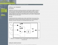
 Solves antenna matching problem with two phased antennas. Stacked rotary beams are popular. However, connecting two 50 Ohm antennas together presents some problems.
 -
 In these slides, differences between spiderbeam antenna and hexbeam antennas are explained comparing performances and measurements.
 -
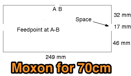 A moxon antenna project for 70 cm band, test and results of this popular antenna model applies to UHF bands.
 -
 NEC4WIN is a 32 bits commercial antenna simulation software based on MININEC3 developed by the Naval Ocean Systems Center in the 70s and 80s. It runs under Windows and can be used to simulate, analyze and optimize wire antennas, beams, verticals, etc. NEC4WIN has limitations. They are the same as Mininec3 on which the engine is based.
 -
 Electronically controlled HF antennas. General coverage. Top features on all ham bands. Very advanced materials and state of the art technology.
 -
 Nowdays lots of people are putting up antennas to either beam in different directions at the same time or just to stack them and get a lower angle of radiation. Use this stackmatch to match you array.
 -
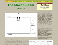 Notes on moxon antennas for VHF and HF bands. Main characteristics, gain and f/b ratio by DK7ZB
 -
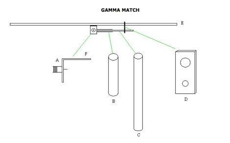 how to make a gamma match for a antenna. The Gamma match is the most used matching device used for yagi beams.
 -
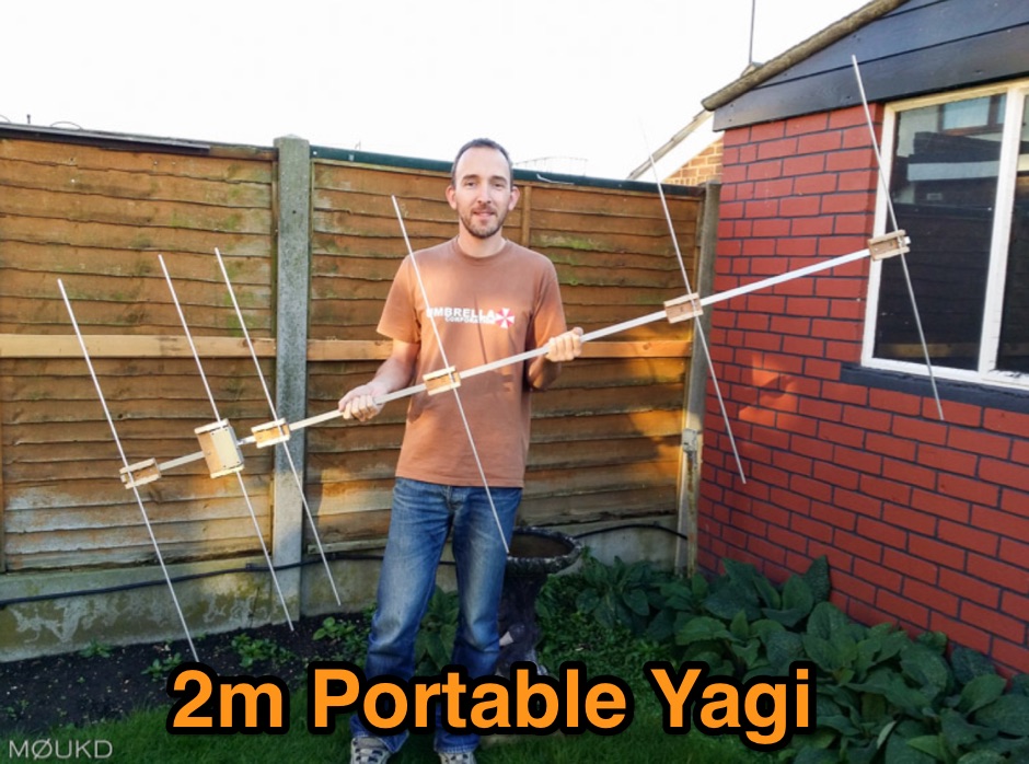 Building a 2 metre 144MHz VHF Yagi beam antenna, designed for portable use.
 -
 Dedicated to State-of-the-Art lightweight portable radio. Sotabeams produces and sells amateur radio products dedicated to ham radio portable operations. Antennas, supports and masts, filters, wires and more accessories for amateur radio.
 -
 A ATU for beam and vertical antennas by PA0FRI
 -
 A fractional bandwidth of up to 30:1 characterizes spiral antennas, making them highly effective across a very wide frequency range, often from 1 GHz to 30 GHz. The resource details two primary types: the **Log-Periodic Spiral Antenna** and the **Archimedean Spiral Antenna**, defining each with specific polar functions and illustrating their planar configurations. It explains that spiral antennas are typically circularly polarized, with a Half-Power Beamwidth (HPBW) of approximately 70-90 degrees, and a peak radiation direction perpendicular to the spiral plane. The content elaborates on critical design parameters affecting radiation, including the total length (outer radius) for lowest frequency, the flare rate ('a' constant) for optimal radiation versus capacitive behavior, the feed structure (often an infinite balun) for high-frequency operation, and the number of turns (typically 1.5 to 3 turns). It also discusses the theoretical impedance of 188 Ohms for Log-Periodic spirals, derived from Babinet's Principle, noting actual impedances are often 100-150 Ohms. The article presents a simple construction method for an Archimedean spiral, demonstrating VSWR and efficiency measurements. Measurements from a constructed spiral antenna show a VSWR that is fairly constant across the band, albeit with a mismatch loss of about 3 dB. The antenna efficiency remains around -5 dB (31.6%) across its operating range, indicating a decent wideband radiator despite opportunities for optimization.
 -
 The Gizmotchy high performance horizontal and vertical beam antenna for 2/6/10/11 meter bands
 -
 Antenna dealer, antenna masts, towers, mounts, antenna rotators, steppir and optibeam inrad dealer
 -
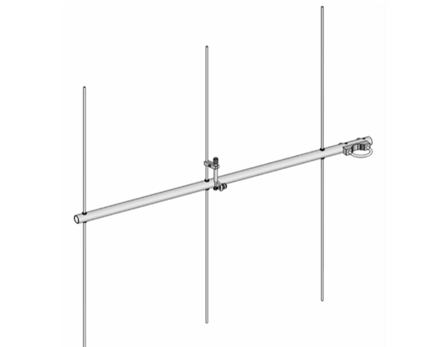
 Ground Plane - 1/4 wave vertical, J-Pole, 3 Element Yagi Beam and simple antenna supports
 -
 Fabricates baseplate components, and provides hardware kits for DIY hex beam, spiderbeam and moxon antennas.
 -
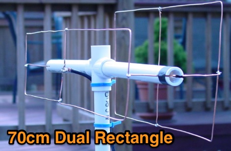 The antenna described here is a direct-connect dual-rectangle beam for use on 70 cm between 440 and 450 MHz
 -
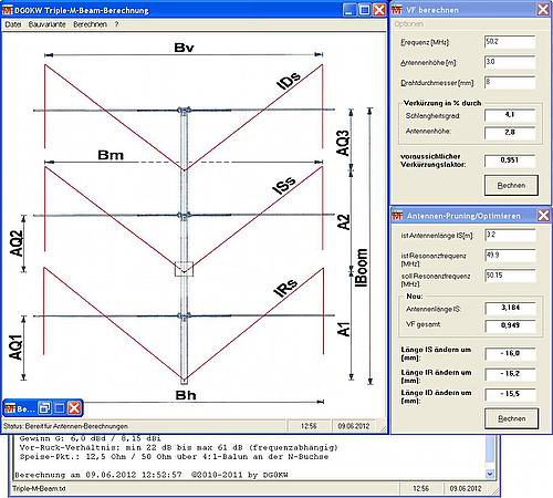 The Triple-M-beam calculation program is used for the calculation of Triple-M-beam antennas by DG0KW
 -
 Spanish HexBeam antenna manufacturer, produce antennas kits, and part for HexBeam antennas
 -
 MW0JZE Manufacturer of the G3TXQ Broadband Hexagonal Beam - HexBeam Antennas
 -
 HF Beam Calculator for Amateur Radio and CB Communications
 -
 Constructing a compact directional antenna for the 17-meter band, this resource details the build process for a Moxon rectangle, a two-element Yagi variant with folded-back elements. It covers the antenna's evolution from the _VK2ABQ beam_ and provides specific dimensions for a version built using fishing pole whips. The content includes a discussion of the antenna's radiation pattern, feedpoint impedance, and its inherent front-to-back ratio, which is often superior to a standard two-element Yagi. Practical considerations for element spacing and material choices are also addressed, alongside a visual representation of the antenna's physical layout. Performance data presented includes a comparison showing the Moxon rectangle's **2.5 dB gain** over a half-wave dipole and a front-to-back ratio of **20 dB**. The resource also touches upon the antenna's relatively wide bandwidth for a two-element beam and its suitability for portable operations due to its compact footprint. It offers insights into optimizing the design for specific operating conditions and discusses the advantages of its lower take-off angle compared to omnidirectional wire antennas, making it effective for DX contacts on the 17-meter band.