Search results
Query: transmission line
Links: 97 | Categories: 4
-
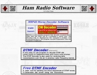 MRP40, a successor to the well-regarded MRP37, offers robust Morse code decoding capabilities by processing analog audio signals via a sound card and displaying the decoded text on a computer monitor. My own field tests with similar sound card decoders confirm that the quality of the audio input and proper signal conditioning are paramount for achieving reliable decoding, especially with _weak signals_. The program also facilitates CW transmission, converting keyboard input into Morse code to key a transceiver, a feature I've found useful for practicing sending or for quick contest exchanges. Beyond its core CW functions, MRP40 incorporates a convenient mini-logbook, which automatically checks for prior contacts and allows for quick logging by double-clicking callsigns in the receive window. This integration streamlines the logging process, a significant advantage during busy operating sessions where every second counts. The software also generates Morse tones using the sound card, a handy utility for testing tone sequences or for basic code practice. Additionally, the suite includes a DTMF decoder and generator, which can be used for decoding telephone dial tones or data transmissions over amateur radio frequencies. It also features MF-TeleType, a sound card-based audio data modem for transmitting text via radio, utilizing a principle similar to DTMF for encoding and decoding, offering a simple method for digital text communication.
 -
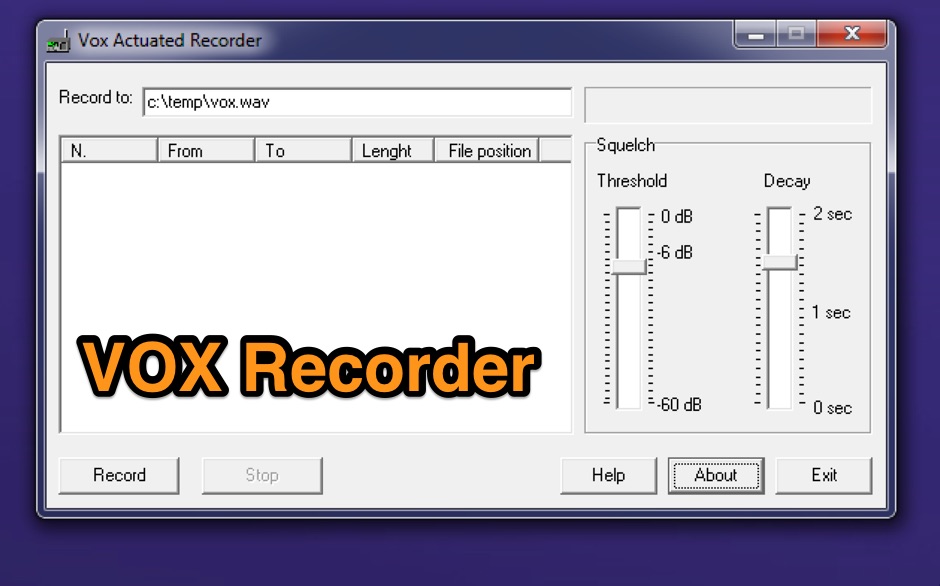 Vox Recorder is a specialized Windows utility designed for amateur radio operators, and radio listeners particularly those who use radio scanners. This software allows users to record audio from various sources, but it only activates when an audio signal is detected. This feature is particularly useful for avoiding the capture of silence or background noise, which can be common in radio scanning. By focusing on the audio signals, users can create cleaner recordings that are more relevant to their interests. The utility is user-friendly and tailored for hobbyists who want to document their radio listening experiences without the hassle of editing out silence later. Vox Recorder is an excellent tool for anyone involved in amateur radio, as it streamlines the recording process and enhances the overall experience of monitoring radio frequencies. Whether for personal use or for sharing with fellow enthusiasts, Vox Recorder helps ensure that every important transmission is captured effectively.
 -
 The Pfeiffer Maltese Quad Antenna System presents a unique approach to traditional quad antennas by utilizing a linear loading technique. This method effectively reduces the overall size of the antenna while maintaining its performance capabilities. Designed by Andrew Pfeiffer, the antenna's configuration resembles a Maltese cross, which not only enhances its structural integrity but also allows it to withstand challenging environmental conditions. This system is adaptable, offering various configurations from a 4-spreader Maltese Quad to a 16-spreader Maltese Quadruple-Cross, making it suitable for operators looking to optimize their setup without sacrificing efficiency. This antenna system is particularly versatile, covering multiple bands including 40, 20, 17, 12, and 10 meters. The design focuses on minimizing the physical footprint while ensuring effective signal transmission and reception. Amateur radio operators can benefit from the detailed plans available in the accompanying PDF, which outlines the construction process and specifications. Whether you're a seasoned DXer or a newcomer to the hobby, the Pfeiffer Maltese Quad Antenna System offers a practical solution for enhancing your station's capabilities.
 -
 This resource provides access to the 59+ software collection, specifically highlighting the **59+ CW** module. The software enables the generation of Morse code signals for transmission through a COM port to a transceiver, or for audio output via a computer speaker, facilitating both keying and listening practice. Users can customize various parameters, including CW speed, tone frequency, dash/dot ratios, and PTT line delay, alongside defining keyboard shortcuts for common QSO fields such as callsign, QTH, name, and RST. The collection also includes the 59+ Logbook, which operates smoothly on Windows XP according to testing notes, though the CW application experienced startup issues on the same OS. The software was originally designed for older Windows operating systems, specifically Windows 95, 98, ME, and 2000. It is noted that the original idealog.net site is no longer active, and development for the 59+ suite appears to be discontinued. Analyzer and converter modules within the collection require registration and do not function in trial mode.
 -
 Monitoring shortwave broadcast stations effectively requires accurate schedule information to identify transmissions. This online utility offers a straightforward, graphical interface designed to search for and display current shortwave radio broadcasting schedules. Users can precisely filter results by frequency, specific language, broadcaster, time of day, and even by shortwave band, which simplifies the process of pinpointing desired content. The database, last updated on March 26, 2023, details station callsigns (e.g., BBC), start and end times in UTC, days of the week, broadcast language, transmitter power in kilowatts, and azimuth. Crucially, it includes the precise geographical coordinates of transmitter sites, such as Woofferton in the UK or Al Seela in Oman. This data is invaluable for predicting signal paths and optimizing antenna direction for improved reception, a key consideration for serious SWLs. For instance, a search for BBC English broadcasts at 21:04 GMT quickly reveals multiple active frequencies like 17780 kHz from Woofferton, offering a clear overview of current transmissions. The tool processes queries rapidly, returning results within seconds, demonstrating its efficiency for broadcast listening enthusiasts seeking timely information.
 -
 DIY Basic Electronic Theory, Basic Antenna Theory with Antennas built from common materials. What does SWR really mean. Baluns from transmission line.
 -
 Demonstrates the construction and on-air performance of the _NB6Zep_ antenna, a modified 20-meter Extended Double Zepp design optimized for multi-band operation from 40 through 10 meters. The resource covers basic design principles, including dimensions of 66 feet horizontal and 5 feet vertical elements, and specifies open ladder line or TV twin lead for the transmission line. It details material selection for low-cost wire antenna construction, such as 18 AWG wire for the legs and ceramic or plastic insulators, along with practical tips for soldering connections and insulating against moisture. The author, NB6Z, shares insights from extensive _EZNEC_ modeling to optimize the antenna's total length for a 40-meter half-wave dipole footprint and feed line length for direct tuner connection. The article presents field results, including successful _PSK31_ contacts from Oregon to the East Coast on 40 and 30 meters with 50 watts, even at a low height of 6 feet. It provides detailed performance characteristics for each band, noting the _NB6Zep_'s highest gain (over 3 dB) and sharp, medium-angle lobes on 20 meters, which yielded strong DX reports to locations like Korea, Japan, and Argentina. For 17 and 15 meters, it describes a butterfly-like pattern with broad lobes, while 12 and 10 meters exhibit narrow, directional lobes in an "X" configuration. The author also shares personal experiences operating successfully for over a decade in an antenna-restricted environment using the NB6Zep and other stealth wire antennas.
 -
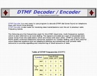 A very easy to use program to decode DTMF dial tones found on telephone lines with touch tone phones. The DTMF Decoder is also used for receiving data transmissions over the air in amateur radio frequency bands.
 -
 CWLab02 demonstrates a Windows-based software solution for Morse code enthusiasts, enabling both CW and CCW (Computer-Generated CW) sending and receiving within a single, integrated window. The program incorporates an improved CW interface, aiming to simplify the process of decoding and generating Morse code signals. It provides a straightforward method for hams to practice their CW skills or integrate computer-generated code into their operations, supporting real-time interaction with Morse code transmissions. The software's design focuses on ease of use for CCW operations, allowing operators to quickly generate and transmit code. While specific technical details on its decoding algorithms or WPM range are not provided, the emphasis on an "improved CW" suggests refinements in its signal processing capabilities. The ability to send and receive in the same window streamlines the user experience, offering a practical tool for training, casual QSOs, or integrating into a digital shack setup.
 -
 Dipole, Yagi, Vertical, Cubic quad, Log periodic, J-pole, coil, and transmission line design package for the Macintosh
 -
 Real 4:1 Transmission Line Balun with Balanced Load
 -
 The "EZ-Tuner" is a homebrew automatic legal-limit antenna tuner that covers all amateur HF bands from 160-10 meters. Using a T-network design and controlled by a BASIC Stamp BS2sx microcontroller, the EZ-Tuner will match at least a 16:1 VSWR for either unbalanced or balanced transmission lines.
 -
 Excel spreasheet that calculate virtually every transmission line parameter that one may need. Include Length conversions, Reactance and Length of Stubs
 -
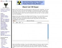 The **Black Cat CW Keyer** is a macOS application designed for amateur radio operators to transmit Morse code directly from their computer. It provides functionality for typing text to be sent, either immediately or buffered, and allows for the creation and transmission of pre-defined messages via single-key shortcuts. This software addresses the need for a flexible and accessible CW keying solution, particularly for Mac users who might find fewer dedicated ham radio applications compared to other operating systems. It integrates basic text-to-CW conversion, offering a straightforward interface for generating Morse code signals. Operators can utilize the Black Cat CW Keyer for various CW activities, including casual QSOs, contesting, or beacon operation. Its ability to buffer text allows for smoother transmission, while the single-key macro feature streamlines repetitive message sending, such as CQ calls or contest exchanges. While specific comparisons to other CW keying software are not detailed, its macOS focus provides a niche solution for Apple users. The program's utility lies in its direct approach to computer-based CW transmission, making it a practical tool for those seeking a dedicated **CW keyer** on the Macintosh platform.
 -
 This article proposes a lossy transmission line model of a practical Guanella 1:1 balun that is effective for all frequencies within and immediately adjacent to the pass band
 -
 The document details the optimization and construction of the _Maria Maluca_ antenna, a compact 6-band (20m-6m) directional beam. It presents a comparative analysis of shortwave antenna principles, highlighting the efficiency gains achieved by using an open feeder line and tuner as a resonant unit, contrasting this with the losses associated with traps or capacitive loads in multiband antennas. The resource specifically revisits an older South American 2-element design for 10, 15, and 20 meters, applying modern NEC-based software to develop a six-band version. Performance data is meticulously tabulated, showing impedance, free space gain, gain at 12m height, elevation angle, and front-to-back (F/B) ratio for each band from 20m through 6m. For instance, on 15m, the antenna achieves 5.1 dBd free space gain and 13.72 dB F/B ratio. The construction section provides practical guidance on element assembly using aluminum pipes and hose clamps, detailing the use of a heavy-duty glass fiber reinforced polyamide rod for electrical separation and bending strength. It also specifies the use of 450-ohm _Wireman_ line CQ 552 for the transmission line. The document includes diagrams for rod fixing, an air-wound balun, and a vertical elevation diagram for the 15m band, illustrating its DX qualification. It also discusses the antenna's suitability for portable and expedition operations, noting its compact transport dimensions (max 1.50m length, 12 lb weight) and quick assembly time (under 15 minutes). The author, Dipl.Ing. Helmut Oeller, DC6NY, is identified as a source for material kits.
 -
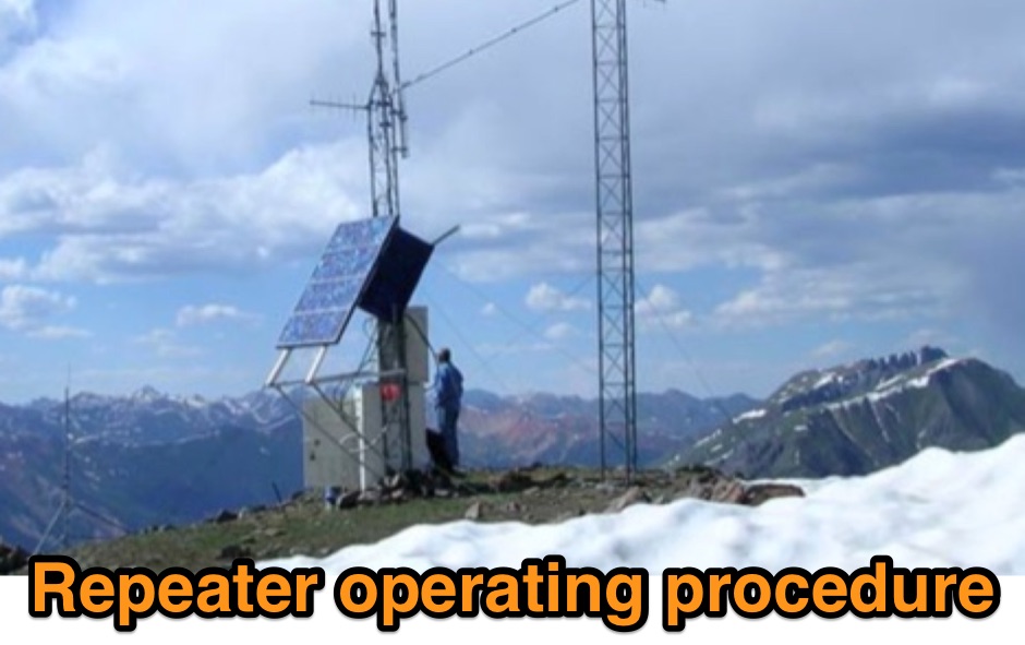 Outlines recommended operating procedures for amateur radio repeaters, detailing best practices for general on-air conduct. It emphasizes using simplex when possible, monitoring the frequency before transmitting, and maintaining concise, thoughtful transmissions to avoid monopolizing the repeater. The resource also stresses the importance of legal identification, such as the Canadian requirement at the beginning and end of a contact and every thirty minutes of operation. Furthermore, the article provides specific instructions for **autopatch** operation, including access codes and the necessity of brief calls, while cautioning against misuse for long-distance calls or commercial purposes. It highlights the financial support expected from regular users to maintain repeater infrastructure. Finally, the guide differentiates between permanently linked repeaters, which offer extended coverage, and **code access linked repeaters**, explaining the sequence of identification and code entry required to establish and terminate links for broader communication.
 -
 The project outlines the process for constructing a low-power FM broadcast transmitter using a Raspberry Pi Zero, a simple wire antenna, and battery power. It details the software installation steps for PiFM and MPG123, essential for generating and transmitting audio. The resource provides instructions for configuring the Raspberry Pi to broadcast FM signals, including command-line operations for initiating transmission and playing audio files. It specifically focuses on the Raspberry Pi Zero's capabilities for this application, highlighting its cost-effectiveness and minimal hardware requirements. The content presents a practical, hands-on approach to creating a basic FM transmitter, suitable for short-range, experimental broadcasting. It includes guidance on testing the FM output and ensuring proper operation of the software components. The project emphasizes the use of readily available components and open-source software to achieve functional RF output.
 -
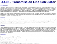
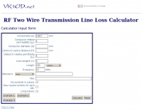 This calculator computes the matched line loss for a transmission line using a model calibrated from data for the transmission line types built in to the calculator. It also gives an estimate of the mismatched loss if the mismatch is specified.
 -
 Presents a detailed construction guide for a **Quadrifilar Helix Antenna** (QHA) optimized for 137 MHz, specifically for receiving weather satellite transmissions. The resource outlines the author's experience building previous QHA designs, highlighting challenges with tuning and nulls, and then focuses on a refined design by John Boyer, documented by Steve Blackmore, which proved easier to build and yielded superior reception. The guide provides precise element dimensions, including 1.5m of 32mm PVC pipe for the mast and 8mm soft copper tubing for the helix elements. It specifies lengths for horizontal tubes (190mm, 90mm) and helix elements (903mm, 1002mm), along with instructions for drilling, assembly, and forming a **balun** by wrapping RG58 coax around the mast. The text emphasizes critical steps like ensuring elements are square and twisting in the correct direction to avoid phase issues. It includes references to original QST articles by Buck Ruperto (W3KH) and the WxSat program for decoding satellite transmissions, contextualizing the antenna's purpose. The article concludes with a sample NOAA 12 image from September 1998, demonstrating the antenna's reception capabilities.
 -
 Demonstrates the design and construction of a 9-element Yagi antenna for the **70 cm band** (432 MHz), based on the DK7ZB concept. The resource details EZNEC+ calculations for a single antenna, providing gain, sidelobe suppression, and front-to-back ratio figures. It also presents a comprehensive analysis of stacking two such antennas, including optimal stacking distance (1000 mm) and the resulting performance enhancements for the stacked array, such as an increased gain of 17.03 dBi. The article includes detailed drawings, wire file dimensions in millimeters, and azimuth/elevation plots for both single and stacked configurations. Practical construction steps are documented with original photographs, illustrating element mounting, the **28 Ohm matching system** using two quarter-wave 75 Ohm transmission lines, and the critical N-connector wiring. It also covers the iterative process of fine-tuning the driven element length to achieve a return loss of 20 dB, validating the EZNEC+ simulation results with actual measurements.
 -
 SimSmith is a highly interactive, real time Smith chart graphing program. Circuits are constructed using drag-n-drop. Load files can be imported from the EZNEC and CocoaNEC antenna simulation software and from the AIM4170 and miniVNApro antenna analyzers. Circuits and load files can be of any size. Key Features: SimSmith is one of the few Smith chart packages which models transmission line losses. SimSmith also allows the description of circuit elements using algebraic equations. SimSmith has only one screen and allows the screen to be resized to increase workspace or readability.
 -
 Unix or linux programme atlc calculates the impedance of electrical transmission lines of totally arbitrary cross section.
 -
 Accurately determining an antenna's feedpoint impedance is crucial for optimal performance, especially when experimenting with new designs or making adjustments. While SWR meters provide basic information, a full complex impedance measurement reveals the resistive and reactive components, which are essential for proper matching. Modern antenna analyzers, like the _Palstar ZM30_ or MFJ259B, simplify this task, but measurements taken through a transmission line require careful interpretation due to impedance transformation. This resource details a calibration method to precisely account for the effects of the feedline. It explains how a transmission line can significantly alter the measured impedance, illustrating this phenomenon with a Smith Chart example where an 80m antenna's [22 + j6] Ohms feedpoint impedance transforms to [82 + j45] Ohms after a 10m line. The guide demonstrates using a transmission line calculator applet, such as the one by W9CF, to reverse this transformation. It outlines the process of calibrating a specific length of RG174 coax, showing how an initial 26ft estimate was refined to **25.85ft** to accurately predict a known 22 Ohm load, significantly improving accuracy over uncalibrated results.
 -

-
 A Smith charting program. You can enter either discrete components or transmission lines, see the results on screen and/or generate Postscript output. Component values can be changed numerically or using scrollbars.
 -
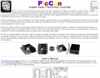 Hidden transmitter hunting, often called fox hunting or Amateur Radio Direction Finding (_ARDF_), presents a unique challenge for radio amateurs. This resource details the _PicCon_ controller, a specialized device designed to automate the transmission of signals for such events. It integrates with a standard radio transceiver, functioning similarly to a packet radio TNC, by controlling the Push-To-Talk (PTT) line and injecting audio tones or modulated CW Morse code into the microphone input. The _PicCon_ unit is field-programmable using DTMF tones received via the radio, storing all settings in EEPROM for power-off retention. Its compact design and low power consumption (a few milliamps from a 7-35VDC source) make it suitable for remote deployment. An onboard LED indicates operational status, and a push-button allows manual start/stop of transmissions without DTMF. Typically supplied as a kit, _PicCon_ includes a PCB, components, and a comprehensive manual (available in HTML, RTF, and PDF formats). The kit provides a six-conductor interface cable, but users must supply radio and power plugs due to varied configurations. Byon, _N6BG_, developed this controller, which is available from the Byonics website.
 -
 Transmission Line Details. This utility program shows the impedance and SWR at both ends of a transmission line and the details of power loss in the line. It includes characteristics for over 40 built-in line types. You can modify these values to see how small changes affect the results or to specify custom lines. All program inputs may be changed directly or you can use spin buttons to make the changes. If you are using a moderately fast computer you can hold down a spinner and "watch the movie" on the charts as the results are recomputed. By AC6LA
 -
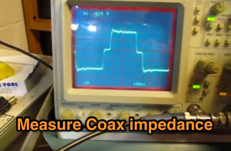 This video shows one way to use a scope and function generator to measure the length of a piece of coax transmission line as well as estimate its impedance
 -
 Understanding Common Mode and Differential Mode Currents on Transmission Lines by K9YC
 -
 Transmission Line equations for Windows. Written in Visual C++. This program provides the most comprehensive analysis of a transmission line by w9dmk
 -
 Don't neglect one of the most important parts of your station!
 -
 CWS ByteMark's Baluns (Balanced to Unbalanced) and Ununs (unbalanced to unbalanced) transformers are developed jointly with Dr. Jerry Sevick, W2FMI, who is known worldwide for his work on transmission line transformers
 -
 Demonstrates various practical amateur radio projects and technical discussions through video episodes. One episode details cutting and retuning a _1/4 wave shorted stub_ from 101.7 MHz to 107.5 MHz to safeguard a transmitter's driver stage, alongside insights into advanced _160-meter antenna systems_ like eight-circle arrays and beverage antennas. Another segment covers upgrading firmware on an _ATS-20+_ receiver using AverDudes for improved display and functionality, and a detailed guide on using D-Star DR mode on an _ICOM ID-52A_ for international repeater programming. Additional content includes a deep dive into _OpenHamClock_ as a potential replacement for the HamClock project, updates on _Raspberry Pi 5_ running Trixie OS, and a review of the Choyong LC90 Internet radio with AI integration. The series also features "Ham College" episodes, which meticulously prepare viewers for the Technician Exam by covering topics such as antenna and transmission line measurements, SWR interpretation, and the functions of basic electronic components like rectifiers, relays, and transistors. Practical advice on coaxial cable characteristics, dummy loads, and proper soldering techniques is also provided.
 -
 Guglielmo Marconi's foundational contributions to wireless communication began in 1894, inspired by Heinrich Hertz's discovery of radio waves in 1888. His initial experiments at his family home near Bologna quickly demonstrated signal transmission beyond line-of-sight, achieving distances up to **two miles** within a year. Marconi secured a patent in 1896, subsequently gaining interest from the British Admiralty after disinterest from the Italian government. By 1899, Marconi's system facilitated transmissions across the Bristol Channel (nine miles) and the English Channel (31 miles). A pivotal moment occurred in 1901 with the successful _transatlantic transmission_, defying the prevailing belief that Earth's curvature would limit practical range to approximately 200 miles. This achievement catalyzed the rapid development of the wireless industry. Marconi continued refining his inventions and, in 1909, shared the _Nobel Prize_ in physics with Karl Ferdinand Braun for their advancements in radio technology.
 -
 Radio wave propagation, Principles of transmission lines, Antennas
 -
 Millimeterwave/Microwave transmission lines and components, Cryogenic temperature application transmission cables and systems, Permittivity(Dielectric rate) and Permeabillity measurement systems, Antennas, Radar systems
 -
 Anderson Power Products specializes in high-current interconnect solutions, featuring products like the _Industrial Battery Connector_ (IBC) DIN-style connector for advanced battery charging applications. Their product line includes the SBS®XPRO connector, designed with three power contacts and eight signaling contacts, suitable for battery-powered equipment in harsh environments. The new Saf-D-Grid® Max connector supports up to **55A** and 600V, providing high power density in a C19 footprint, and is UL-rated for disconnect up to **40A**. They also offer IP68-rated SBS®X-75A connectors, engineered for waterproof high power and signal transmission. The company provides pre-crimped cable assemblies, simplifying proper contact maintenance between cables and connectors. Anderson Power Products serves diverse sectors including material handling, electric vehicles, telecom, office equipment, and power management, emphasizing reliable and rugged connector designs. Technical documentation and a comprehensive power connector catalog are available for detailed product specifications.
 -
 Linear Amp UK specializes in the design and production of high-quality linear amplifiers, offering models for HF, VHF, and UHF amateur and commercial applications. The company emphasizes nearly 30 years of experience in crafting each unit, ensuring robust performance and longevity. Their product line includes amplifiers engineered for a 100% duty cycle, promoting continuous and reliable operation across various modes. The amplifiers feature solid, dependable designs, ensuring quiet and effortless performance during transmission. Each unit is hand-built to stringent standards, reflecting a commitment to durability and operational stability. All products are CE approved, confirming compliance with European safety and environmental directives, and come with a standard two-year warranty, providing assurance to operators. Key specifications often include coverage for 1.8-30MHz (WARC bands), 50MHz, 70MHz, and 144MHz, utilizing tubes such as 811, 572, 811A, 572B, GS35, GS35B, 8877, 3CX1500, and _3CX1500A7_ in their designs.
 -

-
 An Energy Analysis at an Impedance Discontinuity in an RF Transmission Line
 -
 How to measure the characteristic impedance of a unknown transmission line using MiniVNA
 -
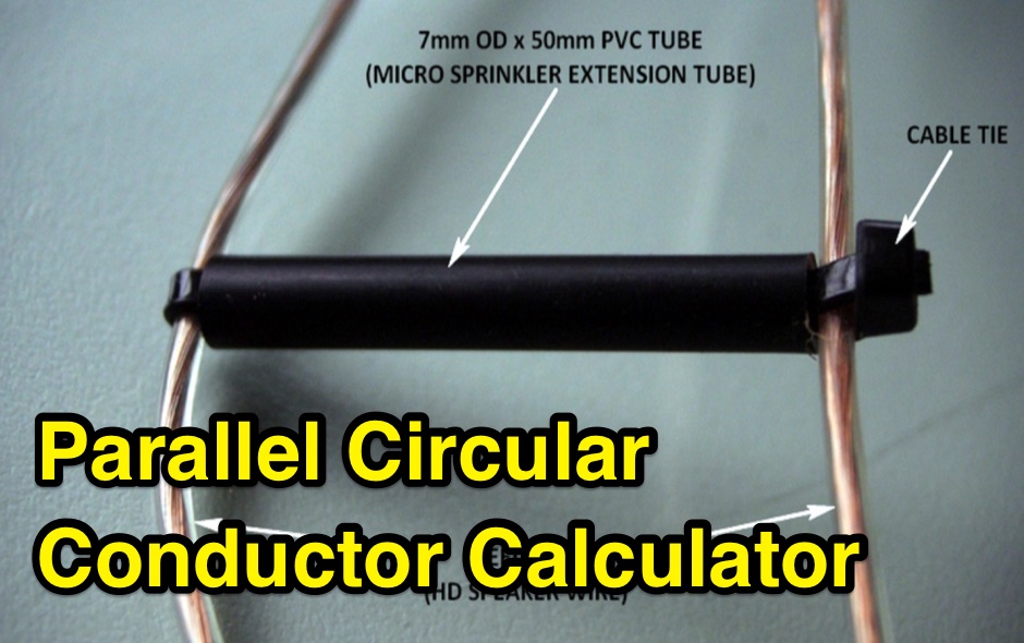 Design a parallel circular wire balanced transmission line with this online calculator. This calculator is a tool for designing balanced transmission lines with a specific desired characteristic impedance Zc and made of parallel circular conductors of a given diameter d.
 -
 Broadband over power lines (BPL) is a technique for transmission of high speed data (broadband Internet) over powerlines. Access BPL technology injects radio frequency energy into powerlines which were not designed for transmission of radio frequency energy, and leak substantial energy that causes interference to radiocommunications service
 -
 How do two-wire reversible direction Beverages work, an excellent document that explains fundamentals of beverage antennas. This article details the design and performance of a reversible beverage antenna. Leveraging orthogonality between common mode and differential mode currents on a 2-wire line, this antenna facilitates independent reception from both ends. While common mode signals arrive and are summed on a transformer's secondary for common mode reception, differential mode signals induce anti-phase currents, providing individual reception. Various measurements explore impedance, transmission loss, and F/B ratio, highlighting the antenna's effectiveness and areas for improvement. Notably, increasing the antenna's height significantly improved performance.
 -
 Demonstrates the _RoMac Automatic CW Identifier 2012_ software, a Windows application designed to automate station identification and provide a tuning pulser. It can send CW identification via a sound card's audio output or by keying a radio's manual CW jack using a serial port's DTR line. The software also supports CAT commands for various Kenwood, Yaesu, Flex, and Elecraft radios, enabling automatic mode and frequency changes for ID transmission. It integrates with USB audio-capable radios like the Icom 7300 and Yaesu FT-991, simplifying connectivity with a single USB cable. The application features a fully programmable interface, adjustable CW speed from **5 to 35 WPM**, and ID intervals from **5 to 30 minutes**. The integrated "Pulse Tuner" function allows for safe amplifier and antenna tuner adjustments by sending short audio tones or rapid CW keying, with an adjustable duty cycle from 1% to 100%. It offers compatibility with a wide range of transceivers and amplifiers, and a schematic for a basic sound card interface is included for users without existing setups.
 -
 The IFR-100 PMR446 radio, developed by ICIT Co., Ltd., incorporates a unique _private speaker_ function. This feature enables users to receive communications discreetly, preventing audio from being broadcast aloud from the radio's internal speaker. Instead, the operator can hear transmissions exclusively through a connected earpiece or similar accessory, facilitating private talk mode operations. ICIT Co., Ltd. positions itself as a primary developer and manufacturer of PMR446 equipment within Korea. Their product line emphasizes innovative features designed to enhance user privacy and operational flexibility in short-range, license-free radio communications. The company's focus is on delivering specialized two-way radio solutions. The resource highlights the company's manufacturing capabilities and its commitment to developing distinct functionalities for the PMR446 market. It underscores their role in providing specific communication tools for users requiring secure and private audio reception.
 -
 A Linux Smith charting program. You can enter either discrete components or transmission lines, see the results on screen and/or generate Postscript output. Component values can be changed numerically or using scrollbar
 -
 The collinear antenna, or Marconi-Franklin antenna, is an omnidirectional, high-gain antenna composed of in-phase half-wave dipoles aligned vertically. By using quarter-wave transmission line segments, it maximizes gain at a low horizon angle, outperforming a half-wave dipole. Adding segments increases gain but narrows bandwidth. A popular DIY version, the CoCo antenna, uses half-wave coaxial cable segments connected by non-radiating transmission lines. Built with stable velocity factor cables, a matching quarter-wave sleeve balun, and ferrite rings for attenuation, the antenna achieves performance comparable to commercial models.
 -
 A synthesized 2.3 GHz Amateur Television (ATV) transmitter design, conceived by Ian G6TVJ, is presented, targeting broadcast-quality video performance on the 13cm band and extending up to 2.6 GHz. The core of the design utilizes a commercial Z-comm Voltage Controlled Oscillator (VCO) that tunes from 2.2-2.7 GHz, providing a +10 dBm output and simplifying RF alignment. This VCO's stability, originally intended for narrowband applications, readily accepts high-frequency video modulation, contributing to the transmitter's robust performance. The exciter stage, incorporating a Mini Circuits VNA 25 MMIC amplifier, boosts the signal to +16dBm, while a Plessey SP4982 prescaler divides the output frequency for the synthesizer. The synthesizer employs a Motorola MC145151 CMOS parallel IC, favored over the common Plessey SP5060 for its superior video modulation characteristics and ease of programming without microprocessors. This choice addresses issues like LF tilt and distorted field syncs often seen with SP5060 designs, particularly when operating through repeaters or over long distances. The MC145151 divides the signal further, enabling precise frequency stepping, with programming handled by EPROMs for channel selection and LED display. The loop filter network, critical for video integrity, was developed through experimentation to prevent the PLL from reacting to video modulation, ensuring a clean transmitted picture. The transmitter incorporates a Down East Microwave commercial power amplifier module, delivering approximately 1.6W output, driven by the exciter through a 3dB attenuator. Construction involves surface-mount SHF components on micro-strip lines etched onto double-sided fiberglass board, housed within a tinplate box. The design boasts no AC coupling in the video path, preserving low-frequency response, a common failing in other ATV transmitters. Performance tests with a 50Hz square wave revealed no LF distortion, and a calibrated "Pulse & Bar" signal showed a near 100% HF response, demonstrating its capability for high-quality ATV transmissions.