Search results
Query: 6 meters band
Links: 610 | Categories: 5
-
 Top Loaded Vertical Antenna 3,5 MHz 80m and a 14 MHz Trap for the 20m band. The weight of this portable vertical antenna is less than 1 kg, including the ground network. The weight of the telescopic fiberglass fishing rod is another 1kg. The rod expands from 1.5 meters to 8 meters.
 -
 Homemade receiver for 80 meters band. The receiver works very well (in fact better than some of its successors), especially the AGC makes listening to 80m QSOs a real pleasure. Sensitivity is not cutting-edge, but on a full-size short-wave antenna it is by fare sensitive enough.
 -
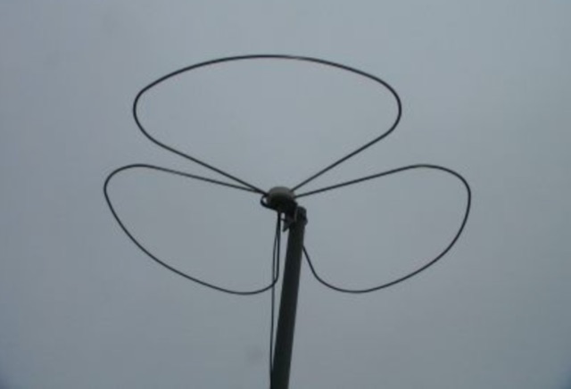
 An Hentenna project for the six meters band. The standard size of standard hentenna is width 1/6 wavelength x height 1/2. The antenna build in this project is a full wavelenght antenna for the 50 MHz providing a 6.8 dbi gain.
 -
 Basically, this antenna is a 23-foot wire fed through a 4:1 un-un transformer. This antenna can be easily used in portable operation, for operating all bands from 40-10 meters.
 -
 A dual band vertical antenna for 160 and 80 meters band, on a 18m spiderbeam fiberglass pole. This vertical is a good compromise when you want good performance on these two low ham bands and don't have the space to install two seperate antennas.
 -
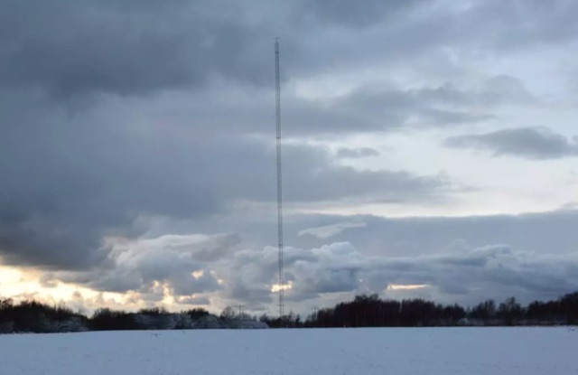
 DF0WD/DL4YHF's Longwave Overview details amateur radio operations on the 135.7 to 137.8 kHz segment in Germany. The author outlines the "inofficial" European band plan, specifying segments for QRSS, TX tests, beacons, conventional CW, and data modes. Early LF activities at DF0WD began with a 20-watt CW transmitter, later upgraded to a homemade linear transverter capable of 100 watts, driven by an Icom IC706 on 10.137 MHz. The station's antenna system includes a 200-meter wire, approximately 10 meters above ground, supported by football field light-masts. Despite its length, the antenna's efficiency is noted as very low due to the immense wavelength of about 2.2 km. The author's experience highlights the significant challenge of achieving effective radiated power (EIRP) on LF, estimating DF0WD's EIRP at around 80 milliwatts based on field strength measurements from PA0SE. DF0WD/DL4YHF has successfully worked numerous countries on 136 kHz CW, including DL, F, G, GI, GM, GU, GW, HB9, HB0, LX, OE, OH, OK, OM, ON, OZ, PA, and SM. The author also mentions ongoing efforts to log contacts with CT, EI, LA/LG, and to complete a two-way QSO with Italy, demonstrating persistent activity on this challenging band.
 -
 Four or Five turn one meter loop antenna for 80 and 160 meter band. This home made receive only antena can be assembled in a small place.
 -
 The ARRL's End-Fed Half-Wave (EFHW) Antenna Kit is an easy-to-build four-band antenna designed for 10, 15, 20, and 40 meters. Ideal for portable operations, it includes a 49:1 impedance transformer for compatibility with most transceivers. This project, detailed with step-by-step assembly instructions, involves creating a weatherproof enclosure and impedance matching network. The kit simplifies HF operations and supports multiple configurations, making it a versatile tool for amateur radio opertors.
 -
 This page describes an entirely simple, One-Knob matchbox that will match this antenna efficiently on 40, 30 and 20m, using a simple circuit that can be switched between series-resonant and parallel-resonant with just one banana jumper
 -
 Spitfire Collinear Arrays for 160 meters band at UA2FW
 -
 This type of antenna is a popular antenna design as the performance is very good across the HF bands and requires little or no tuning. It’s a dipole fed off center with a 4:1 balun at the offset feed point. The antenna shown covers 80, 40, 20 and 10 meters. The formula can also be used to adjust the overall length to cover more or fewer bands and the resulting overall length. 160-10m, 80-10m or 40-10 meters depending on your available space. Other bands will require a tuner.
 -
 Building A Full-Wave Quad Loop Antenna for 6 Meters. This is an easy antenna to build and the materials cost about $15-20. It exhibits 1.8dB gain over a 1/2-wave dipole. Using an open-wire parallel feedline (commonly called ladder line) with an antenna tuner, it tunes up on the 10m band as a 5/8-wave loop as well
 -
 Getting Started on the Magic Band is a very exaustive article about operating the six meters band. It covers several aspects of operations, techniques, tips and guidelines on getting started on the six meters band.
 -
 Constructing a dual-band antenna for 40 and 20 meters often involves compromises in size or complexity. This resource presents a compact _open sleeve dipole_ design that addresses these challenges by using 450-ohm ladder line and folded elements to achieve a total length of approximately **17.17 meters**, significantly shorter than a full-size 40-meter dipole. The design leverages electromagnetic coupling, where a primary radiator handles the 40-meter band, and a second conductor resonates on 20 meters without direct electrical connection. This configuration eliminates the need for traditional traps, loading coils, or switching components, simplifying construction and reducing potential loss points. The antenna is fed with RG-58C/U coaxial cable, and a common-mode choke is recommended at the feed point to suppress sheath currents, ensuring a cleaner radiation pattern and minimizing RF in the shack. The design is well-suited for portable operations, field deployments, temporary installations, and restricted urban environments where space is a premium, offering solid performance on both HF bands.
 -
 A magnetic loop antenna designed for 14 MHz. This kind of antennas is also known as STL, small transmitting loop and can be an excellent solution when you are not allowed to put antennas on your roof
 -
 A 60-foot available space, for example, might necessitate a shortened multiband dipole array to cover 80, 40, and 15 meters effectively. This resource details the construction of such an antenna, combining full-size and coil-loaded dipoles on a single feedline. It addresses the common challenge of fitting multiple HF bands into restricted physical footprints, providing practical guidance for hams with smaller backyards or portable operations. The core of the offering is an interactive calculator that determines required loading coil inductance and dipole lengths for various amateur bands from 160m to 10m. Users input their available space, and the tool provides dimensions, coil turns, and an efficiency rating (Good or Fair) based on the antenna's electrical length relative to a quarter-wavelength. It also suggests suitable _PVC_ pipe diameters for coil forms. The article further illustrates a center feed-point assembly using an 18-inch section of 2-inch _PVC_ pipe, detailing eye-bolt spacing and coaxial connector installation. It emphasizes the importance of adequate spacing between parallel dipoles and offers customization options for the feed-point, including the addition of a _Balun_ for improved feedline isolation.
 -
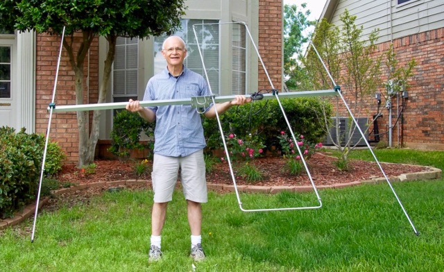
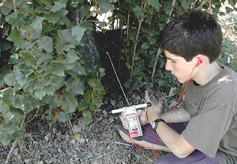 If your club holds only two-meter ARDF events, you are missing half the fun. There is another international foxhunting band, too.
 -
 A dedicaed vertical antenna for 80 meters band based on a 40 meter vertical experiment
 -
 A vertical antenna for 160 meters band based on the K6MM vertical with some enhancements and modifications on the main capacitance hat
 -
 WebSDR Pardinho SP Brazil providing access to HF bands 160 80 40 20 15 11 meters bands.
 -
 With this antenna the coverage is 80,40,20,15 and 10 meter band without any antenna tuner and the average SWR is below 1.2 on phone bands. The total antenna lenght is about 23 meters , with one 20.4 meters long segment from the 1:49 transformer to the 110uh coil and about 2.2 meters long segment from the coil to the insulator.
 -
 This 10 meter antenna is right out of the ARRL Antenna Book. There are 5 elements on a 24 feet boom and it performs well from 28.0 to 28.9 MHz.
 -
 This PDF guide provides detailed instructions and diagrams for constructing a fan dipole antenna, a popular choice among hams for multiband operations. The guide covers the design, materials needed, and installation process, offering step-by-step guidance to help hams set up an effective antenna system for their radio operations.
 -
 Experimenting with capacitive antennas for 40 and 80 meters band. A very space-saving antenna with good receivings caracteristics
 -
 Jeri Ellsworthhas started a video series devoted to building a magnetic loop antenna for the 160- and 80-meter bands. The first video, included after the break, is an overview of the rationale behind a magnetic loop
 -
 Vertical end fed antenna used for portable operations. The antenna will work on 80 with acceptable results, it will work fine on 40m, and it will be a good deal better than a normal 1/4 wave GP on 20, 17, 15 meters.
 -
 This small dual band UHF VHF directional antenna is good choice for portable operations. This antenna is composed by a moxon antenna for the two meters band and it includes two parastatic elements for 70 cm band.
 -
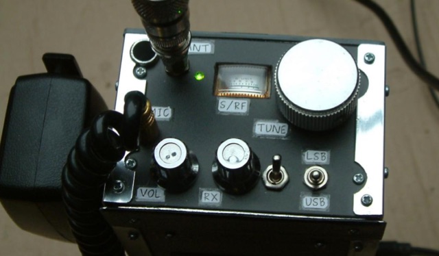
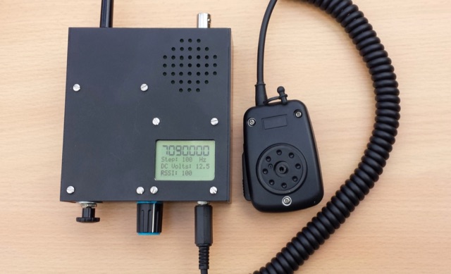 A home made portable QRP transceiver designed to work on 40 or 80 meters SSB band.
 -
 Hy-Gain TH3jr Tri-band HF 3 Element Beam Covers 10, 15 and 20 Meters assembly instruction manual
 -
 An omnidirectional horizontal polarization antenna for 2 meters band in Italian
 -
 A 30 cm antenna for the six meters band in japanese
 -
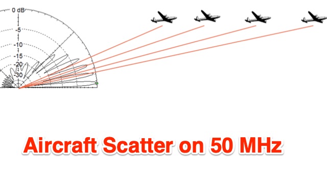 Aircraft scatter is easily seen on the spectrogram window of digital communication apps, when you know what to look for. Examples of real aircraft scatter usage on six meters band
 -
 A j-pole antenna plan with drawings and dimensions that can help you on building your own j-pole antenna for the six meters band
 -
 20W portable handheld SSB transceiver for 20 meters band
 -
 The longest element has a total length of 14m and has a boom length of 5.5 meters featuring a total bandwith of 166 kHz
 -
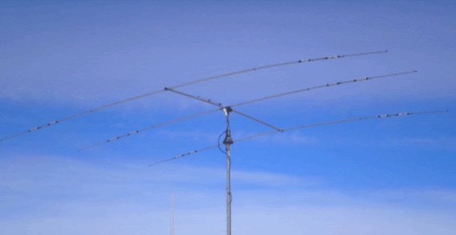 An analysis and performance improvement of the HyGain TH3JR on the 20 meters band.
 -
 Experimentin wire antennas on top band using several type of aerials. This includes a 40 to 160 meters EndFed Half Wave kite antennas and 160m/80m loaded vertical antenna.
 -
 Operating marine mobile with antennas for 15-17-20 meters band.
 -
 This article explores the evolution of antenna choices for DXpeditions, focusing on the shift from mono-band VDAs to a multi-band solution. It details the design and construction of a lightweight, versatile 20-17-15m VDA, utilizing readily available materials like fishing rods and IKEA breadboards. The author discusses challenges, adjustments, and offers guidance for replication.
 -
 This article introduces an Arduino-based QRP CW Transceiver designed for lower HF bands. The journey begins with the Wotduino, evolving from a keyer to a multi-mode beacon. The development includes a QRP transmitter and culminates in a receiver inspired by Roy Lewallen design. The transceiver, controlled through a control bus features a signal path, modulation, filtering, and adjustable frequency settings. Despite initial testing intentions, successful QSOs on 80 and 40 meters showcase its functional capabilities.
 -
 Building an End-Fed Half-Wave (EFHW) antenna from a kit, as detailed by Frank Bontenbal, PA2DKW, with process photos by Bob Inderbitzen, NQ1R, offers a practical approach for hams. This specific kit, a collaboration between ARRL and HF Kits, targets 10, 15, 20, and 40 meters, making it a versatile option for HF operations. Unlike a center-fed dipole, the EFHW is a half-wavelength antenna fed at one end, which simplifies deployment, particularly for portable use. The construction guide meticulously outlines the assembly of the 49:1 impedance matching network, crucial for transforming the antenna's high impedance (around 2,500 Ohms) to a transceiver-friendly 50 Ohms. Steps include preparing the enclosure by drilling holes for the coaxial connector and antenna connections, followed by the precise winding of enameled copper wire onto a toroid to create the transformer. The guide emphasizes careful insulation removal and soldering for reliable connections. Final assembly involves integrating a 100 pF capacitor for higher band compensation, soldering the transformer's primary and secondary sides, and conducting SWR tests with a 2K7 resistor or a half-wavelength wire. The document also provides examples of wire lengths for different bands, such as 16 feet for 10 meters or 66 feet for 40 meters, demonstrating the transformer's adaptability for various half-wavelength configurations.
 -
 A homebrew 13 elements yagi antenna for two meters band. These project includes two model of the same antenna with a 6 and 7 meter boom length. Detailed pictures and nec files are available for download
 -
 Explains the fundamental purpose of a repeater, detailing how these automated relay stations overcome distance and terrain limitations for VHF/UHF communications. It traces the historical development from early Bell Telephone Labs "relay" stations in 1922 to Art Gentry, W6MEP's, pioneering K6MYK amateur radio repeater in the mid-1950s, which remains active today. The resource clarifies the distinction between simplex and duplex operation, including the unique function of a "parrot repeater" for single-frequency recording and playback. Delving into the internal workings, the guide breaks down a repeater into its core components: the antenna system, feedline (often _Heliax_ or hardline for minimal loss), duplexer, receiver, transmitter, and controller. It emphasizes the critical role of the duplexer in preventing receiver desensitization by isolating transmit and receive signals, even with distinct frequencies. The discussion highlights the importance of high-performance, durable antennas and low-loss feedlines, citing examples of equipment installed in the 1960s and 1970s that are still in perfect working order. Operating a repeater is also covered, with an explanation of frequency offset (e.g., the 600 kHz standard for 2 meters) and the function of _CTCSS_ (PL tone) for access. It outlines standard input/output offsets for various bands, from 6 meters to 23 centimeters, while noting regional variations. The guide also touches on features like autopatch and Digital Voice Recorders (DVRs), providing a solid foundation for understanding repeater technology and usage.
 -
 Listen to HF communications via the KiwiSDR online receiver located in Badgad IRAQ locator LM23fh. This web receiver is running a MLA 30+ antenna and can be tuned easily on all HF bands from 10 to 80 meters.
 -
 The antenna I built was inspired by a portable delta loop designed by Doug DeMaw, W1FB. Given that I constrained myself to a 50-foot roll of speak wire, I scaled my antenna for the 20M band. Using the formula, 1005 divided by the frequency in megahertz, I calculated a total length of 71 feet (21.6 meters) for the center of the 20M band.
 -
 Make your own dipole for 40 and 80 meters band, assembling standard product parts like 40 meter traps, the 1:1 balun and insulators
 -
 This antenna works on 17, 20, and 30 meters, with the best bandwidth on 20 meters. The bandwidth on 17 and 30 is quite small but usable. There is a 20 KHz bandwidth on 20 meters.
 -
 This project involves constructing a dual-band Moxon antenna, optimized for ham radio enthusiasts, with functionality on both the 10-meter and 6-meter bands. The antenna is designed to operate using a single 50-ohm feedpoint, acting as a mini-beam on 28 MHz (10 meters) and as a 2-element Yagi on 50 MHz (6 meters). Performance-wise, it offers a 4.0 dBd gain on 10 meters and 4.3 dBd on 6 meters, with impressive front-to-back ratios of 30 dB and 11 dB, respectively. Builders like Aleks (S54S) and Marcio (PY2OK) have successfully brought this design to life using the provided specifications. Aleks noted that bending the corners of the structure proved especially useful during assembly. The project comes with a detailed parts list, highlighting the use of aluminum tubes with different diameters and lengths to form essential components like the reflectors and radiators. For those looking to fine-tune the antenna, adjustments can be made by altering the length of certain parts that fit into larger tubes. The feeding system is equipped with a balun to accommodate different power levels, making the design versatile enough to handle outputs of either 300 watts or 1 kilowatt.
 -
 Build A Shortened 40 Meter Vertical antenna For POTA / SOTA Activations. A project for a portable wire antenna for 40 meters band suitable for POTA or SOTA operations.
 -
 This document details the construction of a multi-band end-fed antenna, suitable for situations with limited space for larger antennas. The design utilizes a 1:49 to 1:60 impedance transformer to match a half-wave wire antenna fed at one end. Compared to a traditional dipole, this antenna resembles a highly unbalanced Windom antenna with one very long leg and a virtual short leg. The design eliminates the need for radials but relies on the coax cable shield for grounding. The document recommends using at least 10 meters of coax and installing a common mode filter at the entry point to the shack for improved performance.