Search results
Query: HF
Links: 939 | Categories: 117
This query is too generic. Please try adding an additional term to focus your research.
Categories
- Radio Equipment > HF Vertical Antenna > Butternut HF2V
- Manufacturers > Antennas > HF
- Technical Reference > Amplifiers > HF Amplifiers
- Radio Equipment > HF Amplifiers
- Operating Modes > HF Operations
- Technical Reference > HF Radios
- Radio Equipment > HF Transceivers
- Radio Equipment > HF Vertical Antenna
- Radio Equipment > HF YAGI Antennas
- Technical Reference > Amplifiers > UHF Amplifiers
- Technical Reference > Amplifiers > VHF Amplifiers
- Shopping and Services > Antennas > VHF Antenna
- Technical Reference > VHF Radios
- Operating Modes > VHF UHF
- Antennas > VHF UHF
- Radio Equipment > VHF-UHF Amplifiers
- Radio Equipment > VHF-UHF Handhelds
- Radio Equipment > VHF-UHF Mobile
- Radio Equipment > HF Portable Antenna
- Manufacturers > Antennas > VHF UHF Microwave
- Radio Equipment > HF Amplifiers > Acom 1000
- Radio Equipment > HF Amplifiers > Acom 1010
- Operating Modes > Aircraft scatter
- Radio Equipment > HF Amplifiers > Alpha 8410
- Radio Equipment > HF Amplifiers > Alpha 87A
- Radio Equipment > HF Amplifiers > Alpha 9500
- Radio Equipment > HF Amplifiers > Ameritron AL-811
- Radio Equipment > HF Amplifiers > Ameritron AL-811H
- Radio Equipment > HF Amplifiers > Ameritron ALS-600
- Software > Beacon Monitoring
-
 MP3 and Wav files of some stations recorded on HF anc VHF bands by K9MU
 -
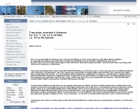 The resource details the construction of a multiband trap-style Inverted-V antenna designed for operation on 3.5 MHz, 7 MHz, 14 MHz, 21 MHz, and 28 MHz. It presents specific winding data for the traps, including the number of turns, wire gauge, and coil former dimensions, crucial for achieving resonance on the target bands. The document provides a parts list and a diagram illustrating the antenna's physical layout and trap placement. It outlines the process for building the traps using PVC pipe formers and specifies the required capacitor values for each trap. The design emphasizes a practical approach to achieving multiband operation with a single feedline, a common goal for HF operators with limited space. The document includes a table with antenna segment lengths for each band, allowing for precise replication of the design. It also offers insights into tuning and adjustment, ensuring the antenna performs optimally across the designated amateur radio bands.
 -
 Hi-Z Antennas offers specialized high-impedance receiving systems, primarily focusing on phased vertical arrays for HF reception. Their product line includes preamplifiers designed for shortened vertical antennas, featuring optimized 15dB gain and array-matched characteristics. These components are engineered to enhance weak signal reception and improve signal-to-noise ratio across the HF spectrum. The company provides controllers for managing multiple vertical elements in a phased array configuration, enabling directional reception patterns. These systems are particularly effective for mitigating local noise and interference, a common challenge in urban and suburban operating environments. Specific offerings include solutions for 160-meter and 80-meter bands, addressing the unique requirements of low-band DXing. Technical details often reference components like the 2N3866 transistor in preamp designs and discuss concepts such as out-of-band attenuation. The focus remains on optimizing receiving antenna performance through impedance matching and active amplification, rather than transmit capabilities.
 -
 Shelby amateur radio club's VHF emergency net is open to all within the repeater's coverage area. 146.880 and 147.345 are the repeater frequencies. Shelby Radio Club is the sponsor of the Shelby hamfest.
 -
 Using a PC with soundcard as a VLF receiver, how to use your PC as a receiver for narrow-band signals in the VLF radio spectrum by DL4YHF
 -
 This circuit came out of some work done for two antenna analysers
 -
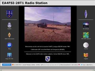 Description and simulation of two types of rhombic antennas, using the software 4Nec2: the simple bi-directional and the terminated directional rhombic antenna
 -
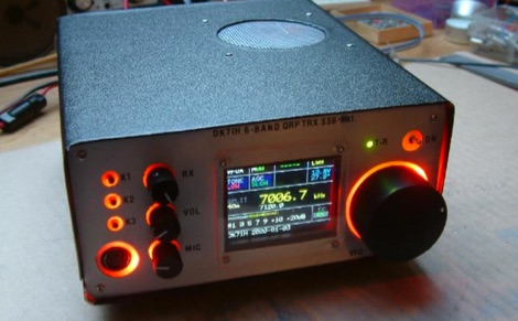 An SSB radio for the HF bands will be presented. Featuring 12 to 20 Watts of output power (depending on DC supply), full DDS frequency generation, covering 6 major frequency bands (1.8, 3.5, 7, 14, 21 and 28 MHz) within the short wave amateur radio spectrum. The rig also features colored LCD and front panel backlight.
 -
 Ten essential tips and truisms for understanding HF antenna: Non-resonant wire dipole antennas fed with open-wire line and an antenna tuner can function effectively as multiband antennas, as detailed in "The Classic Multiband Dipole Antenna" by WB8IMY in March 2004 QST. Coaxial cable, unlike balanced parallel-wire feed lines, can cause RF to travel on the outer shield braid, leading to RF feedback to the station; a 1:1 balun at the dipole center can mitigate this by isolating the unbalanced coaxial feed line. Antenna gain is achieved by shaping and directing RF energy, with beam antennas concentrating power in a specific direction, and wire antennas also exhibiting shaped radiation patterns. An antenna tuner's primary role is to match the transceiver's 50-ohm output to the antenna system's impedance, allowing modern transceivers to deliver full power. Wire antennas do not always require center feeding; end-fed long wires or off-center-fed dipoles (like the Windom) can be used, though they often necessitate an antenna tuner and a counterpoise or radial network. Dipole antennas do not need to be perfectly horizontal; their legs can be bent or inclined, which affects feed point impedance and may require SWR experimentation with coaxial feed. Vertical antennas shorter than a half wavelength require an efficient ground system, typically comprising elevated or buried radial wires, with more radials generally leading to better efficiency. A 1:1 SWR indicates an impedance match but does not guarantee antenna efficiency; an inefficient vertical antenna with a poor ground system can show a low SWR while wasting most RF as heat. Investing in high-quality, low-loss feed line, especially coaxial cable, is crucial for maximizing RF signal transfer and overall antenna system performance.
 -
 Hams have been putting stations in their cars since the Twenties. Today, there is great satisfaction in facing the challenge of installing a transceiver in our small cars and pick-ups, using somewhat inefficient antennas
 -
 Concentrating on VHF DX, Aurora, Meteorscatter, TEP, Sporadic E, EME, VHF DXpeditions. Daily updates.
 -
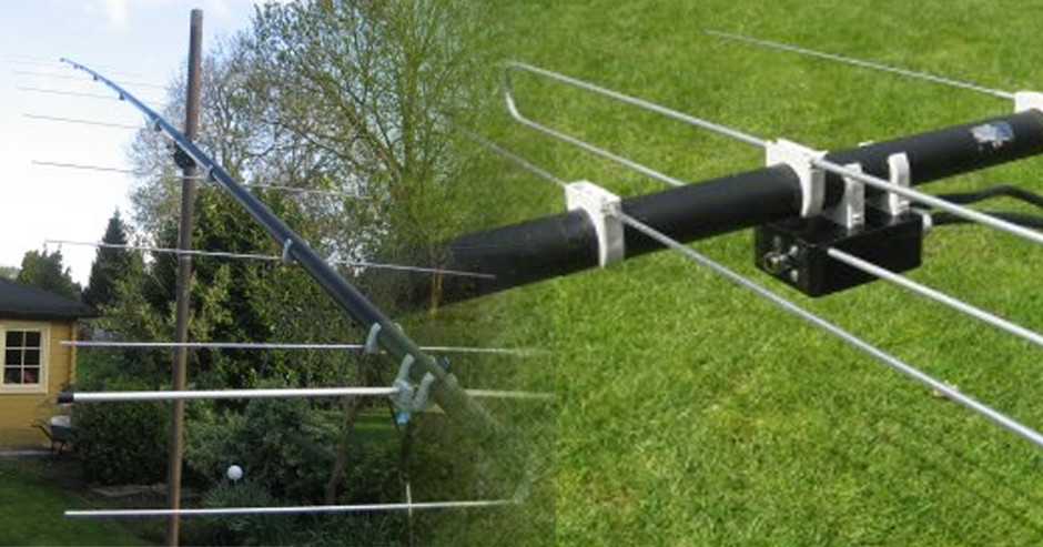 A ten element ultra-lightweight yagi beam antenna for 144 MHz based on YU7EF design concept
 -
 A 17 3/4-inch radiating element and 18 3/4-inch ground plane radials form the basis of this quarter-wave ground plane antenna for 2 meters FM. The design, attributed to AA1PG, utilizes a panel-mount SO-239 UHF connector and three lengths of #12 copper wire, with a total material cost estimated at $3.00. Construction involves soldering the elements directly to the SO-239, emphasizing thorough solder flow for robust connections. Recommended feedline includes _RG-8X_ for longer runs, with _RG-58_ acceptable for shorter lengths, cautioning against _RG-174_ for VHF applications due to high loss. The antenna is designed for elevated deployment, such as in trees or on roof gables, to maximize line-of-sight propagation. It aims to improve repeater access compared to typical rubber duck antennas, even with low power output.
 -
 Constructing a mobile HF antenna presents unique challenges, particularly when aiming for multiband operation and robust mechanical stability. This project details N1GY's adaptation of the KM4IE $20 antenna and the _Texas Bugcatcher_ design, focusing on practical build considerations and on-the-road performance. The author shares insights from winding coils on 2-inch PVC forms and integrating a salvaged fiberglass core from an old Hamstick-style antenna to enhance structural integrity, preventing potential failures from stress on PVC joints. N1GY's build includes a custom matching coil and a commercially sourced MFJ loading coil, carefully integrated into the design. The article provides specific tap settings for bands from 75 meters to 15 meters, achieving SWRs as low as **1.2:1** on 40 meters and **1.6:1** on 75 meters. Mechanical testing involved driving at speeds up to 70 MPH on Interstate routes, confirming the antenna's durability and the effectiveness of its PVC brace system. Further modifications address real-world usability, such as simplifying antenna removal for car washes. The ground strap was updated with a Power Pole connector, and the brace attachment to the luggage rack was converted to wing nuts, reducing removal time from 30 minutes to approximately _five minutes_. This iterative design process highlights practical solutions for mobile HF operation.
 -
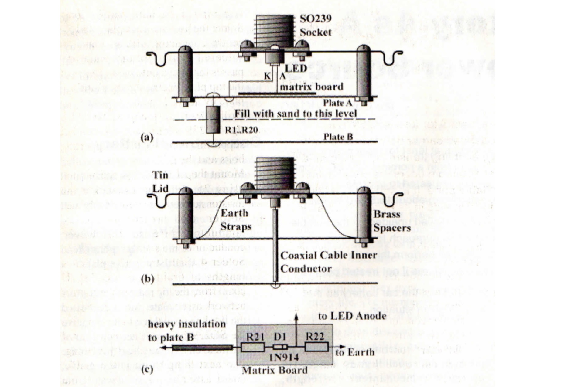 A handy piece of test equipment useful for HF bands, can absorb a 200W modulated carrier for almost 2 minutes. It is housed in a tin and part filled with dry sand that helps in power dissipation
 -
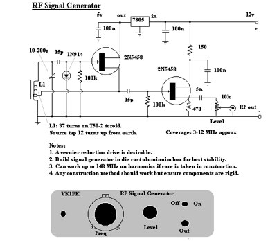 A home made project for a 3 to 12 MHz signal generator
 -
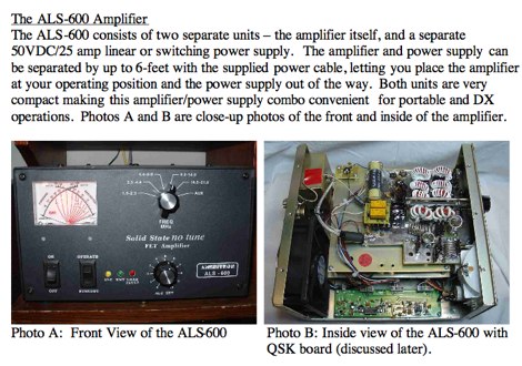 The Ameritron ALS-600 600-Watt HF Power Amplifier review by AD5X
 -
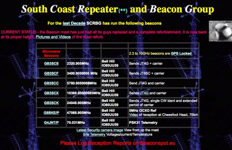 As used on the new GB3VHF 144.43MHz Beacon
 -
 Irish ham and Vhf radio info. Logs and maps worked, no excuses, this is mainly a VHF site
 -
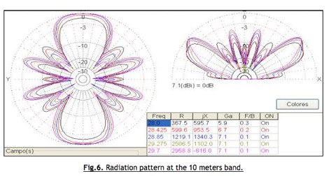 This article describes the design and simulation of a multiple dipole antenna for the HF band, using the software MMANA-GAL. The antenna will be designed to operate in the 10, 20, 40 and 80 m bands
 -
-
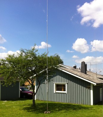 Assembling the Butternut HF9v HF vertical antenna
 -
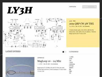 Pictures and project design of a crossband VHF UHF repeater by LY3H
 -
 Technical specification by Universal Radio
 -

-
 Presents the construction of a 2-meter **Skeleton Slot Yagi** stack, detailing the design process and practical considerations for VHF operation. The author shares insights from building and testing this antenna, emphasizing its performance characteristics for local and extended range contacts. The project outlines the specific dimensions and materials used, providing a clear path for other radio amateurs to replicate or adapt the design for their own stations. The resource covers the unique aspects of the Skeleton Slot radiator, explaining how its geometry contributes to gain and pattern control. It includes discussions on impedance matching and feedline considerations crucial for optimizing power transfer and minimizing SWR. The article draws on real-world testing, offering practical results that validate the theoretical design. This project serves as a valuable reference for those interested in custom VHF antenna solutions.
 -
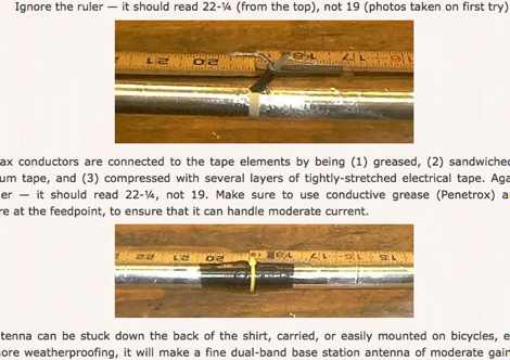 An off-center-fed sleeve dipole, made of CPVC and aluminum foil tape by KV5R
 -
 New Zealand Amateur Radio 70, 32 & 23 cm (UHF) Repeaters
 -
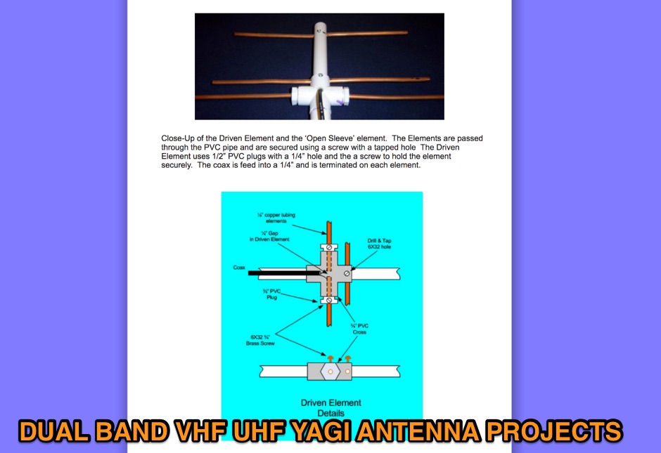 On this page are designs for Dual Band 2M / 70cm antennas. All antennas are 50 ohm designed driver. These Yagis have a unique element called a Open Sleeve. 4 Element 5 element and 9 element Dual Band - 2M / 70cm antenna projects
 -
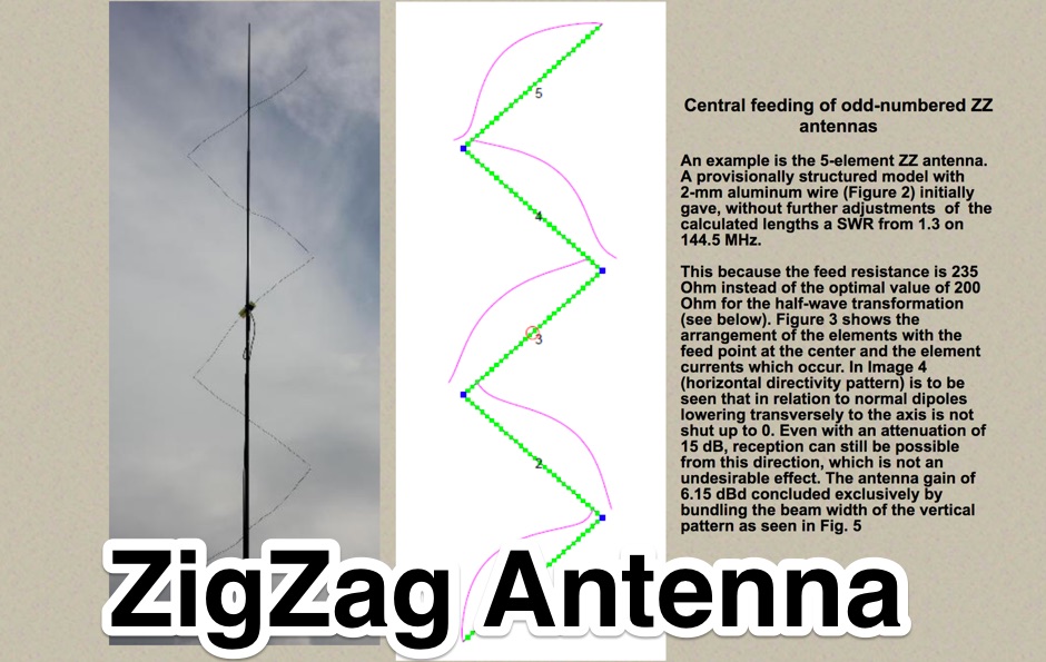 An unconventional antenna family, the VHF/UHF Zigzag Dipole Antennas. Design, theory and practical construction, transformation and balancing with a half wave balun.
 -
 K8GP web site, home of the Grid Pirates Contest Group.
 -
 AL-811 and AL-811H specifications and information about this 600-800 Watt ham radio ower amplifiers
 -
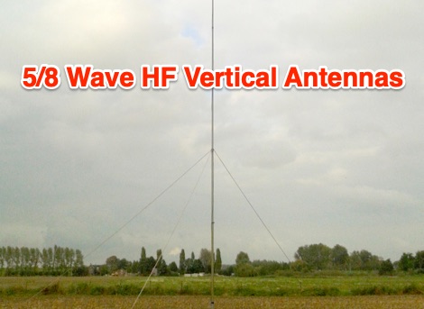 The advantage of 5/8 wave antenna is that it has the lowest angle of radiation and has about 1dB more gain when compared to 1/4 and 1/2 verticals. So the 5/8 should be the favourite choice for DX.
 -
 Layman level explanations of "seemingly" mysterious LF MF and HF propagation occurrences.
 -
 Discussion groups for Shortwave Listening, Propagation, Amateur Radio, and related topics.
 -
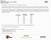 Sizes of wire as compared to their gauge American Wire Gauge by W8HDU
 -
 With spectrum analysis of beacon signals, it's possible to see features relating to various propagation phenomonen.
 -
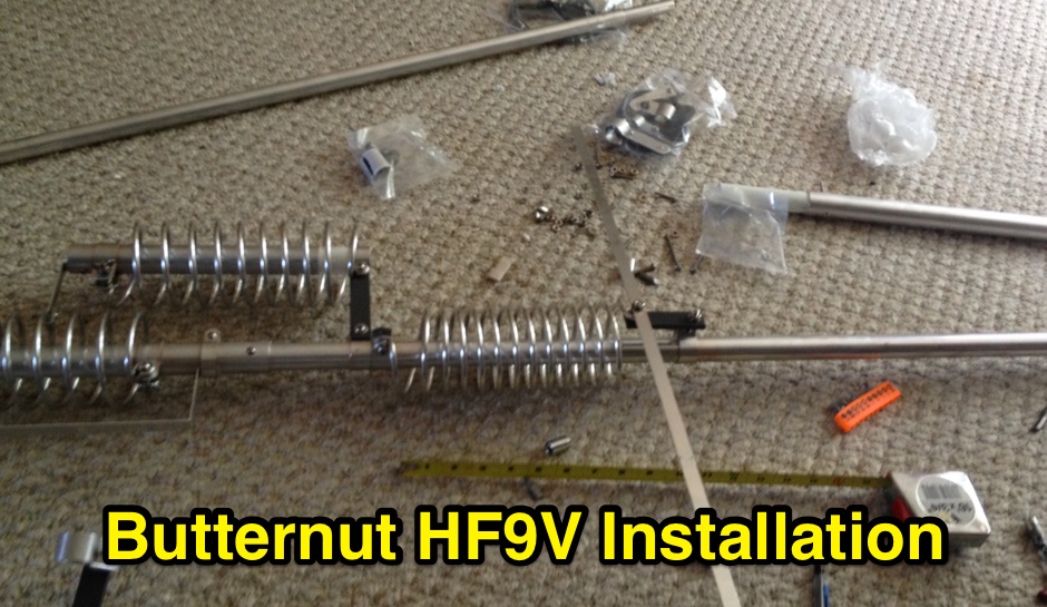 Assembling installing and tuning the Butternut HF9V multiband vertical antenna
 -
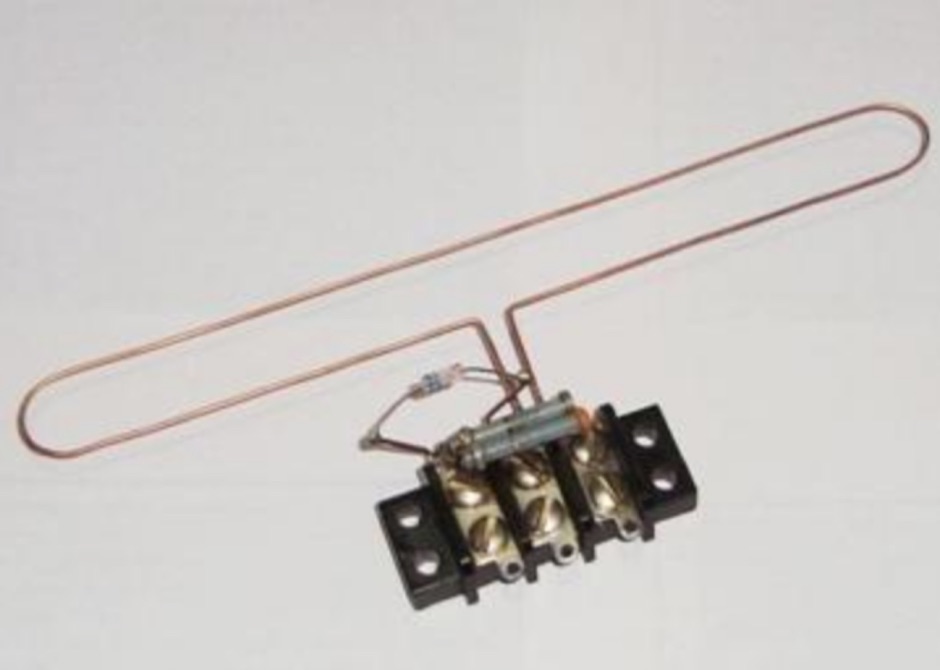 A simple UHF Crystal Radio wired up to check for reception of VHF/UHF signals in the vicinity of the shack.
 -
 A few thoughts on Multi Band VHF Aerials by Peter Ward VK3ZAV
 -
 Yaesu FT817 all band, all mode handheld transceiver article.
 -
 An economical dipole for simple QRP HF homebrew rigs
 -
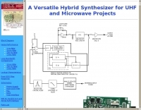 A versatile hybrid synthesizer for UHF and Microwave Projects
 -
 VHF channel usage, making a mayday call, and related informations
 -
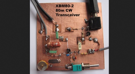 An 80m transceiver using just 14 parts plus crystal and earpiece
 -
 Mounting antenna close each other. Distance calculations and tips on setting up antennas by KB9VBR
 -
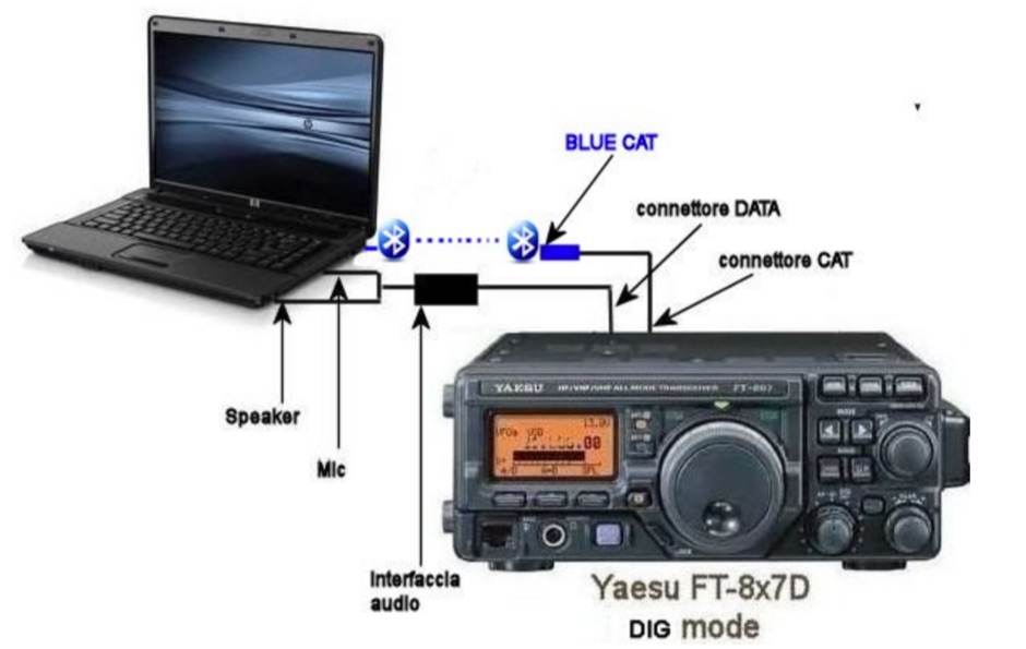 With the bluecat interface it is possibile to connect a Yaesu FT 817 857 897 to a computer or a android smartphone without any cable or interface, using a bluetooth wireless connection
 -
 This Magnetic Longwire Balun (MLB) makes it possible to efficiently use a coaxial lead-in cable with all forms of longwires, T-forms or other types of wire antennas, without the need for an antenna tuner.
 -
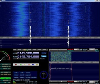 Article on RTL SDR dongles to receive UHF VHF ham radio bands
 -
 This method of construction can be used on most UHF through \"low\" microwave Yagis, and is especially useful for the 33, 23 and 13 cm bands