Search results
Query: HF operation
Links: 400 | Categories: 15
Categories
- Operating Modes > HF Operations
- Technical Reference > Amplifiers > VHF Amplifiers
- Radio Equipment > HF Amplifiers > Alpha 8410
- Radio Equipment > HF Transceivers > Elecraft KX2
- Radio Equipment > HF Transceivers > Icom IC-7851
- Radio Equipment > HF Transceivers > Kenwood TS-450S
- Antennas > Mobile
- Propagation > MUF Indicators
- Propagation > Propagation Forecast
- Radio Equipment > HF Transceivers > Ten-Tec Jupiter
- Antennas > W3EDP
- Operating Modes > WEFAX
- Radio Equipment > HF Transceivers > XIEGU G90
- Radio Equipment > HF Transceivers > Yaesu FT-2000
- Radio Equipment > HF Transceivers > Yaesu FT-847
-
 Details the construction of a portable _Moxon_ antenna optimized for the 2-meter band, utilizing readily available materials like 6.5 mm aluminum elements and a 15x15 mm TV boom. The design emphasizes ease of assembly and portability, making it suitable for field operations. Performance specifications derived from MMANA modeling indicate a forward gain of **6.3 dBi** and a front-to-back ratio of **15 dB**. Lateral attenuation is reported at 40 dB, with a minimum SWR of 1.1 at 144.300 MHz, confirming efficient operation within the target frequency segment. The antenna is lightweight at 500 grams, quickly assembled in approximately two hours, and disassembles into a compact 40x15x8 cm package. Direct feeding with RG-58 C/U or KX-15 coaxial cable via a BNC connector simplifies deployment.
 -
 The Elecraft K3, a popular HF transceiver, is often benchmarked against new market entrants. This article critically compares the Kenwood TS-590S to the K3, focusing on key technical specifications and operational aspects relevant to serious amateur radio operators. The author proposes three distinct evaluation methods: a circuit diagram comparison, an independent review analysis (referencing Peter Hart, G3SJX, in RadCom), and a real-world "ear test" by experienced contest operators on 40 and 80 meters. The analysis delves into specific receiver components, including the first mixer design, RF and IF amplifier performance, and the presence of an image noise filter. It highlights the K3's switched mixer and the potential for the TS-590S to utilize similar or improved designs, such as a classic filter with enhanced selectivity. The article also scrutinizes the second mixer stage, noting the K3's SA612 chip and its associated IP3 limitations, suggesting Kenwood might achieve benefits with a different mixer architecture. Further points of comparison include DSP capabilities, where the K3's high-performing DSP with KK7P's involvement is noted against the TS-590S's potential reliance on newer IC technology but possibly less refined software. The discussion extends to DDS and PLL implementations for phase noise and spurious emissions, and the utility of a second receiver for DX chasing and contesting, acknowledging its importance for some operators while being less critical for others. The article concludes by emphasizing personal preference in equipment selection.
 -
 Constructing an HF End-Fed Half-Wave (EFHW) vertical antenna, the resource details the winding of a monoband matching unit, inspired by _AA5TB_, designed to provide a 50 Ohm impedance match without a ground plane or antenna tuner. It specifies the use of a _T200-2_ ferrite core for the transformer, outlining the 13-turn secondary and 2-turn primary winding process with enamelled copper wire. The document also describes the integration of a coax capacitor, whose length is critical for tuning and varies by band, with specific starting lengths provided for 20m, 17m, 15m, 12m, and 10m operation. The practical application section guides the builder through tuning the antenna using an antenna analyzer, emphasizing the iterative process of spacing secondary windings and trimming the coax capacitor to achieve resonance at the desired band frequency. It highlights the antenna's low angle of radiation, beneficial for DX, and claims up to 2 S-points improvement over a _G5RV_ or similar doublet when used as an omnidirectional vertical. A comprehensive shopping list, including specific part numbers from _Rapid Electronics_, is provided, along with advice on selecting fiberglass fishing poles for support and suitable antenna wire.
 -
 Examines the operational principles of loading inductors within **mobile HF antennas**, clarifying their role in canceling capacitive reactance rather than physically replacing missing antenna length. It meticulously details how current distribution is influenced by stray capacitance and termination impedance, rather than the physical length of wire within the coil itself. The resource provides a deep dive into the behavior of inductors, emphasizing that a loading coil functions identically to any other inductor in an electronic circuit, with its characteristics determined by its design and surrounding impedances. This article specifically addresses common misconceptions, such as the idea that loading coil current is reduced by standing waves or that coils introduce a significant electrical-degree phase delay related to conductor length. It explains that magnetic flux coupling within the coil causes charges to move at light speed, resulting in minimal time delay across the inductor, especially in well-designed, compact units. The author, W8JI, presents both theoretical explanations and empirical measurements to support these points, including data from various antenna configurations. Furthermore, the content clarifies the distinction between voltage-current phase shift within an inductor and actual current time delay through it, using **SPICE models** and real-world observations. It highlights that large current taper in a loading coil often indicates poor antenna or tank circuit layout, rather than an inherent property of the inductor itself. The discussion also touches on the impact of stray capacitance on inductor Q and bandwidth, offering insights into optimal form factors for different applications.
 -
 Operating within the amateur radio HF spectrum requires adherence to established band plans and considerate practices. This guide from the ARRL outlines commonly accepted frequency ranges for specific modes and activities, spanning from 1.800 MHz to 29.680 MHz. It delineates segments for **CW**, **SSB**, RTTY/Data, SSTV, Digital Voice, and AM operations, including dedicated QRP calling frequencies and DX windows. The document emphasizes that these are not regulatory mandates but rather widely recognized conventions, acknowledging that high-activity periods like DXpeditions or contests may lead to temporary deviations. It explicitly references Section 97.101(b) of the FCC Rules, asserting that no station holds exclusive rights to any frequency. The guide also lists frequencies for IBP/NCDXF beacons and automatically controlled data stations. Practical advice is provided regarding frequency selection, stressing the importance of checking for existing use before transmitting. It also mentions ARRL band plans for frequencies above 28.300 MHz, directing operators to additional resources.
 -
 Catalogs over 9,300 radio transmissions heard within Finland, providing a detailed frequency database for Finnish radio enthusiasts. The resource lists frequencies for various services, including maritime VHF channel 16 at **156.800 MHz**, RHA68 channel 16 at 71.100 MHz, and _MIL AIR_ frequencies like 251.100 MHz. It also documents air traffic control frequencies, such as 123.775 MHz for Area Control and 127.000 MHz for Approach Control, alongside frequencies for Finnish Air Force operations at 140.550 MHz. The database includes entries for commercial shared channels at 170.450 MHz and 458.250 MHz, as well as specific local business frequencies like 443.125 MHz for Sale Merimasku. Shortwave broadcast entries are also present, noting stations like BBC at 6.035 MHz from Tashkent and AIR Akashvani Ext.Sce at 11.900 MHz from Bangalore. The site organizes its extensive listings by categories such as "Liikenne" (Traffic) with 2397 entries, "Radioamatoori" (Amateur Radio) with 781 entries, and "Yle" (General) with 2305 entries. The database was last updated on 26.2.2024, reflecting ongoing maintenance and additions to its comprehensive collection of Finnish radio spectrum data.
 -
 A 3.42-meter (11-foot 2-inch) extended-length mobile antenna project is presented, detailing its evolution from an initial 1.65-meter design. W5JGV shares his journey in optimizing mobile HF performance, noting that increasing the top whip length significantly improved radiation efficiency by reducing coil losses and allowing for larger wire gauges. The article includes a comparative table illustrating substantial gain increases, with the 3.42-meter version showing up to 40.6% efficiency on 21.2 MHz compared to a half-wave dipole. Construction details are thoroughly documented, from the use of hard-wall copper pipe for mast sections to the fabrication of custom loading coils. The author explains the necessity of an insulating brace for self-supporting coils and details a unique rotational alignment mechanism for off-center mounted coils to prevent snagging on overhead obstructions. He also describes a "Z" winding technique for 75-meter and 160-meter coils, which minimizes copper losses and manages dielectric losses. The resource provides specific loading coil data, including wire gauge, number of turns, coil length, and inductance values for bands from 18 MHz down to 2 MHz. It emphasizes that these coils may require fine-tuning based on individual vehicle and whip configurations, suggesting an antenna tuner for optimal mobile station operation across multiple HF bands.
 -
 Over 75 years of engineering expertise underpins Bird Electronic's offerings in RF power measurement, critical for maintaining peak performance in amateur radio stations and professional communication systems. The company specializes in a range of test equipment, including wattmeters, SWR meters, and antenna analyzers, essential for optimizing antenna systems and ensuring efficient power transfer. Their product line extends to various RF components such as filters, cables, and connectors, all designed to meet stringent technical specifications for reliability and accuracy across diverse frequency bands. Bird Electronic's instruments, like the _Bird 43_ Thruline Wattmeter, are widely recognized for their robust construction and precise measurement capabilities, providing hams with confidence in their station's operational parameters. These tools enable accurate assessment of forward and reflected power, SWR, and modulation characteristics, which are vital for troubleshooting and maximizing radiated power. The company's commitment to innovation ensures that its products remain relevant for modern RF challenges, from HF through microwave applications, supporting both traditional analog and advanced digital modes.
 -
 Designing a compact directional antenna for the 70cm band involves balancing gain, front-to-back ratio, and physical size. This resource details the construction of a 2-element Moxon rectangle antenna for 432 MHz, outlining the specific dimensions for the driven element and reflector, and discussing the advantages of its folded dipole configuration. The article provides insights into the historical context of 70cm operations and the author's personal experiences with early 432 MHz transceivers and antenna setups, such as a Jaybeam 48-element TV antenna. It also touches upon the practical aspects of building and deploying such an antenna for local and weak-signal work. The Moxon antenna design is compared to a 3-element Yagi, noting its superior front-to-back ratio and broader bandwidth for a given boom length, making it suitable for portable operations or restricted spaces. The construction uses readily available materials like copper wire and PVC tubing, emphasizing simplicity and ease of replication. Performance characteristics, including a reported gain of approximately 5.5 dBi and a front-to-back ratio of 20 dB, are discussed in the context of its compact footprint. The resource includes a visual representation of the antenna's dimensions and construction, aiding in practical implementation.
 -
 Reccomendations and tips for VHF-UHF operation
 -
 If you can't get on the air from home, the Internet may provide the answer. By Brad Wyatt, K6WR. Pdf File.
 -
 Calculates precise dimensions for **Moxon rectangle** HF antennas, enabling hams to design antennas by inputting desired resonant frequency and wire diameter. This web-based tool, version 0.5, is a PHP front-end developed by W4/VP9KF, based on a public domain BASIC program originally authored by L. B. Cebik, W4RNL. It generates critical measurements for the driven element and reflector, ensuring proper spacing and element lengths for optimal performance. User feedback confirms the calculator's accuracy, with one user reporting resonance within 50 Hz of the design frequency for an 18 MHz antenna, eliminating the need for SWR adjustments. This contrasts with other online tools that resulted in significant frequency discrepancies. The tool's precision facilitates building **directional antennas** for specific bands, contributing to effective DXing and contesting operations.
 -
 In 1999, W5GVE presented a detailed construction article for a 2-meter _DDRR_ antenna, specifically designed for mobile operation. This unique antenna, a Directional Discontinuity Ring Radiator, offers a compact footprint, making it suitable for vehicular mounting where traditional quarter-wave verticals might be impractical. The design emphasizes ease of homebrewing, utilizing readily available materials and basic workshop tools, allowing radio amateurs to build an effective mobile antenna for the 144 MHz band. The article provides insights into the antenna's performance characteristics, noting its low profile and potential for reduced wind loading compared to taller mobile whips. W5GVE's experience with the DDRR design suggests it can provide reliable communications on the 2-meter band, even in challenging mobile environments. The construction details include specific dimensions and assembly steps, guiding the builder through the process of creating a functional antenna. This project offers a practical alternative for hams seeking a discreet yet effective 2-meter mobile antenna, potentially achieving **3 dB** gain over a standard mobile whip.
 -
 The 6 Band Inverted L Antenna MK3 is a versatile multiband antenna designed for amateur radio operators. This antenna covers 160m, 80m, 40m, 20m, 15m, and 10m bands, making it suitable for a wide range of HF communications. The design is based on a W3DZZ configuration, incorporating traps for optimal performance. The MK3 version features a sturdy 5/8th CB mast, replacing the original timber mast, which enhances durability against harsh weather conditions. The antenna's construction allows for effective operation, particularly on the 40m band, where it has been successfully used to contact distant locations including ZL, VK, and Antarctica. Constructing this antenna requires careful attention to detail, especially regarding the radials and grounding. The traps resonate at specific frequencies, and additional resources are available for building coaxial traps. The antenna is designed to work efficiently without an ATU on the lower bands, while higher bands may require tuning. This project is ideal for both beginner and intermediate operators looking to enhance their station with a reliable multiband antenna.
 -
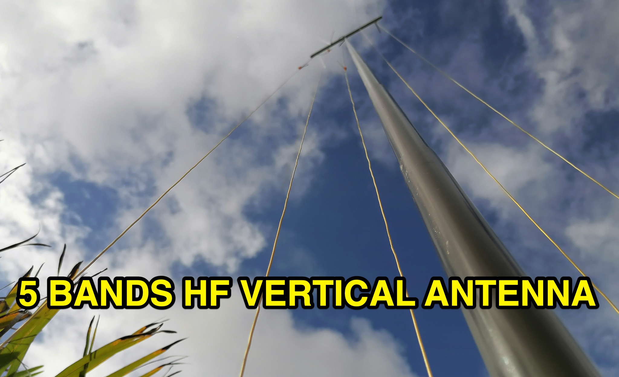 A quarter-wave vertical antenna design for HF operation offers a practical solution for radio amateurs seeking a compact and efficient multi-band radiator. This project details the construction of a 5-band HF vertical, drawing inspiration from established commercial products such as the _DX COMMANDER_ and the MV6. The design emphasizes ease of assembly and disassembly, making it suitable for portable operations or installations with limited space. The article provides insights into various construction methods and offers practical tips for building a robust yet lightweight antenna. It highlights the benefits of a vertical configuration for DX contacts, particularly on the lower HF bands, and discusses real-world performance observations. The antenna is designed to cover multiple HF bands, providing versatility for various operating scenarios. Operators can achieve significant DX results with this type of antenna, often comparable to more complex arrays, especially when deployed with an effective ground system. The project aims to empower hams to build a capable antenna without significant financial outlay.
 -
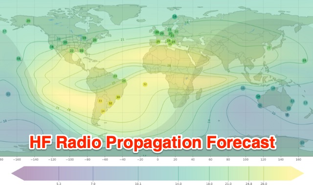 Understanding high-frequency (HF) skywave propagation is crucial for amateur radio operators seeking to optimize long-distance communications. This resource details the fundamental principles of HF radio propagation, including the properties of electromagnetic waves, the characteristics of various HF bands, and distinct propagation modes such as skywave, ground wave, and line-of-sight. It places significant emphasis on the ionosphere's pivotal role in refracting HF waves, explaining how solar activity directly influences ionospheric conditions and, consequently, propagation paths. The resource integrates real-time monitoring capabilities, featuring dynamic charts and data from DX clusters, WSPRnet, and the Reverse Beacon Network, which allow users to track current band activity and propagation conditions globally. It also delves into advanced topics like Near Vertical Incidence Skywave (NVIS) and gray line propagation, providing insights into ionosonde data and various propagation prediction models. The site presents a detailed analysis of solar-terrestrial interactions, geomagnetic indices, and space weather phenomena, illustrating their direct impact on HF communication reliability. Practical tools and applications are highlighted, including real-time QSO planners, online Maximum Usable Frequency (MUF) maps, and alerts for solar flares or geomagnetic storms. The guide systematically breaks down complex concepts into accessible chapters, offering a structured approach to learning about ionospheric regions, diurnal and seasonal effects, and the interpretation of propagation indicators like foF2, MUF, and Lowest Usable Frequency (LUF). This makes it a robust reference for hams aiming to deepen their technical understanding and improve operational effectiveness.
 -
 Constructing a compact, two-band magnetic loop antenna for HF operation, especially from constrained locations like a balcony, presents unique challenges. OK1FOU's design, inspired by DJ3RW's 50 MHz loop, addresses these by employing an unusual side-fed configuration and placing the symmetric, two-section variable tuning capacitor at the bottom of the loop, directly connected to the coax shield. The article provides specific material recommendations, including two 1-meter wooden pales and about 3 meters of thick loudspeaker cable, noting the high current (60A at 100W) in the loop. Construction steps detail forming two turns with a 5 cm gap, using a GDO to pre-tune the open loop to a frequency slightly above the desired highest band, and then integrating the tuning and coupling capacitors. For 10/14 MHz, an open loop resonance of 16-17 MHz is suggested. Practical experience with the 10 MHz band from a third-floor balcony in Prague (JO70GC) shows a 1:1 SWR across most of the band without an external ATU. While DX traffic was modest due to the urban environment, QSO examples with RA6WF, LA6GIA, G0NXA, and LZ1QK on 10 MHz are provided, demonstrating its operational capability.
 -
 The RigPix database entry provides a comprehensive technical overview of the Icom IC-746 amateur HF/VHF transceiver, detailing its operational parameters and physical characteristics. It specifies the transmit frequency ranges across 10-160 meters plus WARC bands, 50-54 MHz, and 144-146/148 MHz, alongside receive coverage from 0.03-60 MHz and 108-174 MHz. The resource outlines supported modes including AM, FM, SSB, CW, and RTTY, noting a tuning step resolution down to 1 Hz and a frequency stability of ±5 ppm. Key electrical specifications are presented, such as a 13.8 VDC power supply requirement, current drain figures for RX (1.8-2 A) and TX (Max 20 A), and RF output power ranging from 5-40 W for AM and 5-100 W for FM, SSB (PEP), and CW. The entry details the triple conversion superheterodyne receiver system, listing IF frequencies at 69.01 MHz, 9.01 MHz, and 455 KHz, along with sensitivity ratings for various modes and bands. Transmitter section specifics include modulation systems and spurious emission levels. Additional features like a built-in auto ATU, electronic keyer, simple spectrum scope, DSP, and CI-V computer control are noted. The page also lists related documents, modifications, and an extensive array of optional accessories, including various filters, microphones, and external tuners, providing a complete profile of the IC-746.
 -
 The idea of using a low mount dipole, enhanced with reflector wires directly beneath the dipole, on the ground, appears to be a very good approach to creating an NVI specific antenna for local HF operation.
 -
 JJ0DRC's HF multi-band delta loop antenna project, initially conceived during the waning peak of Cycle 23, addresses the common challenge of achieving effective DX operation from a small residential lot in Japan. Dissatisfied with a ground plane antenna's performance in SSB pile-ups, the author sought a beam-like solution without a tower, drawing inspiration from a JJ1VKL article in CQ Ham Radio Sep. 2000. The antenna, constructed in October 2000, employs two 7.2-meter fishing rods (37% carbon fiber, reinforced with cyano-acrylate glue and aluminum tape) and 1mm enameled wire, fed by an Icom AH-4 external antenna tuner. While the exact beam pattern remains unmeasured, JJ0DRC observed a significantly higher callback rate compared to dipole antennas, particularly on higher bands. The system's circumference length of 15-20m is crucial for maintaining a good beam pattern across HF bands, though performance on lower bands like 80m, 40m, and 30m becomes less directional as the length deviates from a full wavelength. Ongoing maintenance addressed degradation issues, including aluminum tape cracking and wire breakage at connection points due to strong winds (often exceeding 10-15m/s in winter). The author reinforced rod connections with IRECTOR PIPE SYSTEM components and INSU-ROCK ties, and improved wire attachment methods using Cremona rope and epoxy bond to enhance durability.
 -
 This resource details the computer-optimized design of the _ZS6BKW_ multiband dipole, an evolution of the classic _G5RV_ antenna. It begins by referencing the original 1958 RSGB Bulletin article by Louis Varney G5RV, explaining the operational principles of the G5RV's flat-top and open-wire feedline on 20m and 40m, noting its impedance transformation characteristics for valve amplifiers of that era. The article then transitions to the rationale for optimizing the design for contemporary solid-state transceivers requiring a 50 Ohm match. The core of the project involves using computer modeling to determine optimal lengths for the flat-top and matching section, aiming for a VSWR of less than 2:1 on multiple HF bands. It discusses the process of calculating feedpoint impedance based on antenna length and frequency, referencing professional literature from Professor R.W.P. King at Harvard University. The analysis also considers the characteristic impedance (Z(O)) of the open-wire line, identifying a broad peak of adequate values between 275 and 400 Ohms. Specific design parameters for the improved ZS6BKW are presented, including a shorter flat-top and a longer matching section compared to the original G5RV, with a velocity factor of 0.85 for the 300 Ohm tape. The article confirms acceptable matches on 7, 14, 18, 24, and 28 MHz bands when erected horizontally at 13m, and also discusses performance in an inverted-V configuration, noting frequency shifts. The author, Brian Austin ZS6BKW, emphasizes the antenna's suitability for modern 50 Ohm coaxial cable without a balun.
 -
 Presents the design and construction of the OK2FJ Bigatas, a portable, automatically tuned vertical antenna covering 80 through 10 meters. It details two distinct control systems: one utilizing BCD band data from Yaesu FT-857/897 transceivers, and another employing voltage level sensing for the Yaesu FT-817. The resource provides specific instructions for building the antenna's radiating element, loading coil with switchable taps, and the control circuitry, emphasizing the use of readily available components. The article outlines the physical construction of the antenna, including the use of duralumin tubes for the radiator and a PVC tube for the coil form. It specifies coil winding details, tap points, and the integration of radial wires for ground plane operation. The control electronics section provides schematics and component lists for both the BCD decoder (using a 74LS42 IC) and the voltage comparator (using an _LM3914_ bargraph driver), enabling rapid, automatic band switching without the minute-long tuning delays common in other systems. Crucially, the antenna achieves rapid band changes, with typical SWR values centered on common operating segments, such as **3.7 MHz** for 80m SSB. It also discusses modifications for CW operation on 80m and the trade-offs between antenna efficiency and full-range automatic tuning on higher HF bands, where manual adjustment of radiator length is suggested for optimal performance on 15m, 12m, and 10m. The resource includes construction photos and a discussion of cable requirements for reliable operation.
 -
 Demonstrates the construction of a base-loaded quarter-wave vertical whip antenna, suitable for both mobile and portable HF operations. This design utilizes a vehicle body as a ground plane for mobile use or a counterpoise for field deployment. The article details the selection of materials, such as a _glass fibre tubing_ former and 24 s.w.g enamelled copper wire for the loading coil, with specific turn counts suggested for 20m (around **30 turns**) and 40m (around **50-60 turns**). It outlines a practical tuning method using an SWR bridge and even an audible signal approach, emphasizing careful adjustment of coil turn spacing or whip length to achieve optimal SWR. The resource also mentions the use of an antenna analyzer for more precise tuning, contrasting it with the SWR method.
 -
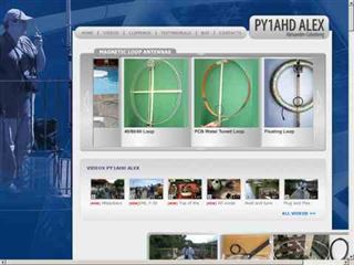 HF pedestrian operation using loop antennas by PY1AHD
 -
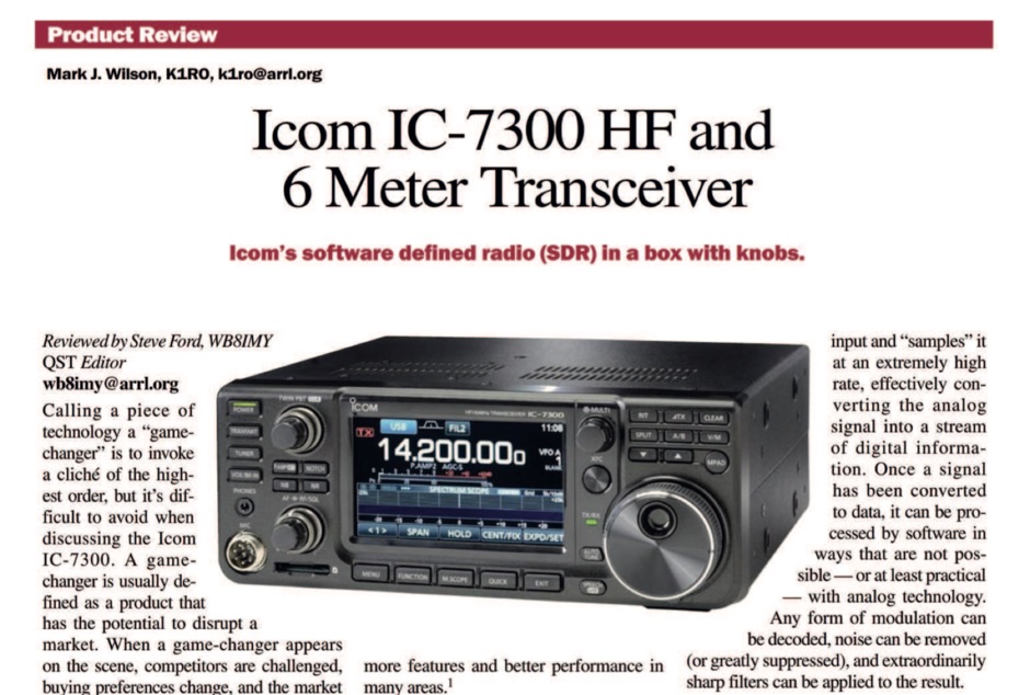 The ICOM IC-7300 is a cutting-edge HF transceiver that has garnered significant attention since its release. This review, published by ARRL in QST, provides an in-depth analysis of its features, performance, and usability. The IC-7300 is known for its direct sampling technology, which enhances its sensitivity and selectivity, making it a favorite among amateur radio operators. The review covers various aspects, including the user interface, audio quality, and overall operational capabilities, providing valuable insights for both new and experienced hams. In addition to its technical specifications, the review discusses the IC-7300's performance in real-world scenarios, such as DXing and contesting. It highlights the transceiver's ability to handle weak signals and its versatility across different modes. The review serves as a helpful guide for those considering the IC-7300 for their station, offering a balanced perspective on its strengths and potential drawbacks. Overall, this review is an essential resource for anyone interested in the ICOM IC-7300 and its place in the amateur radio landscape.
 -
 The DXrobot, operational since 1999, offers a free, non-commercial service primarily for the VHF ham radio community. It specializes in automatic real-time E-skip warnings for **144 MHz** in both Europe and North America, delivered via email or SMS. Additionally, the system provides automatic aurora alerts for _50, 70, and 144 MHz_ openings through the same notification methods. Beyond real-time alerts, the DXrobot facilitates the reception of the latest DX-cluster spots via email, a feature useful for operators without immediate WWW or cluster access. The service also displays recent E-skip and aurora spots detected by the DXrobot on 50, 70, and 144 MHz, with updates every five minutes. Historical data includes lists of all DX spots from the previous day on 50, 70, and 144 MHz, updated daily. Key propagation data, such as MUF timeline, Solar X-rays, Geomagnetic Field, and Estimated Kp index, are also presented.
 -
 The FTBVR5K software facilitates comprehensive memory management for the Yaesu VR-5000 scanning receiver, supporting operations such as modifying, moving, adding, deleting, masking, and unmasking individual memories. It allows for importing and exporting memory definitions via CSV files, sorting memories by frequency or name, and identifying duplicate frequencies within the receiver's configuration. The program also supports the creation and modification of bank definitions, management of PMS (Programmable Memory Scan) definitions, and adjustment of PMS scanning ranges. Additionally, users can print detailed reports of memories, banks, PMS definitions, rig settings, and S.CALL details, with visual cues like red highlighting for masked memories and yellow for the priority channel. FTBVR5K provides functionality to alter values within the VR-5000's Set and Config menus, and to change S.CALL station names and frequencies. The application operates on standard Windows PCs, including Windows XP, Vista, 7, 8, and 10, requiring an available COM port for transceiver connection, which can be a conventional serial port or a USB adapter. A minimum screen resolution of 800 x 600 is supported, with 1024 x 768 recommended for optimal usability.
 -
 Antenna was designed for SO-50 satellite operation but can be used for any VHF/UHF activity. It's a mix of a Moxon Antenna and a Yagi antenna. It has gains 4 dBd on 2m and 6.5 dBd on 70cm bands and it is fed via single 50 Ohm cable.
 -
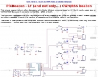 This resource details the construction of a versatile CW/QRSS beacon, designed around a Microchip _PIC16F84_ microcontroller. The project provides a flexible platform for transmitting either standard CW or very slow QRSS signals, making it suitable for LF, VHF, UHF, and SHF applications. It supports two distinct messages, each configurable for speed (from 0 to **127** WPM for CW, or up to **127** seconds per dot for QRSS) and repetition within a six-phase sequence. The core functionality relies on the PIC's EEPROM, which stores all operational parameters, including message content, transmission speeds, phase configurations, and relay control settings. This design allows for parameter modification directly via programming software like _ICProg_ without altering the main program code. The project includes a detailed schematic, a component list, and an explanation of the EEPROM memory mapping for messages, speeds, phase settings, and inter-phase delays. General-purpose outputs (OUT1, OUT2, OUT3) provide dry relay contacts for external control, enabling functions such as power switching, antenna selection, or frequency changes. A 'TRIGGER' input facilitates controlled starts or continuous free-run operation. Sample EEPROM configurations illustrate how to program specific beacon sequences, including message content and relay states.
 -
 Illustrates the specific wiring and configuration steps required to interface an SGC-230 Smartuner with an Icom IC-706 HF/VHF/UHF transceiver. The document details the necessary connections for power, control, and RF signal paths between the two devices, ensuring proper impedance matching and automatic antenna tuning functionality. It specifies the pin assignments for the IC-706's ACC socket and the SGC-230's control port, crucial for successful integration. Outlines the operational considerations for the combined system, including initial setup procedures and potential troubleshooting tips for common connectivity issues. The resource presents a clear, diagrammatic representation of the interconnections, which aids in visual comprehension of the required cable fabrication or modification. Covers the specific settings within the IC-706 menu that need adjustment to enable external tuner control, such as the 'TUNER' function and other relevant parameters. This ensures the transceiver correctly communicates with the SGC-230 for efficient antenna tuning across various amateur bands.
 -
 The Q-signal **QRP** signifies a request to reduce power, and in amateur radio, it defines operating with 5 watts or less for CW and 10 watts or less for SSB. This article addresses common inquiries from new hams regarding the practice, its benefits, and implementation methods. It explains how a 5-watt QRP signal, compared to a 100-watt signal, typically results in only a 13dB drop in signal strength, equating to about two S-units, still providing solid copy under most conditions. Hams choose QRP for various reasons, including seeking a greater challenge in DXing or contesting, reducing band interference, or enabling portable field operations with lightweight, battery-efficient equipment. A modern single-band CW transceiver, key, and antenna can fit into a pocket, offering receiver performance comparable to commercial rigs and extended operation on a small battery. This portability facilitates operations in remote locations where higher-power setups are impractical. Operating QRP can involve simply reducing power on an existing commercial HF rig or building a dedicated QRP transceiver from a kit, such as the **Wilderness Radio SST** with its 2-watt output and 15mA receive current draw. While SSB is viable, CW remains the most popular and efficient mode for QRP due to its superior signal-to-noise ratio. The article lists common QRP calling frequencies across 160m through 10m bands for both CW and SSB, and highlights organizations like QRP ARCI and NorCal that support the QRP community.
 -
 The ZS6BKW wire antenna, a variant of the G5RV, utilizes a specific 13m (42.6 ft) length of 450-ohm window line as its matching section, feeding a 28.5m (93.5 ft) flat-top element. This design aims for lower SWR on 40m, 20m, 17m, 12m, and 10m compared to a standard G5RV, often achieving SWR values below 1.5:1 on these bands without an antenna tuner. The feedpoint impedance transformation provided by the window line allows for direct connection to 50-ohm coax on multiple bands. F4FHH's experience involved constructing the ZS6BKW and evaluating its performance against an _OCF dipole_ (Off-Center Fed) on various HF frequencies. The article includes observations on SWR readings and operational effectiveness, highlighting the ZS6BKW's suitability for multi-band operation. The antenna's overall length, including the flat-top and window line, is approximately **41.5 meters** (136 feet), making it a significant wire antenna for fixed station use. Comparative analysis with the OCF dipole provided practical insights into the ZS6BKW's advantages and limitations, particularly concerning bandwidth and tuner requirements.
 -
 New User Tips for VHF-UHF Operation by Dave Schultheis WB6KHP
 -
 Presents the Light Loop, a small magnetic loop antenna optimized for 40m through 10m operation, demonstrating its construction for portable QRP use. The design emphasizes lightweight materials and a compact form factor, making it suitable for handheld or backpack deployment during field activities. It details the primary radiating element, the coupling loop, and the variable capacitor required for resonance across the specified HF bands. The article provides specific component choices, such as the 1.5-inch diameter aluminum tubing for the main loop and the 10-365 pF variable capacitor for tuning. It discusses the importance of precise loop circumference and spacing for efficient impedance matching and bandwidth characteristics. The resource includes practical advice on achieving resonance and optimizing performance for low-power transceivers. Construction notes cover the mechanical assembly, including mounting the capacitor and feedpoint connections. It highlights the antenna's suitability for pedestrian mobile operations, offering a practical solution for HF communication without extensive setup. The design aims for a balance between portability and effective radiation on the lower HF bands.
 -
 Compiling an extensive collection of technical information, the Repeater Builder's website serves as a critical resource for those involved in amateur and commercial repeater systems. It covers a broad spectrum of topics essential for the design, construction, and ongoing maintenance of these vital communication hubs, drawing from years of practical experience in the field. The site provides detailed insights into various aspects of repeater technology, including specific information on VHF and UHF bands, such as 2-meter systems. Users can find data related to repeater logic, control systems, and interfacing with other radio infrastructure, all presented with a focus on practical application. Authored by Kevin Custer, W3KKC, the content reflects a deep understanding of repeater operations and engineering, offering guidance that extends beyond basic setup to advanced troubleshooting and optimization.
 -
 Demonstrates the iterative design and construction of a **tapped HF/VHF mobile vertical antenna** by K0EMT, detailing four generations of development. The antenna supports operation on 80m, 40m, 30m, 20m, 17m, 15m, 12m, 10m, 6m, and 2m bands. Initial designs, like Generation 1, featured a 3/8" x 24TPI bolt in a PVC end cap with a 1" aluminum tubing mast, resulting in a 9'9" overall length and resonance around 6.9 MHz with the full coil. Subsequent generations refined the mast and coil forms, transitioning from aluminum to copper tubing (Generation 3, found too weak) and eventually fiberglass for the coil form (Generation 4, in progress). Coil tapping points were adjusted to achieve resonance without an external tuner in Generation 2. The project outlines material costs, totaling approximately $25, and mentions a successful 28 MHz QSO with EA3XA using an ICOM IC-706 mk II at 100 Watts. For 80m operation, an external wire with the maximum coil setting is used, or a 56" extender below the coil for stationary use.
 -
 A must read guide for all new and old operators. This document was originally written with the prime focus on DXing and pileup behavior. Suggestions by proofreaders have been implemented; the document is not as narrowly focused anymore as originally intended. It contains hints, tips and tricks for newcomers as well as old-timers. Additionally there are VHF/UHF operational matters, DX Cluster ethics, COPS, Conflict Situations and more.
 -
 Presents the detailed construction of the _FLA25HV_ antenna, a specialized array optimized for Earth-Moon-Earth (EME) communications on the 2-meter band. This resource provides schematics and practical insights into building a high-gain antenna system capable of reflecting signals off the lunar surface, a challenging but rewarding aspect of amateur radio. It covers the mechanical and electrical considerations essential for achieving the precise pointing and signal strength required for successful moonbounce contacts, often yielding **20 dB** or more gain. Amateur radio operators pursuing EME operations require robust antenna systems and precise tracking capabilities. The FLA25HV design addresses these needs by focusing on element spacing, impedance matching, and structural integrity to withstand environmental factors while maintaining critical alignment for lunar reflections. Such systems are crucial for making contacts over distances exceeding **768,000 km**. This personal page serves as a practical guide for hams interested in constructing their own EME arrays, offering a glimpse into the technical dedication involved in pushing the boundaries of VHF/UHF propagation.
 -
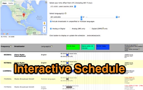 HFCC manages and co-ordinates global databases of international shortwave broadcasting in keeping with International Radio Regulations of the ITU. Operational Schedule, available for free download and iteractive schedule
 -
 This resource details the construction of a mobile screwdriver antenna, patterned after the original W6AAQ DK3 design from 1991. It covers the mechanical and electrical aspects of building a robust, multiband HF antenna for vehicular operation. Specific components discussed include the lower mast section, the coil wound on Schedule 40 PVC pipe, beryllium copper contact fingers, the motor drive assembly utilizing a Black & Decker screwdriver, and the capacity hat design with a brass hub and steel wires. The article provides insights into material selection, such as heavy copper tubing and silicone grease for assembly, and addresses practical considerations like coil length limitations for 80m operation due to lathe size. The construction results in an antenna capable of tuning from 6.5 MHz (40m) up to 6m, with slightly reduced range when the capacity hat is installed. The author describes the mounting base with soldered brass nuts for secure attachment and a U-channel bracket for vehicle mounting on a Dodge Ram 1500. The article includes close-up photographs illustrating the coil, contact fingers, drive mechanism with rubber tubing clutches, and the capacity hat assembly. It also mentions the use of Rustoleum hammer finish enamel for painting the copper pipe, indicating attention to durability and aesthetics.
 -
 A new SDR-receiver from the italian SDR developers community. Low-cost, DDS-less Software Defined Radio full coverage receiver for all HF bands, used with powerful software on the PC for multi-mode operation
 -
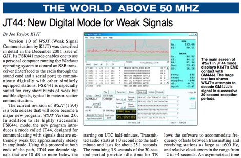 Moon bounce EME, meteor scatter and weak signal operations, introduction by ARRL.
 -
 A _Topfkreis_ antenna, also known as a "bicycle pump" antenna, is presented as a simple vertical design for the 70 cm band. This variant of the J-pole antenna is notable for not requiring a ground plane, simplifying deployment. The construction details specify using aluminum tubing for the radiating element, with precise measurements for the quarter-wavelength outer tube (32 mm diameter) and the three-quarter wavelength inner sliding tubes (10 mm and 8 mm). Feeding is via a 50-ohm coaxial cable connected 90 mm from the base of the central tube. This design can achieve a gain of **4 to 6 dB** when properly tuned using the adjustable radiating element. The article details the fabrication of a critical aluminum washer, suggesting a method using a hole saw and a drill press as a lathe for precise adjustment. The illustrated example is specifically for the 70-centimeter band, and the author, Pop, clarifies construction points in the comments, including material choices and assembly techniques, ensuring a robust build for VHF/UHF operation.
 -
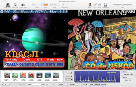 Operating Slow Scan Television (SSTV) on Apple macOS systems requires specialized software to encode and decode images for transmission over amateur radio frequencies. MultiScan 3B was an application designed for this purpose, enabling Mac users to engage in SSTV communications. It supported various popular SSTV modes, including Robot Black & Color, Scottie, Martin, PD modes (P3, P5, P7), and AVT, catering to a wide range of operational preferences and compatibility requirements within the SSTV community. The software's capabilities extended to both transmitting and receiving pictures, offering flexibility in how images were processed. Users could select regular, narrow, QRM, and narrow+QRM modes, allowing for adaptation to different band conditions and signal environments. This feature was particularly useful for mitigating interference and optimizing image quality during transmissions on HF bands. MultiScan 3B was built to run on Mac OS X 10.6 and later versions, providing a dedicated solution for Mac users interested in this classic digital mode. Its support for multiple modes and operational settings made it a versatile tool for SSTV enthusiasts.
 -
 The document details the construction of a compact, two-element Quad antenna specifically designed for the 10, 12, and 15-meter HF bands, featuring a single feedline for all three bands. It provides specific dimensions for the driven element and reflector loops, along with boom length and spacing, emphasizing a **0.12 wavelength** spacing between elements. The design incorporates a gamma match for impedance transformation and uses PVC tubing for spreaders, aiming for a lightweight yet robust structure suitable for portable or restricted-space operations. Performance measurements indicate a forward gain of approximately **6 dBd** on 10 meters and a front-to-back ratio of _20 dB_ on 15 meters, demonstrating effective directivity and signal rejection. The antenna exhibits a VSWR below 1.5:1 across the target bands, achieved through careful tuning of the gamma match. This compact Quad offers a viable directional solution for HF DXing and contesting, particularly where full-size Yagis are impractical.
 -
 Operational testing of a 10.07-meter portable HF vertical antenna, constructed from telescoping aluminum tubing (36, 32, 22, 17 mm diameters), yielded SWR measurements below 1.5 across multiple bands. Initial trials on 14.150 MHz showed an SWR of 1.6, while 7.075 MHz was problematic. Subsequent adjustments, including a 13 cm extension to the radiating element, improved performance, enabling operation on 6, 15, and 40 meters without a balun, and adding 12 meters with a balun. The design prioritizes portability, allowing transport in a standard vehicle and single-person deployment. Four 10.07-meter radials are connected at the base to enhance ground plane effectiveness. The article details the mechanical assembly, including custom adapters for tube transitions and a PVC sanitary tube sleeve for base insulation, ensuring robust field deployment. Final SWR measurements, documented with an _MFJ-259_ antenna analyzer, confirm operational ranges: 6.800-7.500 MHz (SWR < 1.5), 20.800-22.500 MHz (SWR < 1.5), and 48.800-51.500 MHz (SWR < 1.5) without a balun. With a balun, the antenna achieved SWR < 1.5 on 13.750-15.000 MHz and 24.890-28.350 MHz, demonstrating its versatility for portable _DXpeditions_.
 -
 Constructing an effective mobile antenna system for HF bands often presents challenges in achieving multi-band operation with a compact footprint. This project details the assembly of a versatile mobile antenna utilizing a standard _Hamstick_ base, enabling operation across 40, 20, 15, and 10 meters. The design incorporates a 102-inch whip and a custom-fabricated coil, allowing for quick band changes by adjusting the coil tap point. The document provides a parts list, step-by-step assembly instructions, and tuning considerations for optimizing SWR on each band. It emphasizes practical construction techniques for the coil and mounting hardware, ensuring mechanical integrity for mobile use. The antenna's performance is discussed in the context of typical mobile operating environments, highlighting its adaptability for various HF frequencies. Final adjustments involve precise trimming of the whip and coil taps to achieve resonance, with a focus on minimizing losses and maximizing radiation efficiency.
 -
 All Band HF Doublet for operation over all HF bands including 160m.
 -
 The PDF document, titled "J-Poles," presents various J-pole antenna designs covering the 50 MHz to 450 MHz frequency range. It includes construction details for several specific bands, such as a 6-meter J-pole, a 2-meter J-pole, and a 70-centimeter J-pole. The content outlines the fundamental principles of J-pole operation, including the quarter-wave radiator and half-wave matching stub. Each design features specific dimensions for elements like the radiator length, stub length, and spacing, often expressed in inches. The document also discusses feeding arrangements and impedance matching considerations inherent to J-pole antennas. It provides practical guidance for homebrewing these antennas using common materials like copper pipe or wire elements. The resource offers insights into the advantages of J-poles, such as their omnidirectional pattern and ease of construction, making it a practical reference for radio amateurs interested in VHF/UHF antenna projects.
 -
 For radio amateurs seeking compact and efficient antenna solutions, particularly for restricted spaces or noise reduction, HF loop antennas present a viable option. This resource compiles several articles from the ARRL, detailing the theory, design considerations, and practical construction of various loop configurations. Topics include small transmitting loops, receiving loops, and multi-band designs, often emphasizing their performance characteristics such as directivity, bandwidth, and impedance matching. The collected articles provide insights into the comparative performance of different loop geometries, such as circular versus square loops, and discuss the impact of conductor size and tuning methods on efficiency. Practical applications are explored, including their use in portable operations, stealth installations, and urban environments where noise mitigation is critical. The content often includes construction diagrams, parts lists, and performance data derived from modeling or field tests, enabling hams to replicate or adapt the designs for their specific operating conditions.