Search results
Query: configuration
Links: 265 | Categories: 9
-
 Modifying the _ICOM IC-706MKII_ transceiver for out-of-band transmit capability involves specific surface-mount device (SMD) removal on the main circuit board. This procedure enables transmit functionality from 0.5 MHz to 200 MHz, excluding the commercial FM-Wide broadcast band, significantly expanding the radio's operational frequency range. The modification requires careful handling of small components and a fine-tipped, low-wattage soldering iron. Prior to beginning, all programmed memories and initial setup configurations must be noted, as the modification process will erase them. The instructions detail the necessary tools, preparation steps, and the precise location of the two SMD diodes to be removed. These diodes are situated near an oblong crystal can and a test point labeled _CP3_ on the main board. Successful completion returns the unit to its default configuration, necessitating manual reprogramming of memory channels and initial settings. This project is suitable for operators with experience in SMD work and fine soldering.
 -
 For radio amateurs seeking compact, directional antenna solutions, the Moxon Rectangle offers an attractive alternative to traditional two-element Yagis. This resource compiles several articles by L. B. Cebik, W4RNL, exploring the **Moxon Rectangle** design, which provides gain comparable to a full-size two-element array but with a significantly improved **front-to-back ratio** and a direct 50-Ohm feedpoint match. The collection covers both wire arrays, particularly for lower HF bands, and rotatable aluminum beam constructions, addressing various aspects of this popular antenna configuration. The articles delve into specific band applications, including designs for 10 meters, 40 meters, and 2 meters, alongside discussions on multi-banding techniques and pattern characteristics. Comparisons are drawn between the Moxon and other antenna types, such as VK2ABQ Squares, highlighting the Moxon's advantages in terms of size and performance. Practical construction notes are provided for both wire and aluminum versions, offering insights into building these antennas for different operating environments.
 -
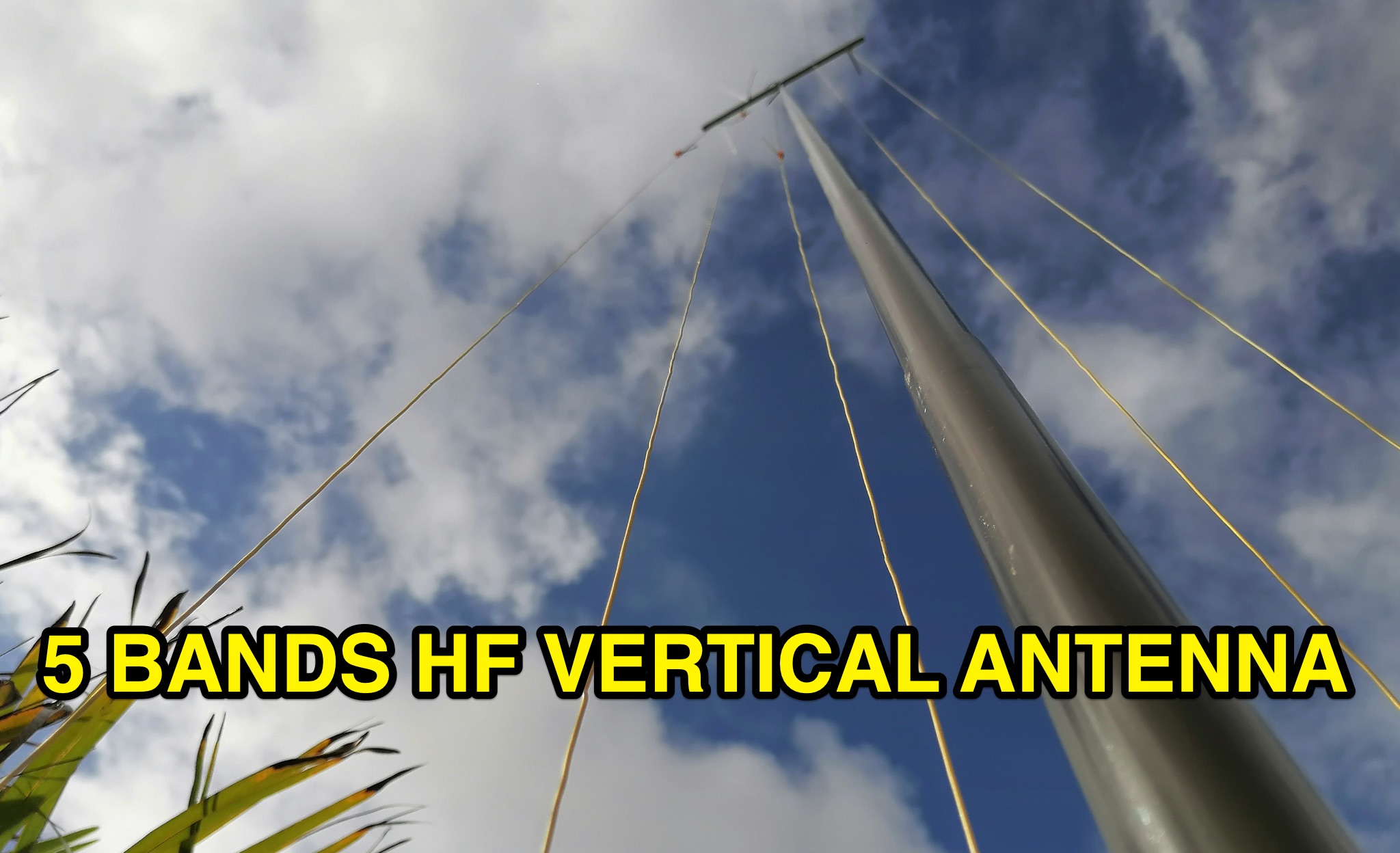 A quarter-wave vertical antenna design for HF operation offers a practical solution for radio amateurs seeking a compact and efficient multi-band radiator. This project details the construction of a 5-band HF vertical, drawing inspiration from established commercial products such as the _DX COMMANDER_ and the MV6. The design emphasizes ease of assembly and disassembly, making it suitable for portable operations or installations with limited space. The article provides insights into various construction methods and offers practical tips for building a robust yet lightweight antenna. It highlights the benefits of a vertical configuration for DX contacts, particularly on the lower HF bands, and discusses real-world performance observations. The antenna is designed to cover multiple HF bands, providing versatility for various operating scenarios. Operators can achieve significant DX results with this type of antenna, often comparable to more complex arrays, especially when deployed with an effective ground system. The project aims to empower hams to build a capable antenna without significant financial outlay.
 -
 The MCP-F6/F7 software facilitates memory channel and menu data creation for the Kenwood TH-F6A, TH-F7A, and TH-F7E transceivers. It operates on _Windows_ XP (SP3+), Vista (SP2+), Windows 7 (RTM+), Windows 8 (RTM+), Windows 8.1 (RTM+), Windows 10, and Windows 11. System requirements include a CPU faster than the OS recommendation, RAM exceeding the OS recommendation, and **2 MB** of free hard drive space. Display resolution must be XGA (1024 x 768) or higher. Connectivity to the transceiver requires an optional PG-4Y (RS-232) or KPG-22U (USB 2.0) programming cable. The KPG-22U cable necessitates a virtual COM port driver installation. The software supports COM1 through COM20 for RS-232 communication. Installation requires administrator privileges and involves executing "setup.exe" from the extracted MFX101.zip archive. Uninstallation is performed via the Control Panel's "Uninstall a program" function or by re-executing "setup.exe." Created data files are not removed during uninstallation and require manual deletion. The software version is **1.01**. DXZone Focus: Kenwood TH-F6 F7 | Memory Management | Windows | RS-232
 -
 Constructing a compact, two-band magnetic loop antenna for HF operation, especially from constrained locations like a balcony, presents unique challenges. OK1FOU's design, inspired by DJ3RW's 50 MHz loop, addresses these by employing an unusual side-fed configuration and placing the symmetric, two-section variable tuning capacitor at the bottom of the loop, directly connected to the coax shield. The article provides specific material recommendations, including two 1-meter wooden pales and about 3 meters of thick loudspeaker cable, noting the high current (60A at 100W) in the loop. Construction steps detail forming two turns with a 5 cm gap, using a GDO to pre-tune the open loop to a frequency slightly above the desired highest band, and then integrating the tuning and coupling capacitors. For 10/14 MHz, an open loop resonance of 16-17 MHz is suggested. Practical experience with the 10 MHz band from a third-floor balcony in Prague (JO70GC) shows a 1:1 SWR across most of the band without an external ATU. While DX traffic was modest due to the urban environment, QSO examples with RA6WF, LA6GIA, G0NXA, and LZ1QK on 10 MHz are provided, demonstrating its operational capability.
 -
 This resource details the computer-optimized design of the _ZS6BKW_ multiband dipole, an evolution of the classic _G5RV_ antenna. It begins by referencing the original 1958 RSGB Bulletin article by Louis Varney G5RV, explaining the operational principles of the G5RV's flat-top and open-wire feedline on 20m and 40m, noting its impedance transformation characteristics for valve amplifiers of that era. The article then transitions to the rationale for optimizing the design for contemporary solid-state transceivers requiring a 50 Ohm match. The core of the project involves using computer modeling to determine optimal lengths for the flat-top and matching section, aiming for a VSWR of less than 2:1 on multiple HF bands. It discusses the process of calculating feedpoint impedance based on antenna length and frequency, referencing professional literature from Professor R.W.P. King at Harvard University. The analysis also considers the characteristic impedance (Z(O)) of the open-wire line, identifying a broad peak of adequate values between 275 and 400 Ohms. Specific design parameters for the improved ZS6BKW are presented, including a shorter flat-top and a longer matching section compared to the original G5RV, with a velocity factor of 0.85 for the 300 Ohm tape. The article confirms acceptable matches on 7, 14, 18, 24, and 28 MHz bands when erected horizontally at 13m, and also discusses performance in an inverted-V configuration, noting frequency shifts. The author, Brian Austin ZS6BKW, emphasizes the antenna's suitability for modern 50 Ohm coaxial cable without a balun.
 -
 LOGvrr, a **freeware logging software** developed by IN3VRR, provides amateur radio operators with essential tools for managing their contacts. The resource details various downloadable components, including the core LOGvrr application, an international callbook with approximately 1.8 million callsigns, and utility programs for installation and data conversion. It supports functionalities like logging QSOs, managing awards, and interfacing with PacketCluster systems, with specific instructions for installation on Windows operating systems, including compatibility notes for Windows 10 and 11 using Hyper-V or DOSBOX. The site also offers external tools and documentation, such as the FAQ_VRR.PDF manual which covers installation, printer configuration, ADIF conversion, and Packet setup. It references third-party software like Mercurio and BV QSL Management for QSL printing, and ADIF2QSL for label printing, highlighting LOGvrr's ability to export QSOs in **ADIF format** for integration with services like LoTW. The resource includes historical updates, with the latest core component update in August 2014, and notes on the CallBook's maintenance up to 2015.
 -
 Amateur Television (ATV) operations, particularly within the Arizona region, require dedicated resources for technical information, operational guidance, and community engagement. This club provides a focal point for hams interested in transmitting and receiving video signals on amateur bands. Members engage in local ATV repeaters, participate in technical discussions, and share knowledge on video modulation schemes, antenna designs, and station configurations. The club supports activities ranging from local simplex contacts to wider area repeater usage, fostering skill development in this specialized mode. The organization maintains a roster of club officers and offers membership opportunities to local amateurs. It also curates offsite links to other ATV resources, expanding the knowledge base available to its members and the broader amateur community. The club's emphasis on ATV helps propagate interest and technical expertise in a mode that combines traditional RF engineering with video technology.
 -
 The FTBVR5K software facilitates comprehensive memory management for the Yaesu VR-5000 scanning receiver, supporting operations such as modifying, moving, adding, deleting, masking, and unmasking individual memories. It allows for importing and exporting memory definitions via CSV files, sorting memories by frequency or name, and identifying duplicate frequencies within the receiver's configuration. The program also supports the creation and modification of bank definitions, management of PMS (Programmable Memory Scan) definitions, and adjustment of PMS scanning ranges. Additionally, users can print detailed reports of memories, banks, PMS definitions, rig settings, and S.CALL details, with visual cues like red highlighting for masked memories and yellow for the priority channel. FTBVR5K provides functionality to alter values within the VR-5000's Set and Config menus, and to change S.CALL station names and frequencies. The application operates on standard Windows PCs, including Windows XP, Vista, 7, 8, and 10, requiring an available COM port for transceiver connection, which can be a conventional serial port or a USB adapter. A minimum screen resolution of 800 x 600 is supported, with 1024 x 768 recommended for optimal usability.
 -
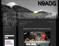 The Ameritron AL-1200 Amplifier is in current production. In its factory configuration it uses a single 3CX1200A7 (triode) tube, grounded grid configuration. Re-tubing the AL-1200 with a GS-35b with success.
 -
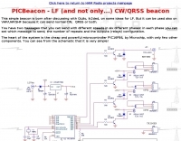 This resource details the construction of a versatile CW/QRSS beacon, designed around a Microchip _PIC16F84_ microcontroller. The project provides a flexible platform for transmitting either standard CW or very slow QRSS signals, making it suitable for LF, VHF, UHF, and SHF applications. It supports two distinct messages, each configurable for speed (from 0 to **127** WPM for CW, or up to **127** seconds per dot for QRSS) and repetition within a six-phase sequence. The core functionality relies on the PIC's EEPROM, which stores all operational parameters, including message content, transmission speeds, phase configurations, and relay control settings. This design allows for parameter modification directly via programming software like _ICProg_ without altering the main program code. The project includes a detailed schematic, a component list, and an explanation of the EEPROM memory mapping for messages, speeds, phase settings, and inter-phase delays. General-purpose outputs (OUT1, OUT2, OUT3) provide dry relay contacts for external control, enabling functions such as power switching, antenna selection, or frequency changes. A 'TRIGGER' input facilitates controlled starts or continuous free-run operation. Sample EEPROM configurations illustrate how to program specific beacon sequences, including message content and relay states.
 -
 Illustrates the specific wiring and configuration steps required to interface an SGC-230 Smartuner with an Icom IC-706 HF/VHF/UHF transceiver. The document details the necessary connections for power, control, and RF signal paths between the two devices, ensuring proper impedance matching and automatic antenna tuning functionality. It specifies the pin assignments for the IC-706's ACC socket and the SGC-230's control port, crucial for successful integration. Outlines the operational considerations for the combined system, including initial setup procedures and potential troubleshooting tips for common connectivity issues. The resource presents a clear, diagrammatic representation of the interconnections, which aids in visual comprehension of the required cable fabrication or modification. Covers the specific settings within the IC-706 menu that need adjustment to enable external tuner control, such as the 'TUNER' function and other relevant parameters. This ensures the transceiver correctly communicates with the SGC-230 for efficient antenna tuning across various amateur bands.
 -
 The K0RWU 75-meter mobile antenna design features a 7.5-foot overall length, incorporating a 2.5-foot loading coil wound with #20 enamel wire on a 1/2-inch fiberglass rod, subsequently covered with 1/2-inch shrink tubing to increase diameter to 3/4 inch. This configuration achieved resonance at 3965 kHz with a 5-foot stainless steel whip. The antenna integrates a matching transformer, identified by larger turns near the PL259 connector, and is constructed using a modified Radio Shack CB antenna base. Construction involves drilling and epoxying a 1/2-inch fiberglass rod into a PL259 connector, feeding #20 enamel wire through the rod, and winding 17 turns of #18 matching coil wire between the PL259 sleeve and the center feed point. The main loading coil fills the 2.5-foot rod section. The design allows the antenna to bend for garage clearance and emphasizes maintaining a 50-ohm feed impedance to prevent vehicle electrical damage. The author also discusses experiences with a Yaesu ATAS-100 motorized antenna and a 10-meter antenna project, noting issues with auto couplers and the ATAS-100's performance on 17 meters. Future modifications considered include adding a small servo for band spreading and increasing the fiberglass rod length for a 3-foot loading coil to improve bandwidth. The antenna's sharp tuning, between 3960 kHz and 3970 kHz, necessitates careful adjustment of coil turns for optimal VSWR.
 -
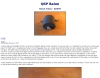 The QRP choke balun described utilizes a high permeability ferrite rod and RG-174 coax, aiming to present high impedance to common-mode currents across the HF spectrum. The construction involves winding as many turns of RG-174 as possible around the ferrite rod, then encapsulating the assembly with hot glue. This design prioritizes maximizing inductance to suppress unwanted shield currents, particularly in unbalanced antenna configurations. While the balun's effectiveness is subjectively reported as good, a potential design consideration involves the dielectric properties of the hot glue. This material could increase turn-to-turn capacitance, potentially reducing the balun's performance at higher HF frequencies, though this specific aspect has not been formally tested by the author, _AA5TB_. The project serves as an illustrative example of a practical, junk-box construction rather than a rigorously engineered solution. Photographs detail the evolution of the balun, from the initial winding process to its integration within a _B&W dipole center insulator_ and final camouflaged assembly.
 -
 The Classic Multiband Dipole Antenna QST article. The open-wire feed line dipole antenna is easy to install and offers surprising performance on several bands. You can install it in almost any configuration; it does not have to be strung in the traditional horizontal flat top
 -
 Operating a ZS6BKW antenna often involves understanding its lineage from the _G5RV_ design, with specific modifications by ZS6BKW to optimize performance on several bands. Through computational analysis and field measurements, the antenna's dimensions were refined to allow operation on 10, 12, 17, 20, and 40 meters without an antenna tuner. For 80, 30, and 15 meters, a tuner is necessary, though efficiency on 30 and 15 meters is noted as not particularly high. The physical configuration consists of two 13.755-meter radiating elements fed by a 12.20-meter section of 450-ohm ladder line. Tuning the antenna on the 20-meter band is critical, and any deviation in the ladder line's characteristic impedance necessitates recalculating the element lengths. The design is also referenced in the 12th edition of _Rothammel's Antennenbuch_, page 219. Proper common mode current suppression is crucial at the transition from ladder line to coaxial cable. This can be achieved with a common mode choke, such as several turns of coax wound into a coil or over a ferrite toroid like an Amidon T130. While a 1:1 balun is an option, it may introduce issues.
 -
 Demonstrates the design and construction of a 9-element Yagi antenna for the **70 cm band** (432 MHz), based on the DK7ZB concept. The resource details EZNEC+ calculations for a single antenna, providing gain, sidelobe suppression, and front-to-back ratio figures. It also presents a comprehensive analysis of stacking two such antennas, including optimal stacking distance (1000 mm) and the resulting performance enhancements for the stacked array, such as an increased gain of 17.03 dBi. The article includes detailed drawings, wire file dimensions in millimeters, and azimuth/elevation plots for both single and stacked configurations. Practical construction steps are documented with original photographs, illustrating element mounting, the **28 Ohm matching system** using two quarter-wave 75 Ohm transmission lines, and the critical N-connector wiring. It also covers the iterative process of fine-tuning the driven element length to achieve a return loss of 20 dB, validating the EZNEC+ simulation results with actual measurements.
 -
 Presents the mechanical and electrical specifications for a 5-element Yagi beam antenna designed for the 6-meter band. The resource details element lengths, spacing, and boom dimensions, specifically utilizing _EMT conduit_ for construction. It includes a diagram illustrating the element layout, a coaxial balun connection, and a reported SWR curve, providing a practical blueprint for hams to replicate the design. The design achieves a reported SWR of **1.1:1** at 50.125 MHz, indicating efficient impedance matching across the primary 6-meter DX window. The boom length is specified at 2.44 meters (8 feet), with element lengths ranging from 2.87 meters for the reflector to 2.59 meters for the director 3. This configuration suggests a gain figure typical for a 5-element Yagi, likely in the range of **9-10 dBi**, making it suitable for local and sporadic-E DX contacts.
 -
 For radio amateurs seeking compact and efficient antenna solutions, particularly for restricted spaces or noise reduction, HF loop antennas present a viable option. This resource compiles several articles from the ARRL, detailing the theory, design considerations, and practical construction of various loop configurations. Topics include small transmitting loops, receiving loops, and multi-band designs, often emphasizing their performance characteristics such as directivity, bandwidth, and impedance matching. The collected articles provide insights into the comparative performance of different loop geometries, such as circular versus square loops, and discuss the impact of conductor size and tuning methods on efficiency. Practical applications are explored, including their use in portable operations, stealth installations, and urban environments where noise mitigation is critical. The content often includes construction diagrams, parts lists, and performance data derived from modeling or field tests, enabling hams to replicate or adapt the designs for their specific operating conditions.
 -
 A Moxon rectangle antenna design for the 11-meter band is presented, offering a compact and lightweight solution for directional HF DX operation. This two-element parasitic array, popular among amateur radio enthusiasts, provides considerable directional gain and lower noise on horizontal polarization. The design is suitable for both 27 MHz Citizens Band (CB) and the lower portion of the 28 MHz amateur radio band, making it versatile for operators interested in either service. Construction can utilize materials like bamboo, squid poles with wire elements, or aluminum tubing on a central boom. The article includes a plan view diagram with specific dimensions (A-E) in centimeters and inches for building the antenna, such as a 392.09 cm (154 3/8 inch) driven element. The Moxon configuration inherently presents a 50 Ohm load to the transceiver, often eliminating the need for an external matching unit or balun. Performance data for an antenna mounted at approximately 30 feet indicates a gain of 10-11 dBi and a frequency range of 27.300 MHz to 28.300 MHz. The design is noted for its excellent front-to-back rejection, with tested signal drop-offs from S5-S7 to S2 when turned, demonstrating effective suppression of unwanted signals.
 -
 Presents the design and performance of a 4-element wire Yagi antenna for the 40-meter band, building upon VE3VN's earlier 3-element switchable wire Yagi. The resource details the antenna's evolution, highlighting the transition from a 3-element to a 4-element configuration and the resulting improvements in gain and front-to-back ratio. It provides specific insights into the antenna's construction and expected operational characteristics. VE3VN shares insights from field results, noting the antenna's performance on 40 meters. The discussion includes the antenna's pattern and matching characteristics, crucial for any DXer or contester looking to optimize their signal on this popular HF band. The author's experience with the previous 3-element design informs the enhancements made to this 4-element iteration. The article includes a visual representation of the antenna's current view, offering a practical perspective on its physical layout. It serves as a valuable reference for hams considering a directional wire antenna for 7 MHz operations, demonstrating a practical approach to achieving enhanced directivity and gain.
 -
 The 11-meter band, often associated with Citizens Band (CB) radio, presents unique challenges and opportunities for long-distance communication, particularly for operators interested in DXing. This group facilitates discussions and information exchange among enthusiasts who operate on this frequency, often utilizing single-sideband (SSB) modulation for improved range and signal clarity compared to traditional AM CB operations. The community provides a platform for members to share experiences, technical insights, and propagation reports relevant to 27 MHz operations. Members engage in discussions covering various aspects of 11-meter DX, including antenna configurations, transceiver modifications, and operating techniques to maximize signal propagation across continents. The forum serves as a central hub for coordinating contacts, sharing QSL information, and celebrating successful long-haul QSOs. Specific topics often include optimizing power output, reducing noise, and understanding solar cycle effects on 27 MHz. The group's activities extend to organizing virtual gatherings and promoting ethical operating practices within the 11-meter DX community. It supports both seasoned operators and those new to the band, fostering a collaborative environment for exploring the capabilities of CB radio beyond local communications.
 -
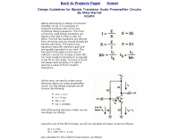 This resource, "Transistor Audio Preamplifier Circuits," offers comprehensive design guidelines for constructing **bipolar transistor** audio preamplifiers. It delves into critical aspects such as quiescent current setting, voltage gain calculation, and the impact of various component choices on circuit performance. The content provides several _schematic diagrams_ illustrating different preamplifier configurations, including single-stage common emitter and two-stage designs, alongside explanations of their operational characteristics and practical implementation considerations. The analysis extends to frequency response, noise performance, and distortion, providing insights into optimizing these parameters for specific audio applications. The resource presents calculated gain figures for various stages, demonstrating how to achieve desired amplification levels. It also discusses the importance of proper power supply decoupling and input/output impedance matching, crucial for integrating these preamplifiers into larger audio systems or ham radio transceivers. The practical application of these designs is evident in their suitability for microphone preamplifiers or general-purpose audio amplification.
 -
 Demonstrates the design and construction of a compact, portable multi-band mini-delta loop antenna, specifically optimized for /P (portable) operations from remote locations like Scottish islands. The resource covers the theoretical underpinnings of half-wave loops, contrasting closed and open configurations, and then details the application of a folded dipole principle to achieve a 50-ohm match for direct coax feed. It presents empirical formulas for calculating element lengths, considering the velocity factor of common wire types, and provides a detailed example for a 20m (14.175 MHz) version. The article includes a comprehensive table of dimensions and allowances for a five-band (20m, 17m, 15m, 12m, 10m) mini-delta beam, along with construction hints for the central support and balun. It specifies a 1:1 trifilar balun wound on a ferrite rod and describes the antenna adjustment process using an _MFJ-259B Antenna Analyser_. Initial test results indicate an SWR of 1:1 at resonance and a bandwidth of approximately 240 kHz on 20m, even at a low height of five feet above ground. The distinctive utility lies in its focus on a practical, easily deployable beam antenna for portable DXing, offering a viable alternative to more complex or larger arrays.
 -
 The W4NFR 40-meter mobile vertical antenna project details the construction of a mobile antenna system, drawing inspiration from a July 2011 QST article by VE6AB. The design simplifies the top hat by integrating an 8-spoke top hat from Tar Heel Antenna. The resource outlines the tuning process, which involves adjusting the L1 coil for the desired band segment and then fine-tuning SWR with an L2 coil at the feed point. The author achieved a 1:1 SWR at 7.150 MHz with this configuration. The project includes specific instructions for adding anti-sway supports to ensure stable operation and reduce physical stress on the ball mount during vehicle motion. Visual aids such as drawings of the 40-meter mobile antenna, detailed views of the coil and top hat assembly, and an illustration of the ball and spring mount are provided to guide the builder through the construction and installation phases. The content focuses on practical implementation and tuning for optimal performance on the 40-meter band.
 -
 This article presents a technical investigation into spurious emissions from the Yaesu FT-847 transceiver when operating on the 70MHz (4-meter) band. The author discovered significant problems with both factory "UK spec" and modified units. Spectrum analysis revealed that when transmitting at 70.2MHz, the radio produces numerous spurious signals, with the most prominent emission at 45.6MHz measuring only 3dB below the fundamental frequency. The study also documents poor power efficiency on 4m (10.3% at 30W output) compared to 6m operation (23.5% at 30W). Tests verified that jumper configurations had no effect on filter selection. The author warns that using these radios on 4m may violate license conditions due to excessive spurious emissions.
 -
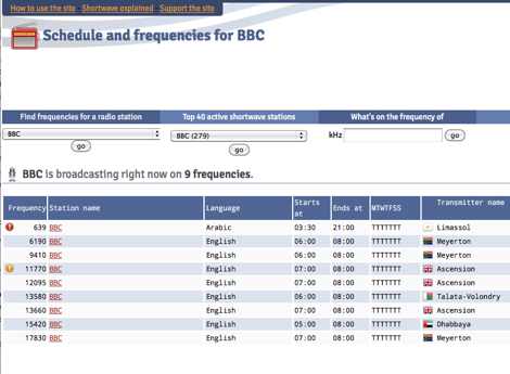 Presents a dynamic, searchable database of shortwave broadcast schedules from around the world, enabling users to locate active stations or plan listening sessions based on scheduled transmission periods and frequencies. The resource details specific station names, such as _Radio Habana Cuba_, _Deutsche Welle_, and _All India Radio_, alongside their operational times and assigned kilohertz frequencies. It also incorporates a distance calculator, which leverages geographical coordinates to estimate propagation paths, though it notes occasional data inaccuracies leading to transmitters appearing in oceanic locations. The platform's development log highlights continuous updates, including the integration of new seasonal schedules like "A24 frequencies" and "B23 schedule," reflecting the fluid nature of shortwave broadcasting. It documents challenges with geolocation services, particularly concerning Google API changes that impacted distance calculations and required user-side browser configuration adjustments for optimal functionality. The site owner, VAXXi, frequently communicates these technical adjustments and database updates, often acknowledging user contributions and donations. Distinctively, the resource provides a historical perspective through its update archives, illustrating the evolution of shortwave listening over more than a decade since its inception in 2011. It also mentions specific events, such as the BBC adding shortwave broadcasts for Ukraine on 5875 kHz and 15735 kHz, demonstrating its responsiveness to global events impacting broadcast schedules. The site's commitment to user feedback is evident in its bug reporting and feature request mechanisms, contributing to its ongoing refinement.
 -
 The **2M Moxon antenna** design presented operates at 144 MHz, providing a compact, directional solution for VHF communications. Construction involves aluminum tubing for the elements, with specific dimensions for the driven element and reflector to achieve optimal performance. The design aims for a good front-to-back ratio and a relatively low SWR across the 2-meter band, making it suitable for portable or fixed station use where directivity is beneficial. Element lengths are critical for proper resonance and pattern. The driven element measures approximately 38.5 inches, while the reflector is slightly longer at 40.5 inches. Spacing between the elements is 12 inches, forming the characteristic Moxon rectangle. This configuration yields a gain of about 5.5 dBi and a front-to-back ratio exceeding 20 dB, which is advantageous for reducing interference from unwanted directions. Feedpoint impedance is close to 50 ohms, allowing direct connection to coaxial cable without complex matching networks. The antenna's lightweight structure, typically under 2 pounds, facilitates easy deployment and rotation, making it a practical choice for field operations or as a compact home station antenna.
 -
 The Icom IC-746 is quite a popular HF/VHF multimode transceiver which has one shortcoming in its standard configuration when used to operate modes requiring good medium-term frequency stability.
 -
 The Russian Internet Callbook, hosted at krasnodar.online.ru, offers a specialized lookup service for amateur radio callsigns within the Russian Federation. This online tool is designed to assist DXers and contesters in identifying contact information for Russian stations. The resource functions as a digital callbook, allowing users to search for specific callsigns and retrieve associated data, which is crucial for QSLing and verifying contacts. While the concept is to provide a comprehensive database for Russian amateur radio operators, the current status indicates a configuration issue, as the domain krasnodar.online.ru points to the server but the site itself is not configured. This suggests the service may be inactive or undergoing maintenance, impacting its utility for callsign lookups. The original intent was to serve as a key _DX resource_ for the region.
 -
 Video demostrantion of N1MM contesting software use and configuration
 -
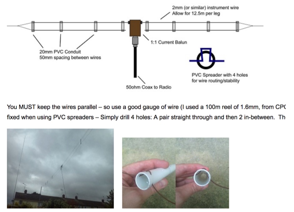 A short dipole wire antenna for 40 meters band. It is a folded dipole that do not make use of coils and can be used either in horizontal or inverted V configuration
 -
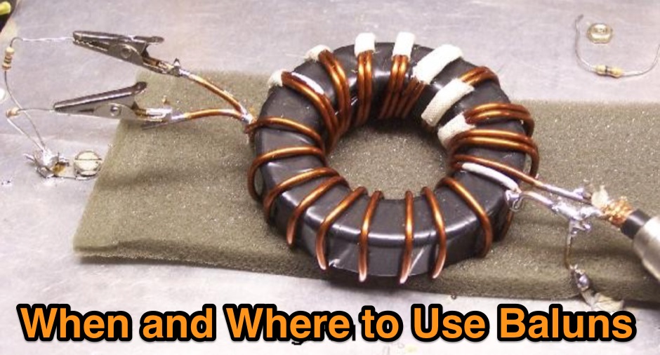 The document provides a comprehensive overview of baluns, which are devices used to connect balanced loads, like dipole antennas, to unbalanced inputs, such as coaxial cables. It covers various types of baluns, including voltage and current baluns, and their design, construction, and testing. The text discusses the importance of baluns in preventing RF currents on coax shields and their applications in Ham radio setups. It also includes practical advice on selecting and using baluns based on antenna impedance and power ratings, along with detailed performance evaluations and construction tips for different balun configurations.
 -
 This online guide details the microphone pinout for the Kenwood TR-7950 transceiver, specifically addressing the wiring configuration for a dynamic mobile microphone with a **500 Ohm** impedance. It provides a pin-by-pin breakdown for the 6-pin microphone connector, identifying the function of each active pin. The resource specifies that Pin #1 is for the microphone audio (white wire), Pin #2 controls the _PTT_ (black wire), Pin #3 activates the memory down function (blue wire), and Pin #4 controls the memory up function (red wire). Pin #6 is designated as the ground connection, while Pin #5 remains unused in this configuration. The document focuses on the physical wiring necessary to restore microphone functionality to the Kenwood TR-7950, a transceiver capable of **45 watts** output on the _2m band_. It directly addresses the technical challenge of re-establishing correct electrical connections after microphone wires have been disconnected from the connector. The information facilitates proper microphone operation for simplex QSOs and other voice communications. DXZone Focus: Online Guide | Microphone Pinout | Kenwood TR-7950 | PTT Wiring
 -
 The GW3YDX Super Moxon antenna design improves upon the standard Moxon Rectangle by incorporating additional directors in a rectangular configuration, yielding enhanced directivity and gain. For the 6m version, modeling with 4NEC2 and EZNEC+ indicated a 3dB gain increase and a 26.5dB front-to-back ratio, with VSWR below 1.5:1 between 50.0 and 50.3MHz when optimized for 50.1MHz. This design achieves a narrower -3dB power point beamwidth of 60° compared to the original Moxon's 80°, contributing to better QRM rejection. The boom length for the enhanced design is just under 2m, approximately double the original Moxon's, with no increase in wingspan. Construction details include tubing lengths for 6m, 4m, and 2m versions, with specific dimensions provided for elements A through M, measured to tubing centers. For instance, the 6m version uses a 2160mm element A and a 2140mm element H. The design maintains a 50-ohm feed impedance, with practical models showing VSWR plots consistent with simulations after minor adjustments to driven element lengths. The article also references Moxgen software for initial Moxon parameter calculation and NEC/EZNEC model generation. The 2m Super Moxon version measures approximately 30" x 25", demonstrating the compact nature of the design across different VHF bands. The article highlights the antenna's performance in real-world DX contacts on 6m, achieving contacts with over 80 stations in the USA from a modest QTH.
 -
 A circuit which had been used in many other application before. The configuration described here is optimized for IPHONE/radio operation.
 -
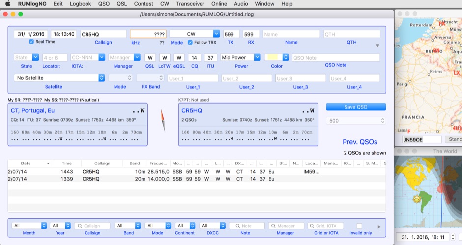 For macOS users engaged in amateur radio operations, a robust logging solution is essential for tracking QSOs, managing contest entries, and handling QSLs. RUMLog addresses these needs by providing a fully featured logbook program designed specifically for the Apple ecosystem. It integrates capabilities such as transceiver control for popular Icom, Elecraft, Yaesu, and Kenwood rigs, CW keyer interfacing, and real-time DX cluster monitoring. The software also includes mapping functions, callsign checking, and extensive import/export options for various log data formats. RUMLog's design supports both general logging and specialized contest operations, offering tools for efficient entry and submission. Its QSL handling and printing utilities streamline the confirmation process, a critical aspect for award pursuits like _DXCC_. The program's ability to interface with a wide array of transceivers via _Hamlib_ or proprietary protocols ensures broad compatibility, allowing operators to leverage its features across different station configurations. The free availability of RUMLog makes it an accessible option for macOS-based hams seeking a powerful logging utility.
 -
 The Resonant Feedline Dipole (RFD) HF antenna design utilizes a single piece of coaxial cable and a stranded wire section, forming a 1/4-wavelength radiator. This configuration, based on a 1997 ARRL Handbook design (page 20.17), functions by RF traveling on the inside of the coax shield and returning on the outside, creating the second half of the dipole. A choke wound into the feedline prevents RF current from flowing back down the feedline. Construction details include using RG-58a/u coax for a 75m version, with a 1/4-wavelength section of stranded wire soldered to the center conductor. The document provides choke dimensions for RG-213, RG-8, and RG-58 coax across 3.5 MHz to 28 MHz, specifying cable length and number of turns. Dipole dimensions are also tabulated for frequencies from 3.6 MHz to 28.4 MHz, listing overall length and individual leg lengths. Field tests included deployment near Bryson City at 5 feet off the ground and as a sloper during WCARS Field Day in Asheville, yielding successful local and regional contacts.
 -
 Optimizing a G5RV or ZS6BKW multiband wire antenna for HF operation often involves addressing common SWR issues and understanding feedline characteristics. This resource chronicles the construction and performance evaluation of a G5RV, initially built for 80m, 40m, 15m, and 10m bands, by a newly licensed Foundation operator. The author details the selection of materials, including 3.5 mm stainless steel wire for the doublet arms and enameled copper wire for the open-wire feeder, and the initial decision to omit a balun based on common online information. The narrative highlights the initial disappointing performance, characterized by high receive noise and poor signal reports on 80 meters, despite the transceiver's internal ATU achieving a 1:1 match. This led to experimentation with a coax current balun and further research into G5RV myths, such as SWR claims and the necessity of a balun. The author then describes modifying the antenna to the ZS6BKW configuration, which involves specific changes to the doublet and feedline lengths, and integrating a 1:1 current balun wound on a ferrite toroid. The modifications resulted in improved reception and transmit performance across the bands.
 -
 The resource details the construction of a 3-element Yagi antenna specifically designed for the 6-meter band, providing coverage across 50-54 MHz. This antenna design, originally featured in _QST_ August 2007, emphasizes a short boom configuration while maintaining a wideband response. Key specifications include a 50 Ohm SWR of less than 2:1 across the entire band, achieved through specific element lengths and spacing. The design utilizes aluminum tubing for elements and boom, with detailed dimensions provided for the driven element, director, and reflector. Performance characteristics indicate a forward gain of approximately 7.5 dBi and a front-to-back ratio of 18 dB at 50.125 MHz, according to _NEC2_ modeling. The antenna's compact size, with a boom length of 1.83 meters (6 feet), makes it suitable for portable operations or installations with limited space. Construction involves standard amateur radio workshop tools and materials, with a gamma match for impedance transformation to 50 Ohms. The design prioritizes ease of construction and repeatable performance for the 6-meter enthusiast.
 -
 Optimizing the ZS6BKW antenna for full HF band coverage often requires specific modifications beyond its standard configuration. This resource details several enhancements, beginning with a simple series capacitor to improve 80m SWR, a technique W5DXP found effective for permanent installation due to its minimal impact on higher bands. Further improvements include a 10-inch parallel open stub for 10m resonance, shifting the frequency to 28.4 MHz with an SWR of approximately 1.8:1, a practical solution for Technician class operators. The document then explores a switchable matching section, adding or subtracting one foot of ladder line at the 1:1 choke-balun, which significantly impacts higher frequency bands and eliminates the need for a tuner on 17m. W5DXP's _AIM-4170D_ antenna analyzer measurements confirm these effects. More advanced modifications involve a parallel capacitor for further 80m SWR reduction, requiring remote switching for multi-band operation, and relay-switched parallel capacitors at specific points on the 450-ohm matching section to achieve low SWR on 60m, 30m, and 15m. These detailed steps, including _Smith chart_ analyses for the challenging bands, aim to transform the ZS6BKW into a truly all-HF-band antenna, reflecting W5DXP's practical experience in antenna tuning.
 -
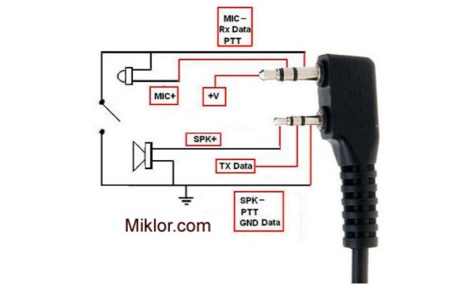 The resource provides specific technical details for Baofeng UV-3R and UV-5R series handheld transceivers, illustrating various hardware configurations. It presents a detailed _speaker microphone pinout_ diagram for multiple brands, including Baofeng, Anytone, Kenwood, and Wouxun, specifying 3.5mm and 2.5mm plug connections for mic, PTT, speaker, and data lines. The page also explains the wiring for dual PTT switching, particularly for the Baofeng UV-82 series, showing how to key either the upper or lower display channel. Furthermore, it offers comprehensive schematics and construction guidance for programming cables, detailing connections for CP2102 USB-UART modules to 3.5mm and 2.5mm plugs, and providing specific configurations for radios like the BTech UV-2501/5001 and QYT KT8900. The content also addresses SMA antenna connections, clarifying SMA Female, SMA Male, and SMA RP types, and discussing issues related to extended antenna threads, suggesting solutions like using a #8 O-Ring to ensure proper contact and prevent transmitter damage. The resource includes a section on troubleshooting erratic charger behavior, attributing issues to poor contact from tension clips and offering a simple fix.
 -
 Examines the four basic components of a mobile antenna system: the antenna, coaxial cable, antenna stud, and the mount, emphasizing mount selection as the most complex decision. Modern vehicle designs, including the absence of metal rain gutters and specific trunk configurations, often preclude traditional mirror, trunk lip, ball, or gutter mounts, necessitating universal mount designs. Discusses the economic challenges of designing vehicle-specific mounts due to tooling costs versus production runs, citing exceptions like Dodge Ram hood mounts and GM truck mirror mount brackets. The article acknowledges the difficulty for manufacturers to recommend specific mounts without direct vehicle inspection, given the vast array of vehicle designs and individual installation restrictions. Advises users with mechanical aptitude to study available mounts and assess possibilities directly on their vehicle. Recommends visiting a local communications store for personalized assistance if self-assessment proves difficult, highlighting the value of expert advice to avoid performance issues or equipment damage.
 -
 TurboLog is a station management and logging program designed for amateur radio operators, providing robust database and logging functionalities. It features fully integrated support for controlling typical radio station equipment, including transceivers, packet radio TNCs, Morse and voice keyers, and digital mode terminals. The software also incorporates antenna switching capabilities and acoustic alerting, streamlining station operations for DXing and contesting. The program's utility extends to award tracking for entities like DXCC and IOTA, alongside comprehensive callbook and ham database integration. It supports log import and export, QSL label generation, and includes TNC drivers for packet radio. The trial version allows users to evaluate its extensive features before commitment, making it a versatile tool for managing complex amateur radio station configurations and operational data.
 -
 Hidden transmitter hunting, often called fox hunting or Amateur Radio Direction Finding (_ARDF_), presents a unique challenge for radio amateurs. This resource details the _PicCon_ controller, a specialized device designed to automate the transmission of signals for such events. It integrates with a standard radio transceiver, functioning similarly to a packet radio TNC, by controlling the Push-To-Talk (PTT) line and injecting audio tones or modulated CW Morse code into the microphone input. The _PicCon_ unit is field-programmable using DTMF tones received via the radio, storing all settings in EEPROM for power-off retention. Its compact design and low power consumption (a few milliamps from a 7-35VDC source) make it suitable for remote deployment. An onboard LED indicates operational status, and a push-button allows manual start/stop of transmissions without DTMF. Typically supplied as a kit, _PicCon_ includes a PCB, components, and a comprehensive manual (available in HTML, RTF, and PDF formats). The kit provides a six-conductor interface cable, but users must supply radio and power plugs due to varied configurations. Byon, _N6BG_, developed this controller, which is available from the Byonics website.
 -
 Presents a QRP AM/CW transmitter project specifically designed for the 10-meter band, utilizing a crystal oscillator and a collector-modulated AM oscillator. The design employs a 2N2219(A) transistor in a Colpitts configuration, generating 100 to 350 mW of RF output power depending on the 9-18 Volt supply voltage and modulation depth. Frequency stability is maintained by a 28 MHz crystal, with fine-tuning possible via a Ct1 trimmer capacitor for approximately 1 kHz adjustment. The resource details the RF oscillator stage, implemented with a 2N2219 NPN transistor, emphasizing frequency stability and low power dissipation. It also covers the amplitude modulation stage, managed by a 2N2905 PNP transistor, which impresses audio information onto the carrier. Selective components (C3, C4, C7, C5) enhance voice frequencies within a +/- 5 kHz bandwidth, and modulation depth is controlled by R2 and R3. The project includes a 3-element L-type narrow bandpass filter (Ct3, L3, C10) to suppress harmonics and ensure a clean output signal. The project provides a complete schematic diagram, a comprehensive parts list including specific capacitor, resistor, and inductor values, and construction notes for the coils (L1, L2, L3). It also offers practical advice on enclosure requirements, suggesting an all-metal case or a PVC box with graphite paint for RF shielding. Operational parameters such as current draw (27mA@9V to 45mA@16V) and input impedance (50 Ohms) are specified, alongside guidance on antenna matching and the importance of a valid amateur radio license for 10-meter band operation.
 -
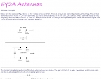 Configurations of the vertical antenna arrays used at 6Y2A
 -
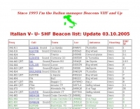 The _Italian VHF Beacons_ resource provides a detailed listing of active and QRT amateur radio beacons operating across VHF, UHF, and SHF bands within Italy. Each entry specifies the beacon's callsign (e.g., IQ1SP/B), operating frequency (e.g., 144.411 MHz), QTH locator (e.g., JN44VC), effective radiated power (ERP) in watts, and antenna configuration (e.g., Big Wheel, 4x Dipole, Yagi). This data is crucial for radio amateurs involved in propagation studies, equipment testing, and long-distance (DX) communication on these higher frequency bands, offering fixed signal sources for monitoring. This compilation, last updated in October 2005, serves as a historical snapshot of Italian beacon activity. For instance, it lists several 144 MHz beacons with ERPs ranging from **0.1W** to **10W**, and higher frequency beacons such as I8EMG/B on 1296.880 MHz and I3EME/B on 24192.132 MHz. The inclusion of QRT (Quiet Radio Teletype) status for many entries indicates the dynamic nature of beacon operations over time. Users can utilize this information to identify potential signal sources for band openings or to calibrate their receiving equipment against known transmissions.
 -
 Demonstrates the construction and implementation of a **two-element phased vertical array** for 40 meters, utilizing _Christman phasing_ techniques. The author, W4NFR, details the process from building individual 1/4-wave aluminum verticals to integrating them into a phased system. The resource covers antenna spacing of 32 feet, elevated radial design, and the critical steps for tuning each vertical to achieve a 1.1:1 SWR before combining them. It also provides insights into calculating precise coax lengths for feedlines and the phasing delay line, emphasizing the use of an MFJ-269 Antenna Analyzer for verification. The finished system exhibits good front-to-back nulls, with an overall SWR ranging from 1.6:1 to 2.2:1, which is managed by an antenna tuner. The project includes detailed photos of the relay box, showing 12 VDC relays capable of handling 5KV, and the control box in the shack for switching between three different antenna pattern configurations. Static bleed-off chokes are incorporated for protection, and the construction emphasizes robust weatherproofing for outdoor elements.
 -
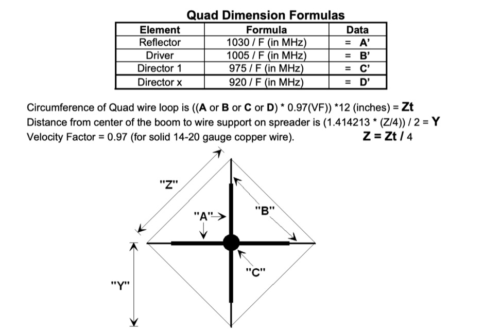 The information in this article has come from many amateur sources, the most notable was from WA6TEY (sk 1985) Ray Frost, who was a pioneer of VHF Quad designs and one of the best Southern California Transmitter Hunters. Ray built hundreds two meter quads in single and paired configurations as well as his famous mobile radio direction finding quad.