Search results
Query: gain
Links: 463 | Categories: 6
-
 Delta Loop Antenna for 15m band. This antenna is made for operating from outdoors, mainly from mobile shack. Drive to a parking you like, then build it up. Just half an hour later, you can enjoy slightly better gain than normal dipole.
 -
 Presents a crystal-controlled CW transmitter design for the 40-meter band, delivering 5 to 7.5 watts output power. The circuit innovatively employs an _IRF510_ power MOSFET in the final amplifier stage, diverging from conventional bipolar transistors. This design offers high gain, nearly 90% efficiency, and robust resistance to high SWR, allowing 30-second key-down operation into an open circuit without damage. A critical aspect is the precise adjustment of the MOSFET gate bias via a 10K trimmer pot, _R10_, to maintain quiescent current between 5 and 10 mA, preventing thermal runaway inherent to bipolar devices. The prototype was constructed on a _Radio Shack universal board_ and achieved immediate operational success. The design requires a 15-volt Zener diode to protect the MOSFET gate from overvoltage. Component sourcing information is provided, including specific crystal frequencies (7.040 MHz or 7.122 MHz) available from _Dan’s Small Parts & Kits_ or Doug Hendricks. The fixed frequency can be slightly adjusted with a trimmer capacitor. A complete bill of materials, including resistor values, capacitor types, toroid specifications, and transistor part numbers, is detailed, alongside a clear schematic diagram.
 -
 Presents a detailed construction guide for a 2-element _Moxon rectangle_ antenna optimized for the 10-meter band, designed by L. B. Cebik, W4RNL (SK). This resource demonstrates how to build a compact beam antenna using readily available hardware store aluminum tubing, fitting within a 12-13 foot width. It highlights the antenna's performance characteristics, including a gain comparable to a 2-element Yagi (11+ dBi) and a front-to-back ratio exceeding 20 dB between 28.3 and 28.5 MHz, with an SWR below 2:1 across the entire band. The design emphasizes direct 50-ohm coax connection without a separate matching system, though a 1:1 choke _balun_ is recommended. The guide provides practical advice on element construction, corner fabrication using L-stock or radius-bent tubing, and the critical side-to-side length adjustment for SWR optimization. It details the feedpoint assembly using a chassis-mounting coax connector and discusses element-to-boom plate options, including spar varnished plywood or LE plastic. The author's experience with a test model on a 20-foot mast confirms stable feedpoint characteristics and excellent performance even at lower heights. The document also includes insights into the antenna's free-space azimuth patterns, noting a broad forward lobe and significant front-to-back rejection. It contrasts the Moxon with traditional Yagis, positioning it as an effective, home-buildable alternative for compact sites or _Field Day_ operations, particularly beneficial during periods of increased 10-meter activity.
 -
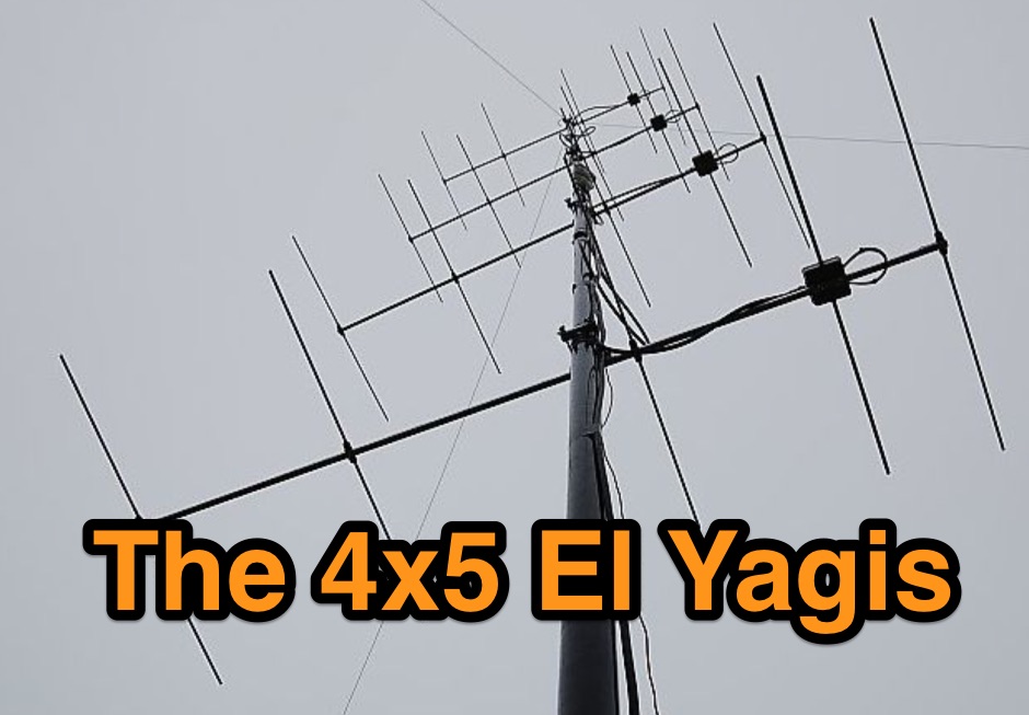 2m SSB/CW-12.5 Ohm Yagis with extrem high gain and small bandwidth. These Yagis were constructed as ultra-light, portable Yagis with extrem high gain. They have small bandwidth and are working from 144,0-144,8MHz with good SWR.
 -
 The KD6WD Moxon Antenna Project details the construction of 50-ohm two-element wire beam antennas, specifically Moxon rectangles, for the 10, 15, 17, and 20-meter bands. It utilizes AC6LA's software for critical measurement calculations (A-E) based on center frequency and wire size. Construction involves 16-gauge silver-coated copper wire, 16-foot telescoping fiberglass crappie fishing poles as spreaders in an "X" configuration, and various hub designs including aluminum tubing or PVC joints. A 1:1 current balun is used at the feedpoint, with wire nuts for connections, often achieving a 1:1 SWR across the design band. The project highlights practical applications, such as running a kilowatt into the antennas for greyline DX contacts, consistently yielding excellent signal reports. Comparisons to quad loops show 4 to 5 S-unit improvements in both receive and transmit. The Moxon design, according to L.B. Cebik's analysis, offers superior forward gain and front-to-back ratio among wire beams. The author notes a "DX-Vane" effect where a freely suspended Moxon automatically points to the strongest DX signal. Attempts at dual-band operation (17/20 meters) with a single feed were unsuccessful, reinforcing the Moxon's monoband nature, with EZNEC plots provided for a 17-meter Moxon at 30 feet.
 -
 SM0DTK's 40-meter Moxon antenna project details the construction and deployment of a wire Moxon rectangle, specifically dimensioned for the 7 MHz band. The resource outlines the use of a _Moxon Rectangle Generator_ for calculating wire lengths and the fabrication of plexiglass supports for corners and the feeding point. It describes the practical challenges of elevating the antenna to approximately **14 meters** using an aluminum tube and fiberglass rod, emphasizing the adjustment process for achieving the correct rectangular shape. The article presents comparative results against a 60-meter long-wire and a full-size 40-meter ground plane antenna. The Moxon demonstrated significant directional gain towards the west, facilitating DX contacts in the Caribbean with **100 watts**, while simultaneously reducing QRM from strong eastern European stations. The SWR was reported as perfect without the need for an antenna tuner, validating the design's effectiveness for targeted signal enhancement and interference mitigation.
 -
 Selecting an appropriate antenna system for shortwave broadcasting involves evaluating various types based on performance, cost, and operational parameters. This resource details the critical specifications for broadcast antennas, including average and peak power ratings, directivity, takeoff angle (TOA), horizontal beamwidth, and gain, emphasizing that a 100-kW transmitter requires an antenna rated for 150 kW average and 400 kW peak. It clarifies that low TOA signals travel thousands of kilometers, while high TOA is for local coverage, and nearly all modern shortwave broadcast antennas are horizontally polarized. The article explores specific antenna types, such as Log-Periodic Antennas (LPAs), which offer wide frequency ranges (e.g., 2-30 MHz) and directional patterns with 11 dBi gain, costing from $20K to over $100K for multi-curtain versions. Dipole arrays, also known as curtain antennas, are prevalent in international broadcasting, featuring steerable beams (±15° and ±30°) and mode-switching capabilities to alter TOA, with high/low pairs costing over $1 million. Fan dipoles are noted for omnidirectional patterns, smaller size, and lower cost for low-power applications, while rhombics, though simple, require resistive termination and incur several dB of I2R losses. Balun considerations are crucial, as most communications baluns are not rated for the higher average and peak powers of AM broadcast transmitters. Modern shortwave antennas utilize durable materials like Alumoweld wire rope for radiators and support elements, avoiding copper, fiberglass, or materials prone to stretching or deterioration. Feeder systems for high-power stations often require tapered-line baluns to convert 50-ohm unbalanced power to 300-ohm balanced for connection to the antenna.
 -
 Manufacture CATS antenna rotator and digital controls. Service, stock, and provide parts for top quality AMERICAN-MADE antenna rotators from companies such as Alliance, C.A.T.S., CDE/Hy-Gain, and Channel Master, both young and old.
 -
 Reducing noise to your antenna can gain your aerial performance, learn how.
 -
 Antenna Gain Explained delves into the fundamental principles behind antenna gain, a concept that often perplexes even seasoned RF engineers. The author, Marc, clarifies that antennas do not generate power but rather focus existing RF energy into desired directions, effectively reshaping the radiation pattern. He defines key terms such as _decibel (dB)_, _Antenna Gain_, and _Radiation Pattern_, emphasizing the distinction between dBD (referenced to a ½-wavelength dipole) and dBi (referenced to an imaginary isotropic antenna), noting that dBi figures are 2.14dB higher. The discussion illustrates how a standard ½-wavelength dipole's "doughnut" radiation pattern can be flattened into a "pancake" to achieve gains of 3dB, 6dB, or even 9dB by concentrating energy horizontally. Marc also explains how reflectors and directors are employed in directional antennas to further intensify radiation in a specific direction, potentially achieving gains as high as 20dB, albeit with a narrower effective angle. The concept of _Front-Back Ratio_ is introduced for directional antennas, detailing how some energy inevitably radiates to the rear due to diffraction, even with solid reflectors.
 -
 BeaconSee shows you, in real time, worldwide HF band openings on your PC. Analyses the audio signals from your radio, which is tuned to the NCDXF IARU HF beacon network and shows you the signal strength received from each of the 18 beacon transmitters as a plot of frequency spectrum against time.
 -
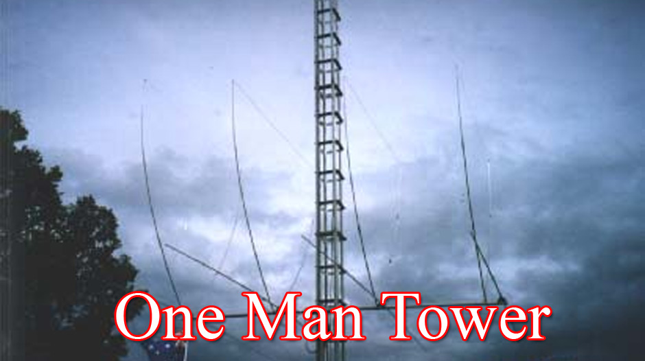 Complete tower system incorporates rotator mount, and lateral support collars. You never have to climb again - and forget the hassle of tilting over to work on large arrays. The "One Man Tower" is the strongest dmall footprint free standing self erecting tower in the world
 -
 This projects was developed as a result of experiments to become QRV on 80 meters, again, using the little balcony by SM0VPO
 -
 Perfect ground vs. poor ground. What is the difference? How does the ground influence the DX-gain?
 -
 The KD1JV "Melt Solder" Digital QRP SWR/Power Meter operates across the 160m to 6m bands, featuring 9.9-watt and 990-milliwatt power scales, a peak hold mode for SSB, and a VSWR scale from 1:1 to 9.9:1. It utilizes a _Stockton directional coupler_ wound on a single binocular core and an _Atmel AVR ATtiny26L_ microcontroller for processing. The design incorporates _W7EL diode compensation_ in a non-inverting amplifier feedback loop to address diode voltage drop and non-linear behavior at low power levels, with software corrections applied for improved accuracy, particularly at QRP power levels up to 5 watts. Construction details include parts placement, transformer winding instructions for #26 magnet wire, and calibration procedures using a 1.5V alkaline battery or an oscilloscope with a 50-ohm dummy load. Packaging options are discussed for fitting the board into an Altoids tin or a deeper Whitman’s Sampler tin, with considerations for battery life extension by adding a third or fourth battery. Accuracy tests performed at 7 MHz compare readings against a True RMS power meter based on an _Analog Devices AD8361_ chip, showing typical deviations of 0-5% across various power levels.
 -
 802.11b WLAN Waveguide Antennas Unidirectional & Omnidirectional. High gain, Simple construction by Trevor Marshall
 -
 Demonstrates an online **CW** audio decoder tool, currently under active development, designed for analyzing and decoding Morse code. Users can upload audio files containing Morse code or record live audio input via a microphone, with processing handled entirely in JavaScript using the Web Audio API. The software analyzes the audio, attempting to determine the pitch and speed, and then decodes the message, providing options to compare the decoded output against a predefined message or a perfectly timed version. The interface allows for setting optional comparison messages, character speed in WPM, and Farnsworth speed. It also features interactive charts for visualizing the audio analysis, where users can zoom with the mouse wheel and pan by dragging. Specific buttons highlight different element types such as intra-character space, inter-character space, extra elements, missing elements, and replaced elements, aiding in detailed signal analysis. Built-in test files are available for immediate analysis, allowing users to quickly evaluate the decoder's performance. The tool is noted to work with specific browsers and is presented as a testing platform for user feedback, indicating ongoing refinement of its decoding algorithms and user interface.
 -
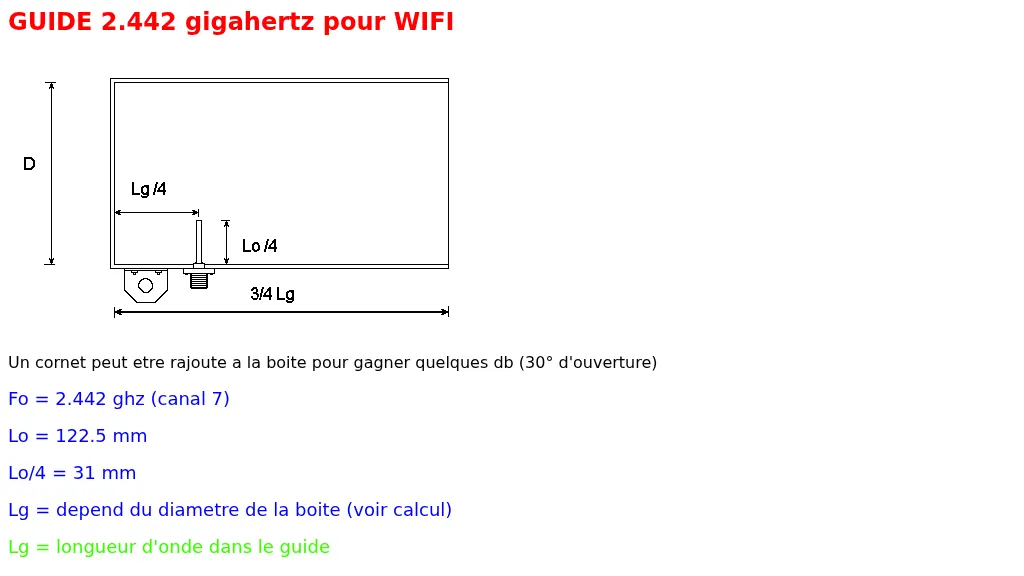 Demonstrates the construction of a 2.4 GHz horn antenna, specifically designed for WiFi applications, with the potential to add several dB of gain. The resource focuses on the critical dimensions and calculations required for proper operation, including _wavelength_ (Lo) and guide wavelength (Lg) based on the operating frequency (Fo) of 2.442 GHz, corresponding to channel 7. The guide provides a table of European WiFi frequencies, ranging from 2.412 GHz to 2.477 GHz, highlighting the specific channel 7 as the design target. It details how the length of the waveguide (Lg) depends on the diameter of the enclosure, offering a practical approach to antenna construction. This project outlines the necessary measurements like Lo/4 at **31 mm** and provides a link to an external calculator for further design specifics. The horn design aims for a 30-degree beamwidth, making it suitable for focused signal transmission or reception.
 -
 The **NW3Z** optimized wideband antenna designs, originally presented at Dayton 2001, detail Yagi configurations for the 20-meter, 15-meter, and 10-meter amateur radio bands. This resource provides access to the design files, likely containing critical parameters such as element spacing, element lengths, and boom dimensions, which are essential for replicating these directional antennas. The designs focus on achieving wide bandwidth, a desirable characteristic for contesters and DXers operating across a significant portion of each band. The content specifically references "nw3z-Antenna-DesignsDownload," indicating that the core information is available as a downloadable file, presumably in a format suitable for antenna modeling software or direct construction. Such files typically include **NEC models** or similar data, allowing for performance analysis and optimization before physical construction. The emphasis on "optimized wideband" suggests design considerations for SWR bandwidth and gain characteristics over a broader frequency range than typical narrow-band Yagis. The resource serves as a direct source for specific, proven antenna designs from a known amateur radio antenna designer, offering practical data for hams interested in building high-performance Yagi arrays for HF.
 -
 Examines the rationale behind L. B. Cebik, W4RNL's, consistent use of dBi for specifying antenna gain in his modeling work, contrasting it with the common practice of using dBd. The article meticulously defines decibels as relative power measurements and introduces the theoretical _isotropic radiator_ as the baseline for dBi, highlighting its utility as an unchanging constant for universal antenna comparison. It details how maximum gain in dBi allows for straightforward numerical comparisons between antennas, while also emphasizing the importance of considering other factors like horizontal beamwidth, vertical beamwidth, and elevation angle of maximum radiation for a complete performance picture. The resource then critically analyzes the concept of dBd, categorizing it into _dBd-I_ (ideal dipole), _dBd-RM_ (real modeled dipole), and _dBd-RR_ (real range dipole), exposing the ambiguities and inconsistencies inherent in these varied definitions. W4RNL argues that the lack of standardized protocols for dBd measurements, particularly in real-world test ranges, makes direct comparisons problematic without extensive supplementary data on test conditions and comparison antennas. He illustrates how these complexities often obscure rather than clarify antenna performance. Ultimately, the article advocates for dBi as the more robust and unambiguous standard for antenna modelers, especially when comparing diverse antenna types where a dipole is not a relevant benchmark. It acknowledges that range testers may continue to use dBd-RR due to practical limitations, but stresses the critical need for detailed test protocols to ensure meaningful results. The discussion underscores the ongoing challenge of correlating real-world antenna measurements with theoretical modeling.
 -
 A woktenna. The collector and stand collapses in seconds, is aimable, portable, and gave terrific gain. This is a great little setup for a laptop on the go trying to get the distant wifi access.
 -
 The K5OE 2-meter vertical mobile antenna design, detailed in this resource, employs a 3/8-wavelength vertical section complemented by four shortened radials, forming an off-center-fed vertical dipole. This configuration creates a self-contained lower half, enhancing efficiency compared to traditional 1/4-wave monopoles relying on vehicle bodies for a ground plane. The article specifies construction using PVC components, 10-gauge insulated wire for elements, and provides precise dimensions in both inches and centimeters for the 25-3/16" (64 cm) vertical and 7-3/16" (20 cm) radials. Performance data indicates an honest 3 dBi of gain at 6 feet elevation (2 dBi free-space), with a pattern favoring the horizon, suitable for Low Earth Orbit (LEO) satellite communications. At 20 feet high, the same antenna exhibits almost 6 dBi of gain, with a nominal 50 Ohm feedpoint impedance at 146.850 MHz. Tuning instructions involve trimming element lengths, with the author achieving a 1.2:1 SWR by pruning the mast to 24-3/4" and radials to 7". The resource highlights the antenna's effectiveness for mobile LEO satellite uplinks, particularly at low elevations, and its suitability for fixed, mobile, or portable operations. The flexible wire elements allow for easy folding, making it a practical choice for backpacking. The original design by K5OE was previously hosted on aol.com.
 -
 Broadband dipole antenna, needs an antenna tuner but can reach 3db gain over dipole
 -
 The ARRL ANTENNA Vol 5 COMPENDIUM features an article detailing two portable 6-meter antennas: a 2-element quad and a 3-element Yagi with telescoping elements. The 2-element quad exhibits a measured gain of **4.2 dB** over a dipole, while the 3-element Yagi achieves **5.8 dB** over a dipole. Both designs prioritize ease of construction and rapid assembly/disassembly for portable operations. Specific dimensions are provided for a 3-element 6-meter quad using #14 bare copper wire. The reflector element diameter is 6.2958 meters, the driven element 6.125 meters, and the director 5.8547 meters. Element spacing is 0.9398 meters between reflector and driven, and 1.1684 meters between driven and director. The SWR is under _1.26:1_ from 50 to 50.4 MHz, with a feed point impedance of 48.75 -j0.13 Ohms at 50.2 MHz, suitable for direct 50 Ohm coax feeding with a current _balun_.
 -
 The QM7 antenna is a simple 7 elements Yagi with 3.70 m boom length for the lower 144 MHz SSB/MGM band, used it mainly for Sporadic-E and MS contacts. It exhibits a forward gain of 11.35 dBd; i.e. 13.5 dB forward gain over the isotropic radiator, while the F/R is about 12.5 dB
 -
 One common challenge for radio amateurs involves interpreting antenna gain specifications, which are often presented using various units like dBi or dBd. This article clarifies the distinctions between isotropic, dipole, and effective radiated power (ERP) gain measurements, providing a foundational understanding for selecting appropriate antennas. It details how dBi references an isotropic radiator, dBd compares to a half-wave dipole, and ERP integrates transmitter power with antenna gain. Understanding these gain metrics is crucial for accurately assessing an antenna's directional characteristics and overall efficiency in a specific operating environment. The resource explains how to convert between dBi and dBd, noting that 0 dBd equals 2.15 dBi. It also touches upon the practical implications of these values in real-world antenna performance, helping operators make informed decisions about their station's radiating system.
 -
 LP-Rotor 2.0 is a standalone freeware rotator control program for use with Microsoft Windows. LP-Rotor should work with all versions of Windows from Windows 95 forward. It is designed to be used with the Hy-Gain DCU-1 or RotorEZ interfaces for Hy-Gain rotators, or the RotorCard interface for Yaesu rotators.
 -
 Constructing a **2-meter** J-pole antenna from readily available copper plumbing components offers a robust and cost-effective solution for VHF operation. This design, dubbed the "Plumber's Delight," functions essentially as a half-wave dipole fed by 50-ohm coax via a **gamma match**. It incorporates a quarter-wave copper tubing support, which, when affixed to a metal mast or tower, enhances forward power in the direction of the radiating elements. The original configuration utilized a small ceramic trimmer capacitor for the gamma match, suitable for up to 10 watts. A subsequent modification replaced this with a 50 pF variable capacitor housed in a plastic enclosure, accommodating higher RF power and improving weather resistance. The antenna elements are secured using a copper "T" fitting, and an SO-239 connector mounts directly to this fitting. Performance includes gain away from the support mast, and tuning is straightforward by adjusting the gamma match capacitor for a 1:1 SWR. The total cost for materials, excluding the capacitor and coax, can be under $10.
 -
 These omnidirectional antennas offer Horizontal polarization, and about 2.1 dbd of gain. They are much quieter than a dipole or a vertical, have a broader bandwidth and will usually out perform a dipole antenna.
 -
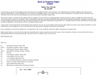 Demonstrates building a basic _VOX circuit_ to add voice-operated transmit functionality to HF transceivers that lack this feature. The design utilizes a _1458 dual op-amp_ (two 741 op-amps in one package) to amplify microphone audio and act as a comparator, driving an NPN switching transistor for PTT control. A capacitor, C2, provides the necessary delay before unkeying the PTT, with a variable resistor, R6, allowing adjustment of the VOX level for specific microphones or voices. This low-cost circuit, detailed with a full parts list, offers a practical solution for hams seeking to enhance their budget HF rigs. The author, N1HFX, provides guidance on initial setup, including advice on microphone gain and the use of headphones to prevent speaker audio from re-keying the transceiver. Modifications for adjusting delay time are also included, suggesting increasing R8 to 10K for more delay or decreasing C2 to 22µF for less.
 -
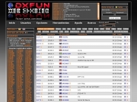 Demonstrates a **DX cluster** web service providing real-time amateur radio spot reports, propagation information, and solar data. The platform integrates features such as a gray line map, **DXCC** tracking, and a personal logbook, allowing users to manage their confirmed entities and contacts. It supports various bands from 160m to 70cm, including specific filters for modes like FT8/FT4, and offers both web and Telnet access for spotting and monitoring. The service provides graphical representations of spot reports, detailing activity across different frequency bands and modes (CW, SSB, digital). Registered users gain access to advanced functionalities, including personalized filters and tools for calculating DXCC status. The platform also includes a classifieds section and options for mobile access, catering to a broad range of amateur radio operators interested in DXing and contesting.
 -
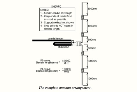 This project is about a cheap way of building a colinear antenna for VHF 145MHz, and having about 10dB more gain than that little 1/4-wave magmount
 -
 Automatic Link Establishment (ALE) is a digital signaling protocol enabling HF radio stations to automatically establish communication links, crucial for emergency and disaster relief operations. HFLINK serves as a central international resource for ALE High Frequency Communications, HF Selective Calling (SELCALL), and general HF interoperability. The platform provides extensive information on ALE operation, including frequency networks, band plans, and software like _PCALE_ for amateur radio integration. It also documents significant events such as the _HF Interoperability Exercise (HFIE)_ and the _Global Simulated Emergency Test (GlobalSET)_, which allow ham operators to gain real-world experience in interoperable HF communications, often using specific frequencies like the USA 5 MHz ALE simplex frequency 5371.5 kHz USB. The site features articles on antenna types popular among ALE users, such as autotuners and broadband antennas like the _T2FD_ and the Broadband Butterfly Terminated Dipole (BBTD).
 -
 MoxGen is a **Windows** application designed to calculate dimensions and generate antenna model files for 50-ohm **Moxon Rectangle** antennas. Users input the desired design frequency in MHz and the wire size (AWG or diameter in inches/mm), and the software outputs the precise element lengths, spacing, and overall dimensions required for construction. It also creates a .maa file compatible with EZNEC, enabling further analysis and optimization of the antenna's performance characteristics. The software provides a visual representation of the Moxon rectangle, displaying key parameters such as gain, front-to-back ratio, and SWR at the design frequency. This allows radio amateurs to quickly assess the potential performance of their proposed antenna before physical construction. The generated EZNEC model facilitates detailed pattern analysis, impedance matching, and interaction with surrounding structures, proving useful for both initial design and fine-tuning.
 -
 The BV6 50 MHz Yagis resource details the construction of two distinct Yagi antenna designs for the 6-meter band, specifically a 1-wavelength (1wl) model and a 2.1-wavelength (2.1wl) model. The 1wl Yagi, with a boom length of 5.850m, achieves a gain of **9.4 dBd**, while the 2.1wl Yagi, spanning 12.90m, boasts a gain of **11.9 dBd**. These designs adhere to a proven methodology for optimizing current slope and maintaining constant phase delay across parasitic elements, ensuring high gain per boom length and an _excellent pattern_. Both designs target a 50-ohm input impedance, facilitating straightforward feeding with a robust folded dipole. Final verification using NEC-II software confirmed the antennas' exceptional stacking capabilities, yielding stacking gains exceeding **5.8 dB** for a 2x2 array with minimal mutual detuning. The resource provides common mechanical data, including boom and element diameters, and specifies element lengths corrected for boom diameter. While the original _DUBUS Technik V_ publication contained incorrect element lengths, this resource provides the accurate dimensions for proper construction, emphasizing the use of readily available materials for cost-effective amateur radio deployment.
 -
 NuMorse 2.20.0.0 for Win 7/Win 8/XP/Vista/Win 10 A complete rewrite of the original NuMorse used by thousands of radio amateurs to gain and upgrade their licenses. NuMorse offers an intermediate feature set that is somewhere between the lean and mean NuCode program and the vast array of features supported by NuMorse Professional. But NuMorse is no cut-down program. It has several unique features not found in other Nu-Ware products as well as a compact and intuitive set of controls that you will be able to learn quickly.Product is no more developed and out of support.
 -
 Simple gain antennas for the beginner, a 2 element HF yagi antenna
 -
 VE7CA reprint an interesting article taken from arrl antenna compendium. Two elegant practical and portable 6-meter gain antennas, a two-element quad and a tree-element Yagi antenna for 50 Mhz-6 meter band
 -
 This resource presents a detailed analysis of the W6NL 2-element 40-meter **Moxon Yagi** antenna, covering its design, construction, and measured performance characteristics. It outlines key specifications such as a free-space gain of 6 dBi, 11 dBi at 70 feet, and a direct 50-ohm feed. The document highlights the antenna's physical attributes, including 52-foot elements, a 27-foot boom, and a weight of 75 pounds, engineered to withstand 125 mph winds. Modeling was performed using **AO6** and K6STI software, with a focus on the unique functions of the transverse tip elements for Moxon coupling, physical balance, efficient capacitive loading, and reduced wind load. The presentation includes comparative data, showing the Moxon's superior front-to-back (F/B) ratio and wider bandwidth compared to traditional loaded Yagis. Performance graphs illustrate the SWR, gain, and F/B across the entire 40-meter band (7.0-7.3 MHz), comparing measured results against calculated values. Azimuth and elevation patterns demonstrate high F/B, with the antenna's pattern matching that of a full-size 3-element Yagi on a 30-foot boom. It also notes a gain difference of 1.5 dB down relative to a K3LR 4-element Yagi on a 50-foot boom, providing practical benchmarks for performance evaluation.
 -
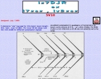 5 elements "vee" log-yagi for 10m band- boom lenght : 4mt. Gain : over 10 dBd , f/b =over 40 db (deep null) f/b= min 20dB for different polarization signals
 -
 A 40-meter reversible _Moxon rectangle_ antenna project details its construction and performance, featuring 51-foot long sides and 7.7-foot turned-in sections. The design incorporates a 16.5-foot boom, with elements spaced 1.1 feet apart, constructed from #14 covered wire. It utilizes two double-pole relays for switching between NE and SW directions, achieving F/B ratios up to 40 dB on CW and 30 dB on SSB, with distinct reflector stub settings for each mode. This antenna replaced a full-size 2-element Yagi, demonstrating comparable forward gain while offering superior F/B ratios and directional flexibility. _EZNEC_ modeling indicates only 0.2 dB less forward gain than the Yagi. The system uses no baluns, relying on half-wave feedlines and switched stubs for impedance matching. The antenna is tree-supported at 45 feet, with its effective radiation height modeled at 80 feet due to local terrain, enhancing its performance over a nearby lake.
 -
 Details the construction of a portable _Moxon_ antenna optimized for the 2-meter band, utilizing readily available materials like 6.5 mm aluminum elements and a 15x15 mm TV boom. The design emphasizes ease of assembly and portability, making it suitable for field operations. Performance specifications derived from MMANA modeling indicate a forward gain of **6.3 dBi** and a front-to-back ratio of **15 dB**. Lateral attenuation is reported at 40 dB, with a minimum SWR of 1.1 at 144.300 MHz, confirming efficient operation within the target frequency segment. The antenna is lightweight at 500 grams, quickly assembled in approximately two hours, and disassembles into a compact 40x15x8 cm package. Direct feeding with RG-58 C/U or KX-15 coaxial cable via a BNC connector simplifies deployment.
 -
 The "Largest YU Moxon" document meticulously details the design and construction of a substantial multiband Moxon antenna, primarily for 80m, 40m, and 20m operation. It presents specific design parameters derived from NEC-based simulations, including a 4-element 80m Moxon with 37 dB F/B and 7.81 dBi gain on a 47m boom, a 4-element 40m Moxon with a bidirectional pattern, and a 6-element 20m Moxon optimized for specific side lobes. The resource provides precise element lengths and spacing in meters for each band, alongside measured SWR results across the 3.650-3.800 MHz, 7.000-7.100 MHz, and 14.000-14.350 MHz segments. The construction narrative outlines the challenges and solutions encountered by the YU team, including the use of trees for support, the creation of "ugly" air-choke baluns from RG-58 cable wound on plastic bottles for each band, and the meticulous process of attaching wires to a rope boom. It documents the physical dimensions of the vineyard site (47 x 38m) and the azimuth orientation (340 degrees) chosen for the antenna. The document is distinctively useful for its practical insights into large-scale antenna deployment in a field environment, offering real-world SWR measurements and anecdotal performance reports from CQWW contest operations. It includes numerous photographs illustrating the construction process, the team members, and the finished antenna structure, providing visual context to the technical details.
 -
 The Elecraft K3, a popular HF transceiver, is often benchmarked against new market entrants. This article critically compares the Kenwood TS-590S to the K3, focusing on key technical specifications and operational aspects relevant to serious amateur radio operators. The author proposes three distinct evaluation methods: a circuit diagram comparison, an independent review analysis (referencing Peter Hart, G3SJX, in RadCom), and a real-world "ear test" by experienced contest operators on 40 and 80 meters. The analysis delves into specific receiver components, including the first mixer design, RF and IF amplifier performance, and the presence of an image noise filter. It highlights the K3's switched mixer and the potential for the TS-590S to utilize similar or improved designs, such as a classic filter with enhanced selectivity. The article also scrutinizes the second mixer stage, noting the K3's SA612 chip and its associated IP3 limitations, suggesting Kenwood might achieve benefits with a different mixer architecture. Further points of comparison include DSP capabilities, where the K3's high-performing DSP with KK7P's involvement is noted against the TS-590S's potential reliance on newer IC technology but possibly less refined software. The discussion extends to DDS and PLL implementations for phase noise and spurious emissions, and the utility of a second receiver for DX chasing and contesting, acknowledging its importance for some operators while being less critical for others. The article concludes by emphasizing personal preference in equipment selection.
 -
 Yaesu Kenwood, drake MFJ JPS JRC AOR Daiwa Hygain Weltz Uniden Lowe Black Jaguar Trident dealer
 -
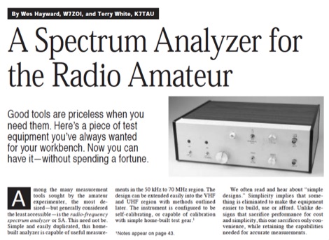 Demonstrates the construction of a **homebrew spectrum analyzer** designed by Wes Hayward, W7ZOI, and Terry White, K7TAU, enabling radio amateurs to build a capable test instrument without significant expense. The resource details a _double-conversion superheterodyne_ circuit, employing intermediate frequencies of 110 MHz and 10 MHz, and covers essential blocks such as the time base, logarithmic amplifier, resolution filters, and local oscillators. It highlights the use of hybrid and monolithic ICs, including mixers, amplifiers, and VCOs, to simplify construction while maintaining performance. The design supports useful measurements in the 50 kHz to 70 MHz range, with methods outlined for extending capabilities into VHF and UHF. The authors emphasize that this analyzer, while simple to build, is intended for serious measurements, requiring careful control of signal levels to avoid spurious responses. It uses an oscilloscope for display, with specific instructions for calibration and adjustment of various stages, including the log amplifier and IF gain. The guide provides detailed schematics and component lists for each section, such as the 110 MHz triple-tuned band-pass filter, which achieved **90 dB** image rejection, a significant improvement over double-tuned circuits. Practical advice on alignment and troubleshooting is included, drawing on the authors' extensive experience in RF circuit design.
 -
 Autotena, a Taiwanese manufacturer, offers a diverse product line focused on RF communication antennas and related accessories. The resource details various antenna types, including **4G/3G LTE wideband high-gain low-profile antennas**, land mobile wideband antennas, fiberglass omnidirectional designs, and GPS mobile and marine antennas. Specific amateur radio offerings include NMO VHF load coil gain antennas, VHF whip gain antennas with PL-259 connectors, and UHF NMO mount antennas with 3dB/5dB gain. The company also produces antennas for CB and 10-meter amateur bands, such as aluminum broadband 26-30MHz antennas and big copper coil broadband 26-30MHz antennas. Additionally, the site showcases **RF amplifiers** for CB, HF, VHF, and UHF bands, including professional-grade base station amplifiers with 100% EIA duty cycle. Handheld antennas, PL-259 type mobile antennas, magnet mount antennas, and external CB speakers are also presented, alongside various mounting kits and cable assemblies.
 -
 PstRotator handles just about every controllable rotator in common use: Prosistel, Green Heron, HyGain, RC1 MDS, Rotor-EZ Idiom Press, Yaesu Az and many more PstRotator includes automatic tracking for satellite or EME communications, using programs like WSJT, VQLog, TACLog, Z-Track, GJTracker, EME System, Trak_SM, WXtrack, WinOrbit, Orbitron, Nova for Windows, Sat_Explorer, SatPC32, Win-Test. PstRotator supports remote control over TCP/IP.
 -
 A 3.42-meter (11-foot 2-inch) extended-length mobile antenna project is presented, detailing its evolution from an initial 1.65-meter design. W5JGV shares his journey in optimizing mobile HF performance, noting that increasing the top whip length significantly improved radiation efficiency by reducing coil losses and allowing for larger wire gauges. The article includes a comparative table illustrating substantial gain increases, with the 3.42-meter version showing up to 40.6% efficiency on 21.2 MHz compared to a half-wave dipole. Construction details are thoroughly documented, from the use of hard-wall copper pipe for mast sections to the fabrication of custom loading coils. The author explains the necessity of an insulating brace for self-supporting coils and details a unique rotational alignment mechanism for off-center mounted coils to prevent snagging on overhead obstructions. He also describes a "Z" winding technique for 75-meter and 160-meter coils, which minimizes copper losses and manages dielectric losses. The resource provides specific loading coil data, including wire gauge, number of turns, coil length, and inductance values for bands from 18 MHz down to 2 MHz. It emphasizes that these coils may require fine-tuning based on individual vehicle and whip configurations, suggesting an antenna tuner for optimal mobile station operation across multiple HF bands.
 -
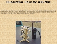 This is an antenna that author just built. Was intend for receiving the AO-27 downlink (at 436.800 +/- doppler). It is built with right hand circular polarization, and the gain is supposed to be in the neighborhood of 3 DB.