Search results
Query: antenna gain
Links: 271 | Categories: 6
-
 With over 20 years of experience, Proyecto 4 operates as a specialized ham radio retailer in Madrid, Spain, providing a diverse inventory of transceivers, antennas, and related accessories. The store features popular models like the _ICOM IC-705_ and _ICOM IC-7300MK2_, alongside Yaesu transceivers such as the _FTX-1 Optima_, which delivers 100W on HF and 50W on V/UHF bands. The product range includes mobile and portable antennas, such as the D-Original DX-NR770HB, offering 3 dB gain on 144 MHz and 5.5 dB on 430 MHz, and the Diamond RH-770 with a BNC connector. CB radio enthusiasts can find the Anytone CB SMART II AM/FM transceptor and the Telecom LS145 mobile antenna, rated for 500W and 4 dB gain on 26-30 MHz. Proyecto 4 emphasizes its in-house technical service, inviting customers to visit their laboratory for repairs and technical consultations via sergio@proyecto4.com. The store also highlights customer reviews and offers promotions like Yaesu Cashback, providing savings up to 100€.
 -
 Presents the design and performance of a 4-element wire Yagi antenna for the 40-meter band, building upon VE3VN's earlier 3-element switchable wire Yagi. The resource details the antenna's evolution, highlighting the transition from a 3-element to a 4-element configuration and the resulting improvements in gain and front-to-back ratio. It provides specific insights into the antenna's construction and expected operational characteristics. VE3VN shares insights from field results, noting the antenna's performance on 40 meters. The discussion includes the antenna's pattern and matching characteristics, crucial for any DXer or contester looking to optimize their signal on this popular HF band. The author's experience with the previous 3-element design informs the enhancements made to this 4-element iteration. The article includes a visual representation of the antenna's current view, offering a practical perspective on its physical layout. It serves as a valuable reference for hams considering a directional wire antenna for 7 MHz operations, demonstrating a practical approach to achieving enhanced directivity and gain.
 -
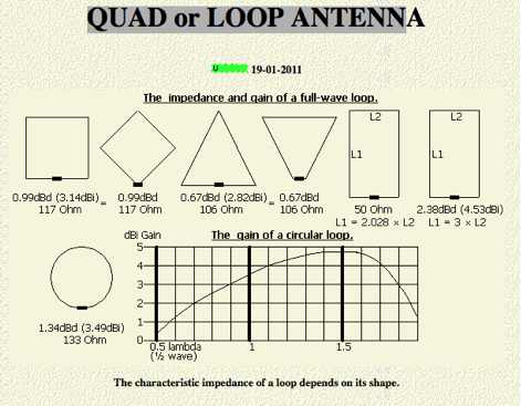 Quad and loop antennas comparisons, evaluating the impedance and gain of both antennas and considerationso n horizontal loop antennas for low bands by PA0FRI
 -
 The Vee Beam antenna project presents a versatile solution for hams, enabling operation across all eight High Frequency bands (80m to 10m) with significant gain on 20m to 10m. This easy-to-construct antenna utilizes two long wires at an angle, enhancing directional performance and minimizing ground losses. With a low visual profile, it is discreet and effective for various applications. The design allows for optimal leg lengths and included angles, ensuring robust performance while maintaining simplicity in construction and operation. The V Beam antenna is an aerial that you can use on all eight High Frequency amateur bands (80, 40, 30, 20, 17, 15, 12 and 10m) with an antenna tuner, and which gives significant gain on the five bands from 20 to 10 meters band.
 -
 A schematic antenna for a 40-80 Morgain dipole antenna with diagram and pictures, article partially in german
 -
 Demonstrates the design principles and performance characteristics of **corner reflector antennas**, emphasizing their high gain and directional properties. It covers critical design factors such as the corner angle and the spacing between the radiating dipole and the reflector vertex. The resource explains how reducing the corner angle increases gain but lowers feed impedance, making matching more challenging. Practical angles of 90 degrees or 60 degrees are discussed, with 90 degrees offering easier impedance matching despite slightly lower gain. Details key design considerations, including reflector side length exceeding two wavelengths and reflector width greater than one wavelength for a half-wave radiator. It specifies reflector construction using wire netting, sheet metal, or parallel metal spines spaced less than 0.1 wavelength. The article provides a table with general dimensions for UHF and VHF bands, noting typical impedance values of 50 to 75 ohms and expected SWR of 1.7:1 on the lower band edge. Adjustable radiator-to-vertex spacing is highlighted as crucial for final tuning.
 -

-
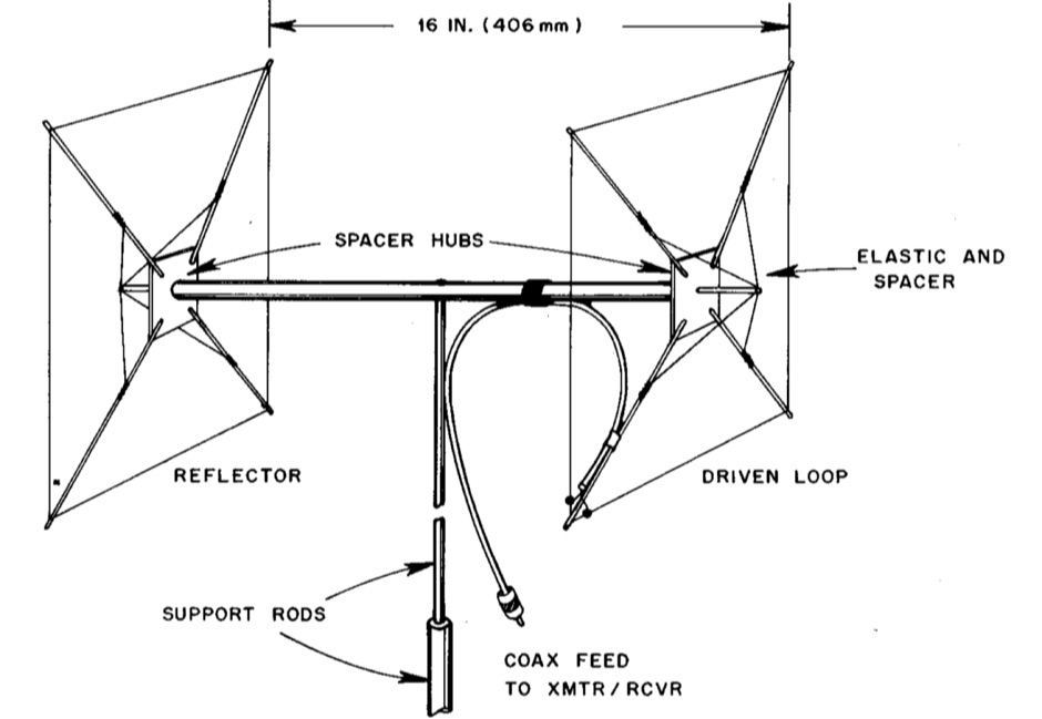 Backpacking, boating or mountaintopping ? Invest your time and pack this novel directional gain antenna on your next expedition
 -
 Notes on moxon antennas for VHF and HF bands. Main characteristics, gain and f/b ratio by DK7ZB
 -
 An introduction to history of Morgain Antenna, since the early origins in Virginia, to the current home made projects and design available on the net. Article in Italian
 -
 This document details the design and construction of a Vinecom 6N4 dual-band Yagi antenna for the 50MHz (6-meter) and 70MHz (4-meter) amateur radio bands. The antenna features 9 total elements (4 elements for 50MHz, 5 elements for 70MHz) on a 4.236-meter aluminum boom. Computer simulations using MMANA software predict 7.21 dBd gain on both bands with front-to-back ratios of 16.01dB (6m) and 15.37dB (4m). The design uses 12.7mm diameter elements mounted on a 32mm square boom, weighing 5.7kg total. Practical measurements with an MFJ-269 analyzer confirmed good SWR performance across both bands after element length adjustments.
 -
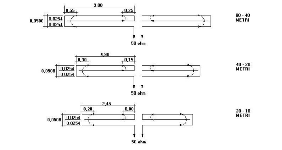
 The HB9CV is a well known two element antenna of a directional beam type with a forward gain of 4 to 5 dBd. This one is for two metres but it can be scaled, from the dimensions in the diagram, for other bands I have also made them for four and six metres
 -

-
 Understanding Gain differences, j-pole and end-feed vertical antennas.
 -
 A bowtie antenna is a type of antenna that reputedly provides higher gain at lower radiation angles than a center-fed dipole antenna at heights considerably less than 1/2 wavelength above ground.
 -
 A 50-ohm 10W resistor forms the core of this portable QRP antenna, designed by _K0EMT_ for convenient operation on 160m and 80m. The construction involves soldering the resistor to a BNC connector, with one lead to ground and the other to the center conductor, then insulating the assembly. This minimalist design aims to provide a highly portable solution for low-band QRP operations, acknowledging the inherent trade-offs between antenna size and efficiency. Testing with an antenna analyzer revealed low SWR on both 160m and 80m, with a Yaesu FT-817 confirming good matching. While 40m and 30m showed higher SWR, the primary focus remains on the lower bands. The author successfully tested the antenna with **2.5W CW** output, demonstrating its practical application for QRP field operations where ease of deployment is paramount, even if it means sacrificing some **gain** compared to full-sized antennas.
 -
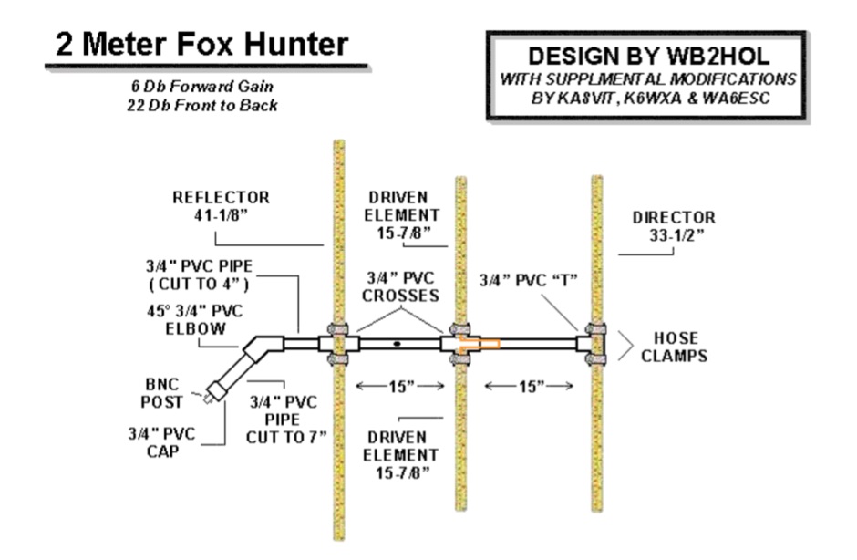 A home made yagi antenna featuring 6db forward gain and 22 Db front back
 -
 The Quadlong antenna for the six meter band. This antenna feature a total gain of 6,4 dBd, F/B 21 dB and is also available in 70MHz version. Includes detailed pictures and plot diagrams.
 -
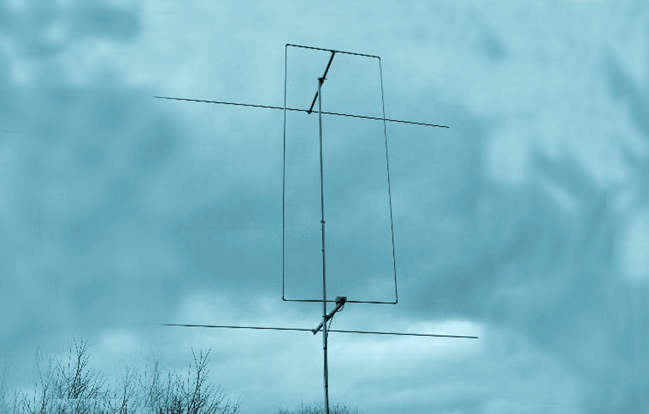
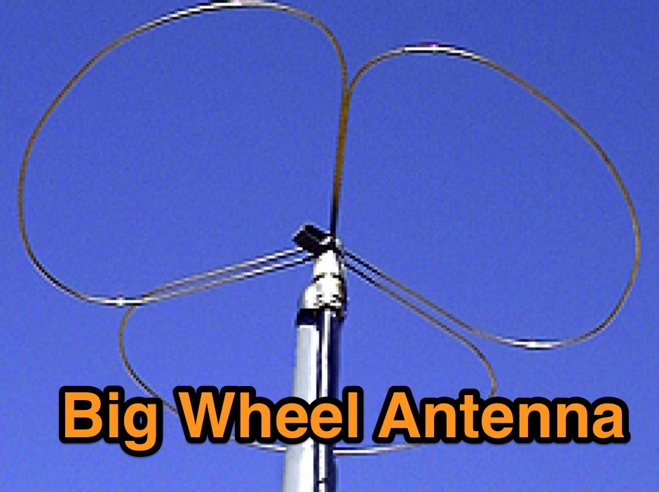 A Useful Horizontally Polarised Omni-directional Antenna with Gain for 144 MHz
 -
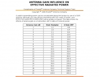 A radio's transmitting power can be concentrated along the horizon by use of a GAIN antenna. Although you may still be transmitting with four watts of power, your effective radiated powerwill be greatly increased. This table shows the effects of antenna gain on a transmitter with 4 watts of transmit power.
 -
 A Loop Fed Array Yagi antenna for 50 MHz featuring 11 dBi gain and 23 f/b ratio. In this excellent page the author even includes a detailed drawing in DWG format, with element lenght and spacing measures, in a separa file a full list of material list needed to build this yagi antenna including source and price, the EZnec file for this antenna plan, and a lot of pictures of this LFA Yagi for 50 Mhz. A ten page PDF file containing all infos, is also available to download.
 -
 A Unique VHF Antenna with gain over a J-Pole Jose I. Calderon, DU1ANV
 -

-

-
 The rhombic antenna is often claimed to be an exceptionally good antenna with very high gain. Modelling rhombic antennas
 -
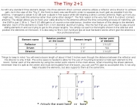 Similar to Tiny 2 but this three element direct connect antenna utilizes a reflector and a director to achieve gain.
 -
 The _Italian VHF Beacons_ resource provides a detailed listing of active and QRT amateur radio beacons operating across VHF, UHF, and SHF bands within Italy. Each entry specifies the beacon's callsign (e.g., IQ1SP/B), operating frequency (e.g., 144.411 MHz), QTH locator (e.g., JN44VC), effective radiated power (ERP) in watts, and antenna configuration (e.g., Big Wheel, 4x Dipole, Yagi). This data is crucial for radio amateurs involved in propagation studies, equipment testing, and long-distance (DX) communication on these higher frequency bands, offering fixed signal sources for monitoring. This compilation, last updated in October 2005, serves as a historical snapshot of Italian beacon activity. For instance, it lists several 144 MHz beacons with ERPs ranging from **0.1W** to **10W**, and higher frequency beacons such as I8EMG/B on 1296.880 MHz and I3EME/B on 24192.132 MHz. The inclusion of QRT (Quiet Radio Teletype) status for many entries indicates the dynamic nature of beacon operations over time. Users can utilize this information to identify potential signal sources for band openings or to calibrate their receiving equipment against known transmissions.
 -
 Operating on the 2200m band (135.7-137.8 kHz) often presents challenges for amateur radio transceivers, which typically exhibit poor receiver performance at these very low frequencies. This project addresses the issue by providing a design for a dedicated 137 kHz antenna preamplifier, specifically tailored to improve signal reception for radios such as the _Yaesu FT-817_. The preamplifier circuit utilizes a low-noise FET input stage, crucial for minimizing self-generated noise and maximizing the signal-to-noise ratio from weak LF signals. The design includes a detailed schematic, component values, and construction notes, enabling homebrewers to build a functional unit. The goal is to achieve significant gain, making the faint signals on 2200m more discernible and improving overall band usability. Key design considerations include impedance matching to typical antenna systems and ensuring stable operation across the narrow LF segment. The circuit aims for a **low noise figure** and sufficient amplification to overcome the inherent limitations of general-purpose HF transceivers when operating below **200 kHz**.
 -
 Operating an 80/40/20M fan dipole for DX is analyzed through EZNEC modeling, focusing on the antenna's performance in a real-world, low-height installation. The resource details the physical construction and SWR measurements of the fan dipole, comparing them against EZNEC simulations. It also incorporates High Frequency Terrain Analysis (HFTA) data to illustrate typical DX elevation angles for various regions from New England, providing a crucial context for evaluating antenna patterns. The analysis presents EZNEC-generated azimuth and elevation patterns for each band (80M, 40M, 20M) at specific frequencies, showing gain figures at different elevation angles relevant to DX propagation. It compares the modeled SWR with measured SWR, attributing discrepancies to coax attenuation. The study concludes with observations on the antenna's azimuth performance (omnidirectional within ±1.5 dB) and its less optimal elevation gain at desired DX angles, highlighting the impact of low antenna height on DX capabilities.
 -
 Carry a small stock of new and reconditioned parts for both rotators and control boxes for the following makes: CDE/HYGAIN , YAESU , STOLLE.
 -
 Two Delta-Loops in phase. The purpose of this article is to propose an antenna with a high gain, a high efficiency and a very low price that is easy to build for any frequency.
 -
 The grounded half loop describe in this article is basically a half wave length wire on 80 Meters. The 80M grounded half loop antenna, inspired by a 1984 QST article by SM0AQW, is a compact solution for limited spaces. Comprising a 127-foot wire fed against ground and supported by radials, it balances performance and practicality. Despite compromises in length and proximity to structures, the antenna delivers strong signal reports and effective multi-band tuning using an SGC 237 antenna coupler. Ideal for CW operation, it offers low SWR on 80-10M, though noise levels and safety considerations warrant attention. This versatile design excels in constrained environments.
 -
 Dish antenna and its theory and design for high performance applications such as satellite transmission and reception as well as microwave links. Parabolic Reflector Antenna: Dish Antenna The parabolic reflector antenna which is often called the dish antenna provides an antenna solution applicable for VHF and above where high gain and directivity are needed for all type of radio communications and radio reception.
 -
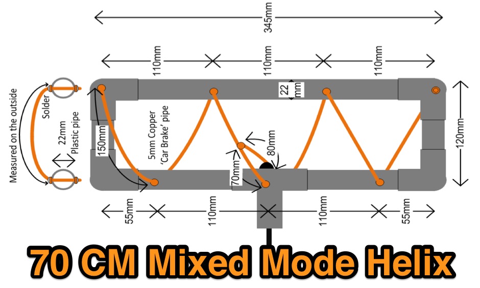 An experimental omni-directional antenna for 70cm which has both horizontal and vertical gain
 -
 A small sized and very cheap antenna project that allow you to work on WARC bands with a total gain very close to the dipole in both bands. On 12 meters is a normal dipole, while on 17 is a trapped dipole. Article in Italian
 -
 The GM4JJJ VHF and EME pages document David's extensive work in Earth-Moon-Earth (EME) communication, specifically on the 144 MHz band, and his involvement in amateur radio astronomy. The resource details his station setup and operational experiences, providing insights into the technical challenges and rewards of bouncing signals off the moon. It offers a glimpse into the specialized equipment and techniques required for successful EME contacts, a niche but highly rewarding aspect of amateur radio. David's content shares practical applications and field results from his EME endeavors, which can be particularly useful for hams contemplating or actively pursuing moonbounce operations. The information, while not a step-by-step guide, implicitly compares the complexities of EME with more conventional VHF/UHF operations, highlighting the significant power and antenna gain necessary to overcome path losses. This resource serves as a testament to the advanced capabilities achievable in amateur radio.
 -
 The electrical characteristics of an antenna that are of interest to obtain by direct measurement are the frequency at which the antenna is tuned, the gain and radiation pattern
 -
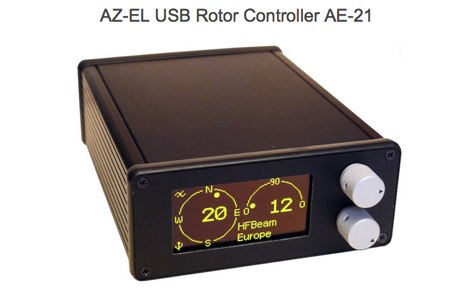 AF6SA USB antenna AZ-EL rotor controller compatible with Yaesu G-5500, G-450, G-650, HY-Gain and other AC motor rotors
 -
 Dimensions and EZNEC plots for a 2 Element 30 meter Yagi antenna with 28 Ohm featuring 4.3 dBd Gain and a 16dB F/B with a good bandwidth.
 -
 Protecting amateur radio equipment from transient overvoltages requires robust lightning and surge protection, which is the focus of Electronic Specialty Products. The company provides various devices, including coaxial lightning arrestors for antenna feedlines and surge protectors for AC power lines and data circuits. These devices are engineered to divert high-energy surges, such as those caused by direct or indirect lightning strikes, away from sensitive transceivers, amplifiers, and computer components, thereby preventing catastrophic damage. Key products include the _Coaxial Lightning Protector_ series, designed for various impedance levels and frequency ranges up to 3 GHz, and the _AC Line Surge Protector_ for shack power distribution. Effective deployment of these protection devices can significantly reduce the risk of equipment failure and ensure operational continuity during severe weather. For instance, a properly installed coaxial arrestor can handle peak currents of **20 kA**, while AC line protectors offer clamping voltages typically below 400V. Comparing different models reveals varying levels of insertion loss and return loss, with some coaxial units exhibiting less than 0.1 dB loss at 500 MHz, making them suitable for high-performance HF and VHF/UHF operations. Integrating these components into a comprehensive grounding system is crucial for achieving maximum protection against both common-mode and differential-mode surges.
 -
 Examining the _Angle of Radiation_ and its impact on amateur radio operations, the resource provides insights into optimizing antenna performance for DX and local contacts. It features a design for SPOTTO, a direct conversion high-performance universal DSB transceiver, detailing its construction and operational characteristics for homebrew enthusiasts. Additionally, the site presents a 7-element VHF high-gain antenna design, offering practical schematics and expected performance metrics for those seeking enhanced gain on VHF bands. The resource also covers the development and popularity of the _FT8_ digital mode, highlighting its effectiveness in weak-signal conditions and its role in special event operations like the FT8DMC anniversary. It includes information on Hamfest India 2023 and the Lamakaan Amateur Radio Convention, providing dates and organizational details for significant Indian amateur radio gatherings. Technical articles on Direct Digital Synthesizers (DDS) VFOs and low-cost multifunctional frequency counters offer practical project ideas for radio amateurs.
 -
 An high gain long yagi antenna, seven elements, for six meters band
 -
 The HF horizontal loop has been around for many years now. This article includes a YouTube video and discusses the reasons for looking at this antenna, its design, and its installation. There are some on-air comparisons against three regular double bazooka (coax) dipoles and the Par SWL End-Fed antenna.
 -
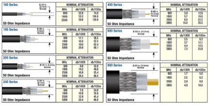 Types of coax-cable with rf attenuator calculator, line loss calculator form includes an antenna gain calculator. This coax loss calculator can help you on choosing the right cable for your antenna sysmte.
 -
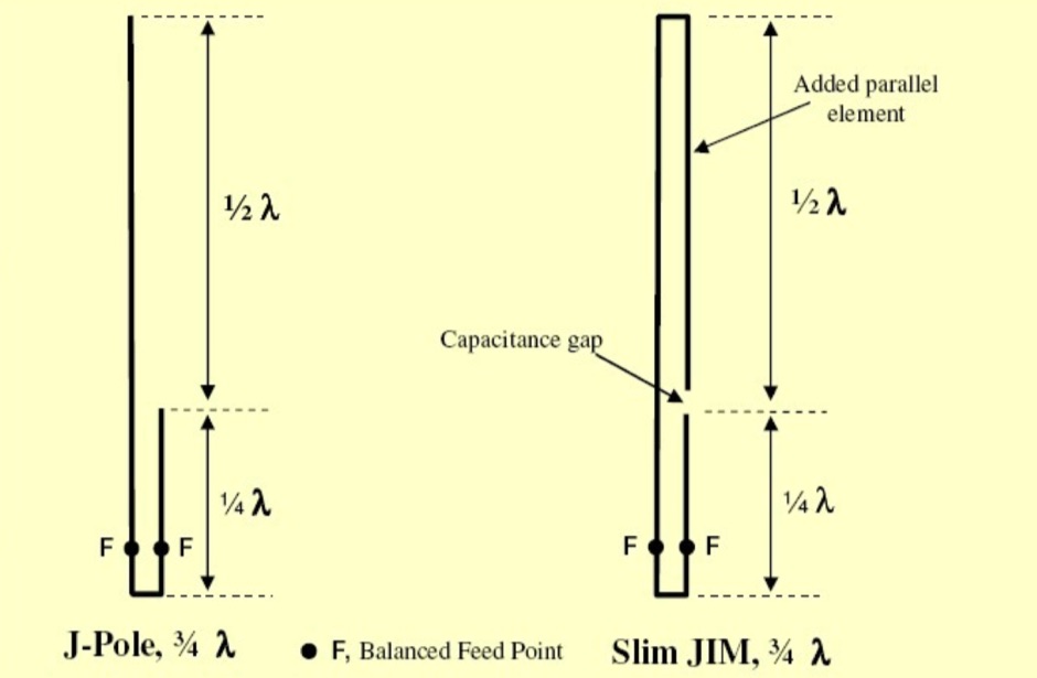 Build the Slim JIM Antenna, a unique VHF Antenna with gain over a J-Pole Jose I. Calderon, DU1ANV
 -
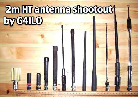 G4ILO compares popular antennas for 2 metre band handhelds so as to see how much you lose using a small inconspicuous antenna or how much you gain by using a long antenna.
 -
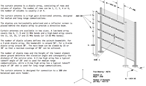 An antenna for shortwave radio broadcasting consisting of rows and columns of dipoles, is a high gain directional antenna, designed for medium and long range communications.
 -
 Operating magnetic loop antennas requires careful consideration of RF safety, particularly regarding near-field magnetic field intensity. This resource presents calculations for magnetic field strength (H-field) at various distances from a magnetic loop, emphasizing that the H-field is significantly higher than the E-field in the near-field region due to the inductive nature of the radiating element. It provides specific formulas and examples for determining safe operating distances based on power levels and loop dimensions, crucial for compliance with RF exposure limits. The analysis compares calculated H-field values against FCC and ICNIRP maximum permissible exposure (MPE) limits for controlled and uncontrolled environments. It demonstrates that even at QRP power levels (e.g., 5W), the H-field can exceed MPE limits within a few feet of the antenna, necessitating greater separation distances than often assumed for electric field considerations. The practical application of these calculations helps amateur radio operators configure their stations to ensure personnel safety and regulatory compliance when deploying compact, high-Q magnetic loop antennas.
 -
 A magnetic loop antenna for the VHF band, featuring a high gain that can be compared to a quarter wave vertical antenna
 -
 Hi-Z Antennas offers specialized high-impedance receiving systems, primarily focusing on phased vertical arrays for HF reception. Their product line includes preamplifiers designed for shortened vertical antennas, featuring optimized 15dB gain and array-matched characteristics. These components are engineered to enhance weak signal reception and improve signal-to-noise ratio across the HF spectrum. The company provides controllers for managing multiple vertical elements in a phased array configuration, enabling directional reception patterns. These systems are particularly effective for mitigating local noise and interference, a common challenge in urban and suburban operating environments. Specific offerings include solutions for 160-meter and 80-meter bands, addressing the unique requirements of low-band DXing. Technical details often reference components like the 2N3866 transistor in preamp designs and discuss concepts such as out-of-band attenuation. The focus remains on optimizing receiving antenna performance through impedance matching and active amplification, rather than transmit capabilities.