Search results
Query: field antenna
Links: 176 | Categories: 1
Categories
-
 High Speed Multimedia (HSMM) radio, as introduced by John Champa, K8OCL, represents a significant advancement in amateur radio's digital capabilities, moving beyond traditional keyboard modes like packet radio. This initiative, driven by ARRL's Technology Task Force, focuses on developing high-speed digital radio networks capable of up to 20 megabits per second. HSMM primarily facilitates digital voice (DV) and digital video (ADV), enabling real-time video transmission from emergency scenes to an EOC without expensive ATV gear, often requiring only a laptop, a PCMCIA card, a digital camera, and a small antenna. The working group's initial efforts concentrate on cultivating microwave skills within the amateur community to build and support portable and fixed high-speed radio-based local networking, or **RLANs**. These networks prove invaluable for RACES and ARES organizations, as well as homeland security and other emergency communications. Field Day exercises and simulated emergency tests (SETs) are encouraged to hone skills in rapid site surveys and deploying broadband HSMM microwave radio networks, with examples like linking Field Day logging stations or antenna test results at the Midwest VHF-UHF Society Picnic 2003. Getting started with HSMM often involves adapting off-the-shelf **IEEE 802.11** (WiFi) equipment to comply with amateur radio regulations, typically operating in the 2.4 GHz ISM bands. While consumer WiFi gear has range limitations under Part 15 rules, proper setup under amateur regulations can extend coverage significantly, with test networks like the Hinternet achieving 5-15 mile ranges at 54 M bit/s using small mast-mounted dish antennas. Careful selection of equipment with external antenna ports, high transmit power, and low receive sensitivity is crucial, along with using low-loss coaxial cable like LMR-400 for optimal performance at these frequencies.
 -
 DF0WD/DL4YHF's Longwave Overview details amateur radio operations on the 135.7 to 137.8 kHz segment in Germany. The author outlines the "inofficial" European band plan, specifying segments for QRSS, TX tests, beacons, conventional CW, and data modes. Early LF activities at DF0WD began with a 20-watt CW transmitter, later upgraded to a homemade linear transverter capable of 100 watts, driven by an Icom IC706 on 10.137 MHz. The station's antenna system includes a 200-meter wire, approximately 10 meters above ground, supported by football field light-masts. Despite its length, the antenna's efficiency is noted as very low due to the immense wavelength of about 2.2 km. The author's experience highlights the significant challenge of achieving effective radiated power (EIRP) on LF, estimating DF0WD's EIRP at around 80 milliwatts based on field strength measurements from PA0SE. DF0WD/DL4YHF has successfully worked numerous countries on 136 kHz CW, including DL, F, G, GI, GM, GU, GW, HB9, HB0, LX, OE, OH, OK, OM, ON, OZ, PA, and SM. The author also mentions ongoing efforts to log contacts with CT, EI, LA/LG, and to complete a two-way QSO with Italy, demonstrating persistent activity on this challenging band.
 -
 MARCA, Inc. operates approximately 24 repeaters across Arizona mountaintops and Phoenix-area rooftops, supporting modes like D-STAR and Fusion. The club, holding the **W7MOT** callsign, engages in diverse activities including ARRL Field Day events near Forest Lakes, AZ, ARRL FMT contests, and antenna experimentation. Members actively participate in HF operations such as voice, digital, CW, DXing, and various digital HF modes, alongside MESH and EOC operations within the valley. The club's interests span a broad technical spectrum, from SDR radio building to antique radio restoration, and include modern digital modes like WSPR, WSJT, FT8, and FT4. They also explore computer-based operations such as Echolink, fostering a dedicated Single Board Computer (SBC) and Raspberry Pi group. Monthly VE testing sessions for Technician, General, and Extra Class licenses are conducted by Ray Vasquez, K4RMV. Meetings are held on the third Tuesday of each month, typically lasting two hours, with a business segment followed by a technical presentation. These gatherings occur in-person at IHop in Mesa, AZ, and concurrently via Zoom, accommodating both local members and winter visitors. Informal chat groups often form post-meeting to discuss specialized topics like D-STAR, SDR, APRS, MESH, and Fusion.
 -
 This article presents a comprehensive guide to constructing a multiband vertical wire antenna. The design features parallel wires for various bands, all connected to a single balun, ensuring ease of assembly and adjustment. Materials required include a fishing rod, PVC tubing, and inexpensive wire. The antenna is lightweight, cost-effective, and suitable for field use or as an additional home setup. Detailed instructions and diagrams are provided to facilitate successful construction and optimal performance across multiple frequencies.
 -
 The magnetic loop, thus named by the use of the magnetic component of the electromagnetic field, is a parallel circuit LC. In this article a sample project to home made a custom antenna. The circular form is often met on the commercial models but this antenna can be hexagonal, octagonal or square.
 -
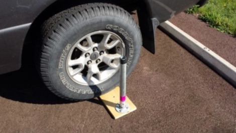 A homemade simple and inexpensive portable antenna support, handy for quick trips to the field and other portable operations
 -
 The club was founded in 1987 when a group of ham operators hauled radio gear, antennas, and a generator to the island by boat to operate portable during ARRL Field Day
 -
 Presents various amateur radio topics through blog posts, detailing operational experiences and technical insights from the perspective of SV2YC. The content frequently discusses antenna projects, such as a **portable 20m/40m dipole** designed for rapid deployment, and explores the performance characteristics of different wire configurations in varied field conditions. Observations on propagation and band activity across the HF spectrum are also regularly documented, providing practical context for fellow operators. Specific entries often include detailed accounts of **DX contacts** and participation in minor contests, outlining station setup, power levels, and antenna choices. The blog also covers modifications to commercial transceivers and homebrew accessory construction, offering practical advice on improving station efficiency and functionality. Further posts delve into software applications for logging and digital modes, sharing configurations and operational tips for maximizing their utility in daily amateur radio activities.
 -
 Constructing a dual-band antenna for 40 and 20 meters often involves compromises in size or complexity. This resource presents a compact _open sleeve dipole_ design that addresses these challenges by using 450-ohm ladder line and folded elements to achieve a total length of approximately **17.17 meters**, significantly shorter than a full-size 40-meter dipole. The design leverages electromagnetic coupling, where a primary radiator handles the 40-meter band, and a second conductor resonates on 20 meters without direct electrical connection. This configuration eliminates the need for traditional traps, loading coils, or switching components, simplifying construction and reducing potential loss points. The antenna is fed with RG-58C/U coaxial cable, and a common-mode choke is recommended at the feed point to suppress sheath currents, ensuring a cleaner radiation pattern and minimizing RF in the shack. The design is well-suited for portable operations, field deployments, temporary installations, and restricted urban environments where space is a premium, offering solid performance on both HF bands.
 -
 Have you ever thought of setting up a portable HF station for an activity like the Field Day ?
 -
 The Black River Amateur Radio Club (K8BRC) operates as a central hub for amateur radio enthusiasts within Van Buren County, Michigan, and its adjacent regions. This organization facilitates various activities, including local nets, educational initiatives, and community service events, all aimed at promoting the hobby and enhancing operational skills among its members. The club's focus on local engagement ensures a strong sense of camaraderie and mutual support among hams, from those just earning their _Technician_ license to seasoned DXers. Members frequently participate in field operations and emergency communications drills, applying practical skills in real-world scenarios. The club also maintains resources for new operators, offering guidance on station setup, antenna theory, and operating procedures. Their commitment to public service is evident through participation in events requiring reliable communication. K8BRC provides a platform for hams to share knowledge, collaborate on projects, and engage in on-air activities, strengthening the local amateur radio community. Many members have achieved **100** DXCC entities.
 -
 On the field comparison among C-Pole antenna, an EFHW vertical antenna and an Inverter V dipole antenna. Test is done using two identical WSPRLite beacons that transmit with 200mW on the WSPR frequency and analyzing spotted results.
 -
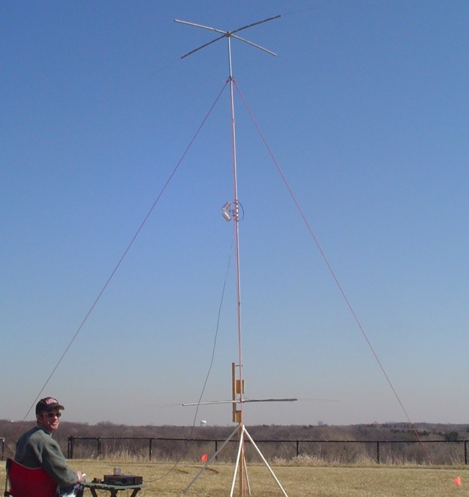
 This Field Day Vertical Antenna project is the result of many years of attending various field day sites and realizing that what was needed is a simple, easy to assemble vertical antenna. The design of this Field Day Antenna is not very novel and leverages ideas from Butternut verticals and ARRL publications. The one essential requirement was that the antenna can be raised by just one person. The design of this Field Day Antenna is an above ground mounted ground plane vertical.
 -
 Dipole antennas, vertical half-wave dipole antennas with impedence tranformes that can be used for portable operations. Some well worn antenna configurations are the easiest and loudest lash-ups you can try.
 -
 The PAC-12 Antenna, a multi-band portable vertical, is meticulously detailed in this construction article by James Bennett, _KA5DVS_. The design emphasizes ease of homebrewing using readily available components from local hardware stores, including replaceable loading coils. It outlines the preparation of the 72-inch telescoping whip (originally from Radio Shack, with an alternate source now provided by _Pacific Antenna_), the construction of the loading coils from PVC risers, and the fabrication of the aluminum rod base sections. Specific instructions cover threading aluminum rod with a _1/4-20 threading die_ and assembling the feedpoint insulator with a BNC connector, along with recommendations for radial deployment. KA5DVS, an avid traveler and QRP enthusiast, developed the PAC-12 to address the bulkiness of random wire setups and the limitations of commercial portable antennas like the Outbacker or SuperAntennas MP1. His goal was a lightweight, packable antenna that disassembles into 12-inch sections, achieving an assembled length of approximately 8 feet. The design strategically places the loading coil away from the base for improved efficiency. The PAC-12 notably placed first in efficiency compared to a quarter-wavelength wire vertical at the HFPack antenna shootout during the Pacificon conference in October 2001, demonstrating its practical performance for field operations. Appendix C showcases various _NJQRP Club_ members' PAC-12 constructions, including a 20m beam made with multiple PAC-12 elements.
 -
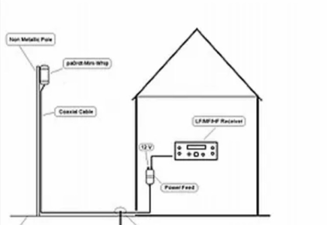
 A small active voltage probe antenna to aid reception on the LF bands
 -
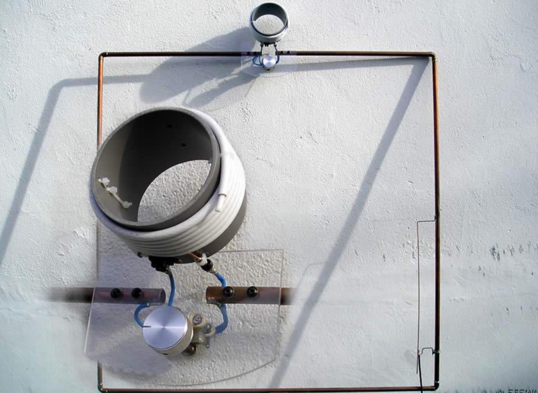
 The video showcases the setup of a 300 MHz oscillator, a 100W radiofrequency amplifier, and a dipole antenna for transmitting radio waves, leading to the fluorescence of a nearby light bulb. It demonstrates the presence of standing waves on the dipole antenna and how intensity varies along its length. Additionally, the usage of a copper pipe as a receiving antenna is explored, showing changes in intensity depending on alignment and proximity to the transmitter. Finally, a B field antenna sensitive to magnetic fields is introduced, revealing brightness variations in different orientations. The video offers insightful observations on radio wave transmission and reception phenomena.
 -
 The _G3TSO_ Mobile Antenna Page details construction and tuning methods for mobile antennas operating across **10 to 160 metres**. The content describes a Hustler-based design, optimized for RF performance and vehicle speeds, featuring centre loading. For optimal operation on various bands, the loading coil placement requires clearance from the vehicle body. Antenna resonance is critical for efficient mobile operation. A mobile antenna's base impedance may be as low as 27 ohms, requiring specific matching to achieve maximum radiation, as a minimum SWR at the transmitter does not always indicate resonance or maximum output. Tuning involves physical adjustment of antenna length to achieve resonance at the operating frequency. The _G3TSO_ page outlines a tuning procedure utilizing a low-power signal source and a field strength meter to identify maximum radiation before impedance matching. Loading coil placement, either at the base, center, or top of the antenna, influences radiation efficiency and mechanical stability for mobile installations. Centre-loaded whips, such as the Hustler design, offer a compromise between efficiency and stability, often for single-band operation. Helically wound antennas, including those for **28 MHz**, may present base impedances around 17 ohms, resulting in a 3:1 SWR at resonance. Low resistance grounding at the antenna base is also specified for optimizing performance and minimizing RFI during mobile operation. DXZone Focus: Mobile | Any | Antenna Tuning | HF
 -
 In the quest for an ideal field portable antenna, the author recounts experiments involving various wire configurations. While a previous candidate, a 41ft random wire, proved effective but lacked stealth, the search led to a surprising rediscovery of a design previously rejected—the Rybakov Antenna. With a focus on simplicity, rapid deployment, and multiband capability, the author explores the versatility of a 26ft Rybakov, avoiding the halfwave trap. The article delves into the antenna's performance and its potential as a discreet, resonant solution for field operations, addressing the challenges encountered during a POTA activation. Additionally, the Unun/Balun design used in conjunction with the Rybakov Antenna is discussed, providing insights into achieving a balanced system.
 -
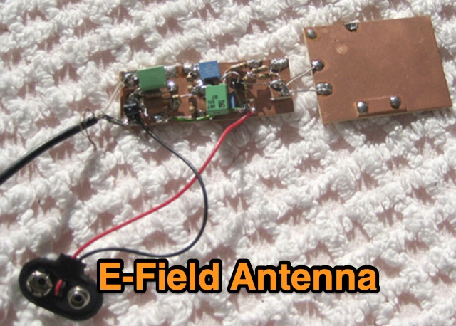
 The author investigated electric field antennas and achieved promising results with a shortened active whip antenna (30 cm). The findings suggest that at LF, active whips function primarily through electric field capacitance coupling.
 -
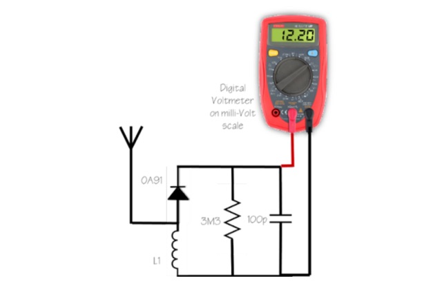 Mad your own simple FS meter. It is the simplest thing to make and is good enough to see if the antenna under test is radiating more power than your old ground plane, old mobile vertical or just radiating at all in a particular direction or in all directions.
 -
 This practical, hands-on article offers a valuable journey through balun construction for portable antenna systems. The author skillfully navigates from theoretical debates to practical implementation, providing a well-documented DIY process using RG316 micro coax and an FT114-43 toroid core. The step-by-step instructions, complemented by photographs, make this complex technical project accessible to hobbyists. Particularly impressive is the author's focus on lightweight design (just 173 grams) for SOTA field operations. While the final antenna requires minor tuning adjustments, the successful field test during the Pirate Contest demonstrates the effectiveness of this approach. An excellent resource that transforms theory into practical application for ham radio operators.
 -
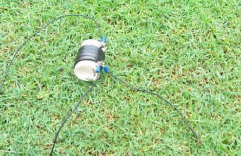
 How to Design and Build a Field Expedient End-Fed Half-Wave Antenna for 20m, 40m and 80m. This Shorty 80m EFHW comprises a 49:1 autotransformer (to match the very high impedance at the end of a half-wave wire), a half-wavelength wire for 40m (also a quarter-wavelength for 80m), a loading coil and a short tail wire. The coil and the short tail wire (about 6 feet) make up the other quarter wave on 80m.
 -
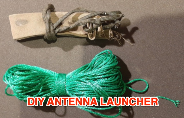 This article explores budget-friendly methods for launching wire antennas into trees, comparing common options like slingshots and professional arborist tools. The author introduces a simple and cost-effective DIY approach using latex balloons, sand, and readily available materials for efficient antenna deployment in the field
 -
 The author explores a portable version of the half-square antenna, typically a single-band structure. Using a 9:1 unun for versatility, they describe construction with speaker wire, deployment using collapsible poles, and field tests, achieving successful contacts on multiple bands. The article suggests efficient matching methods and concludes with the antenna's integration into the author's portable options.
 -
 Steve Nichols, G0KYA, presents a practical examination of ground systems for vertical antennas, drawing heavily on the empirical research of Rudy Severns, N6LF. He explains that a robust radial field is crucial for ground-dependent verticals, effectively replacing the antenna's "missing half" and mitigating severe RF absorption in lossy soil. Nichols clarifies that surface radials do not strictly require a quarter-wavelength; instead, deploying a minimum of 16 to 32 shorter wires often yields superior results compared to fewer, longer ones. The presentation also addresses the common SWR paradox: a poor ground might show a perfect 1:1 match, but adding radials, while potentially raising the SWR to around 1.4:1, significantly improves true radiation efficiency. Nichols defines counterpoises as elevated wire networks that substitute for earth connections, offering solutions for limited-space installations, such as the **Folded Counterpoise (FCP)** for 160 meters. This resource provides actionable engineering data for optimizing vertical antenna performance.
 -
 WB8LZR details the construction and initial field results of a multi-band vertical wire antenna, designed to complement his existing horizontal loop for improved DX on 80 meters. The antenna utilizes a 67-foot vertical wire, configured as a quarter-wave radiator on 80m, and employs a 1:1 current balun for RF isolation on 80m, 30m, and 17m. For bands like 40m, 20m, and 10m, where the wire acts as a half-wave or full-wave radiator, an additional impedance transforming _unun_ is integrated to manage the significantly higher feedpoint impedance and voltage. The author notes the vertical's performance as a receiving antenna, observing reduced noise compared to his main horizontal loop, particularly on 80m, and even hearing some long-path signals the loop missed. Initial QRP contacts, including a **1-watt** QSO with a _VP2 station_ on 30m, demonstrate its transmit capability. While the radial system is currently rudimentary, the project outlines practical considerations for multi-band vertical deployment and impedance matching.
 -
 The mini Radio Solutions miniVNA PRO is the only affordable vector network analyser (VNA) I know of that offers remote wireless operation. This is very interesting because it allows to measure the input impedance of HF antennas installed at height without having to deal with coax cable lengths, baluns nor common mode suppression chokes. However, to render the miniVNA PRO truly field proof, it requires a number of significant modifications.
 -
 Personal web site by N9SKN about portable QRP operations with pictures of several portable setups and antenna solutions.
 -
 In this article the author describes his personal experience on some antennas for 50 MHz he tested on the field, the six meter Dipole, Vertical, Moxon, a 3 element Yagi and an Omniangle antenna.
 -
 Constructing a 5-element quad antenna, the author aimed for low cost and simplicity, resulting in an effective design with 11 dBi gain and SWR of 2:1 or better across the 2-meter band. Using wood and dowels, the antenna costs under $8 and takes less than two hours to build with basic tools. The model predicts excellent performance, confirmed by ARRL Lab measurements. Practical field results demonstrate improved communication, even in simplex mode.
 -
 A rotatable 40-meter dipole antenna designed and constructed to fit within backyard constraints. The project utilized two fishing poles attached to a fiberglass center pole, resulting in an easy-to-build, lightweight, and cost-effective antenna. Essential materials included fishing rods, a center support pole, mast support, and basic tools. Linear loading was implemented to achieve the necessary length for optimal performance. The antenna, which proved effective during the contest, is ideal for field days and additional contest bands. Assembly and installation were straightforward, showcasing the antenna's practicality and efficiency.
 -
 Four distinct amateur radio bands, specifically 40, 30, 20, and 15 meters, are addressed by a portable dipole antenna design. This antenna utilizes a manual switching mechanism, employing "fast-on" or flying connectors to change bands. The design is presented with an animated plan, illustrating how operators can adjust the operating frequency by opening and closing specific connections on the antenna elements. The resource describes a _4 savos dipol_ (4-band dipole) that can be shortened for specific band operation. It provides practical information for hams seeking to construct a versatile, multi-band wire antenna for portable operations or fixed station use. This design offers a straightforward approach to achieving multi-band HF capability without complex tuning units, making it suitable for field deployments like SOTA or POTA activations where rapid band changes are beneficial.
 -
 Constructing an effective antenna support system often involves safely elevating wire antennas into trees or over obstacles. This resource details the build process for the WT8WV "Colossus" air cannon antenna launcher, a pneumatic device designed to project a pilot line over elevated structures. It specifies the use of readily available PVC pipe components and standard hardware, outlining the exact materials required and providing step-by-step assembly instructions for a robust, low-cost solution. The article presents a practical alternative to traditional methods like slingshots, emphasizing the launcher's utility for Field Day operations and general antenna deployment. It includes a comprehensive list of parts, such as 2-inch and 1-inch PVC pipe, various fittings, a sprinkler valve, and a bicycle pump valve, detailing their integration into the final assembly. The total cost for materials is estimated at around $40 per unit, making it an accessible project for many radio amateurs. Crucially, the guide incorporates essential safety precautions for operating a pneumatic launcher, covering aspects like pressure management and projectile selection. It also features multiple photographs illustrating the construction phases and the completed device, offering visual clarity to aid builders in replicating the design.
 -
 A vertical antenna project for POTA operations. This shortened antenna is aimed to work from 20 to 40 meter band implementing a loading coil, with an additional wire lenght, determined by on field testing and tuning.
 -
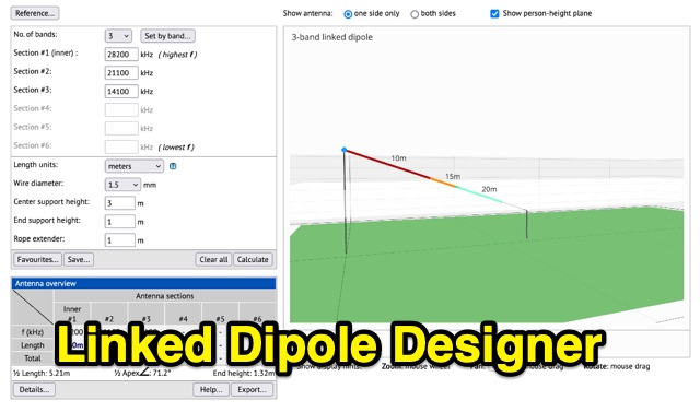 The page for designing linked dipole antennas allows users to swiftly create a versatile multi-band antenna suitable for portable applications in outdoor settings, such as in the field or on mountain tops.
 -
 For amateur radio operators engaging in portable operations like SOTA or POTA, rapid deployment of an effective antenna system is paramount. This video resource details the assembly process for the Buddipole multiband dipole antenna, showcasing its components and how they fit together. Rob, VK5SW, systematically presents the mast, coil arms, radiating elements, and the VersaTee hub, emphasizing the modular design that allows for quick configuration changes across various HF bands. The demonstration highlights the antenna's adaptability for different operating environments, from a ground-mounted vertical to a horizontal dipole. The video illustrates the ease with which the antenna can be packed and deployed, making it a practical choice for activations where setup time is limited. The Buddipole's design facilitates efficient band changes and tuning, crucial for maximizing QSO opportunities during field operations.
 -
 The Smith Chart, named after its inventor Phillip H. Smith, is a graphic tool used to solve transmission line problems in the field of ham radio operations. By using the Smith Chart, ham radio operators can determine the feed point impedance of an antenna, design impedance-matching networks, and optimize power transfer between a source and its load. The chart consists of resistance and reactance circles, providing a visual representation of complex mathematical relationships related to transmission line operations. Understanding and utilizing the Smith Chart is essential for hams looking to enhance the performance of their RF circuitry.
 -
 This page allows hams to design a vertical-plane delta-loop antenna for a single amateur HF band in different configurations. By choosing different feed-point positions, operators can observe variations in polarization properties, radiation patterns, and feed-point impedances. Users can generate radiation pattern plots, VSWR charts, antenna current diagrams, and Smith charts for their antennas over various ground types. Through adjusting the antenna's physical dimensions and refreshing the plots, hams can gain insights into the antenna's performance in the field. The page also discusses how elevation radiation patterns may change based on the antenna configuration and feed-point position.
 -
 This page provides information on designing a lightweight Moxon antenna for the upper HF bands and VHF. The Moxon antenna is a compact version of a 2-element Yagi with folded elements, offering good forward gain and a high front-to-back ratio. It is designed for a single band with a feed-point impedance close to 50 ohms. Hams can orient the antenna horizontally or vertically, with polarization following the configuration, affecting radiation patterns. The page allows users to generate radiation pattern plots, VSWR charts, antenna currents diagrams, and Smith charts for their antennas on different ground types, helping them understand antenna performance in the field.
 -
 The article offers practical guidance for setting up Field Day antennas, emphasizing the unpredictability and need for quick adaptations. It provides a comprehensive table of wire lengths for various bands and antenna types, using 1mm bare wire, in both metric and Imperial units. The author highlights the benefits of this table in saving time and reducing errors. While acknowledging potential variations due to construction and environmental factors, the article presents the table as a reliable starting point, with plans for future updates to include more bands and antenna types. This resource is valuable for ensuring efficient and accurate antenna setup during Field Day events.
 -
 The Portable EFHW antenna for the 40, 20, 15, and 10-meter bands utilizes a broadband transformer with a 1:49 ratio, designed on a PCB by either Jan or DL2MAN. The design incorporates an **FT114 core**, offering an alternative to the FT82 core. The antenna requires precisely 20.5 meters of DX Wire Ultralight for optimal performance. Additional components include DX Wires "Dyneema" 1mm rope and 1mm bricklayers string for structural support. The SWR plot indicates performance at two elevation heights: 5.5 meters (blue line) and 4 meters (yellow line), demonstrating optimization for low-elevation portable use without poles. The antenna's components, including spool and rope tensioners, are available for 3D printing, with spool dimensions scaled to 130% for a length of approximately 110mm. The design emphasizes simplicity and portability, suitable for field deployment.
 -
 The article describes a high-gain, compact beam antenna design for the 2-meter band (144-146 MHz). The NSH 4x4 Boomer is a 4-element antenna that is mounted on a 4-foot boom with an 8.2 dB gain, 1.2:1 SWR, and a front-to-back ratio of 18 db. It is designed for mobile operations and little area, making it perfect for field usage such as disaster management. The design employs regularly spaced parts with a straightforward gamma match for tuning, and the construction materials include a square boom and polished aluminum tubes. In local and portable tests, the antenna worked regularly, achieving contact distances of up to 15 kilometers.
 -
 Andrew Georgakopoulos, SV1DKD, modeled the End-Fed Half Wave (EFHW) antenna using MMANA-GAL software. He evaluated the EFHW-8010-2K from Myantennas.com for field operations, comparing it to random wires, OCFD, and dipole antennas. His results showed similar performance to OCFD, confirming EFHW's practical feeding advantage but with potential high-voltage risks at the feed point
 -
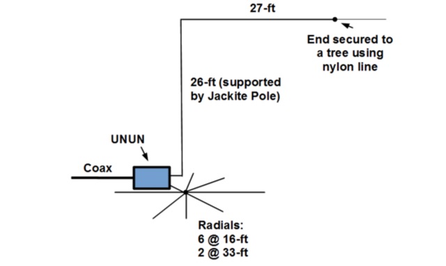 Inverted L antenna, even if not completely freestanding, it only requires one line to be lauched into a tree to support the end of the horizontal wire. This project is done with a 31-foot Jackite pole for a support and uses six 15-foot radials and one 33-foot radial.
 -
 This blog post documents the author's journey building an APRS micromodem for amateur radio applications. Using an open-source design by LY2EN, the author assembled a cost-effective Terminal Node Controller (TNC) with SMD components, an Arduino Nano, and a JDY-31 Bluetooth module. The construction process included PCB fabrication, careful component soldering, microcontroller programming, and Bluetooth configuration. A custom 3D-printed case protected the completed device. Field testing in Romania showed the device functioned with a Baofeng UV-5R radio, though antenna limitations affected performance. The entire project demonstrates an affordable DIY alternative to commercial APRS trackers.
 -
 This page provides guidance on designing an End-Fed Half-Wave (EFHW) or Random-Length antenna for amateur HF bands, such as 80 or 40 meters. The content explains how to optimize the antenna for multi-band use and match it to a 50-ohm system using an unun. Hams can generate radiation patterns, VSWR charts, and antenna current diagrams for their customized antenna designs. Understanding how antenna dimensions affect performance is essential for successful field operations. The page caters to ham radio operators looking to build efficient and effective HF antennas for their stations.
 -
 PH0NO conducted field tests comparing a mobile antenna (DX-UHV) to an end-fed half-wave wire. Results on 20m showed the end-fed wire outperforming the mobile antenna, with a significant difference in signal strength. On 40m, the end-fed wire surpassed the mobile antenna in spots and reach. While the mobile antenna is more practical, the end-fed wire offers superior performance. Further testing is planned.
 -
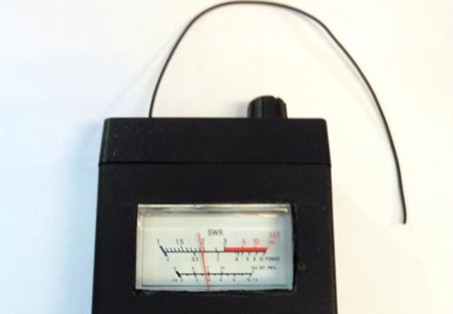 The field strength meter (FSM) is a very useful addition to any HAM toolbox. If you are messing around with antennas, or building PA's, or trying to repair some TX gear, the FSM will come to your rescue when there is doubt about the output level.
 -
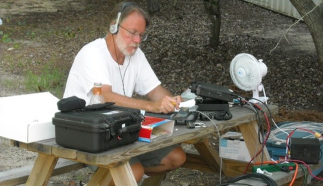 This article is from the book Ham Radio For Dummies and features some tips for portable amateur radio operations, on Field Day or generic outdoor operation, like selecting the proper antenna and portable power.