Search results
Query: input
Links: 193 | Categories: 0
-
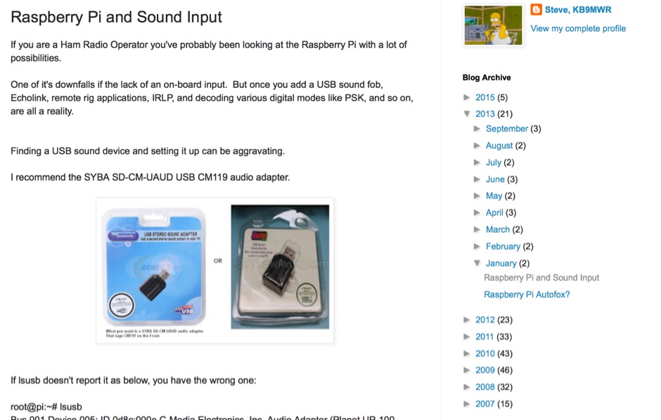 Connecting and configurig an USB Sound Card key to the raspberry Pi to allow digital mode decoding and remote rig applications
 -
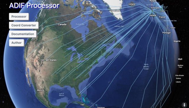 The ADIF Processor is an online application that visualizes amateur radio contacts from an ADIF log file using Google Earth. SOTA CSV log files can also be used. As well as allowing you to view and explore your contacts in Google Earth, you will be able to see a Markdown or text table of contacts, use the output ADIF file which contains QRZ.com data, accurate contact distances and fields populated from comments in the input file. Print QSL labels. One of the benefits of using the ADIF Processor before uploading/storing your ADIF file is detecting errors in callsigns and activity references (e.g. POTA or SOTA references).
 -
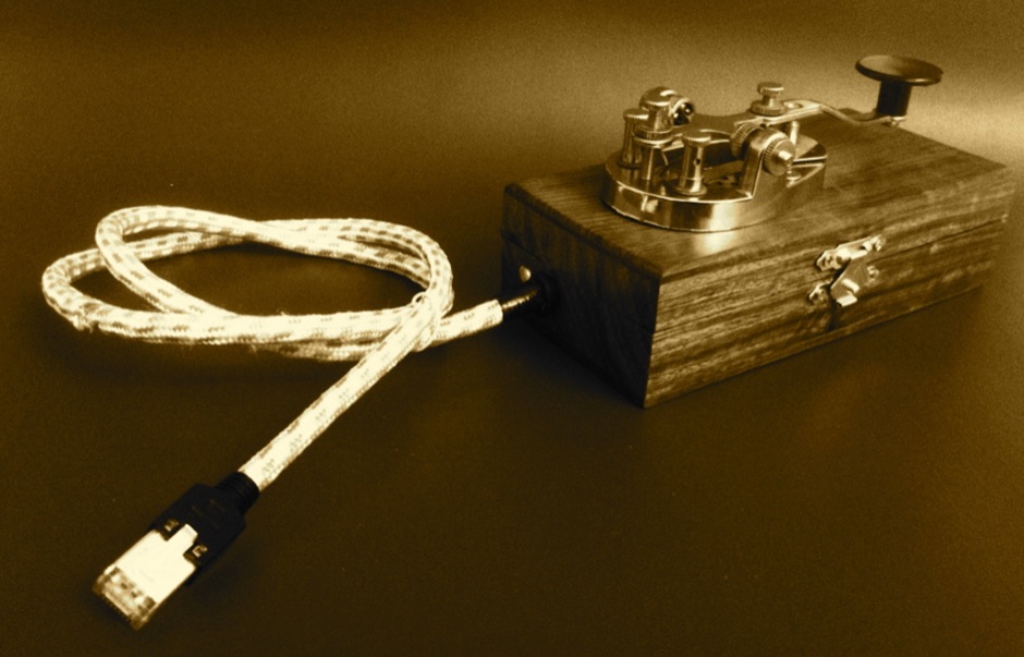 An open design exercise in interface archaeology, that decodes the input from a classic Morse key to send twitter messages
 -
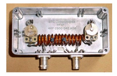 This unit uses four capacitors, only two of which are variables, and a single tapped coil. It is built in a die-cast box, and has been tested up to 80W input power on 70MHz by G4CJZ
 -
 There is a common perception that placing a balun on the input of a tuner causes the balun to work better. The thought is the balun operates with a matched impedance and that reduces balun losses. It also is thought that moving the balun improves balance.
 -
 1.5 dB of matched line loss can be calculated for a given transmission line using this online tool, which employs a model calibrated from empirical data. The calculator allows radio amateurs to input specific transmission line types, such as _RG-8_ or _RG-58_, and then determine the expected signal attenuation. This is crucial for optimizing antenna system efficiency and understanding power delivery to the radiating element, especially for HF and VHF operations where feedline losses can significantly impact performance. Beyond matched loss, the calculator also provides an estimate for mismatched loss if the Standing Wave Ratio (SWR) is specified. This feature helps operators quantify the additional power loss due to impedance discontinuities between the transceiver, feedline, and antenna, which is a common concern in amateur radio installations. Accurate loss calculations are vital for effective station design and for predicting actual radiated power. The tool's utility extends to various operating scenarios, from fixed station setups to portable deployments, aiding in the selection of appropriate feedline lengths and types to minimize signal degradation. Understanding these losses is a fundamental aspect of maximizing the effectiveness of any amateur radio antenna system.
 -
 Inches and meters Javascript Wavelength Calculator allow to input a frequency in MHz and calculate wavelenght in several units considering also fractions of wavelenght and the velocity factor. Includes an usefull inch to meter converter
 -
 TACLog offers a distinct approach to contest logging for **VHF/UHF/SHF** operations, diverging from the rigid input formats often found in other logging applications. This software prioritizes operational freedom, allowing contesters to input data in a sequence that suits their workflow during a fast-paced event, rather than being constrained by predefined field orders. It's particularly tailored for those participating in contests governed by **Region 1 rules**, ensuring compliance with established regulations. The program's design focuses on practicality for serious contesters, providing a robust platform for managing contacts. Its support for the EDI format is a significant advantage, streamlining the process of submitting logs to contest committees and facilitating data exchange within the amateur radio community. My experience with various logging tools confirms that flexibility in data entry can dramatically improve efficiency during multi-operator or high-rate single-operator contests, where every second counts.
 -
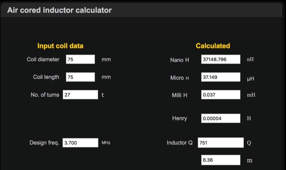 Online calculator for Input coil data, LC Resonant Frequency and L match
 -
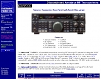
 The Kenwood TS-870S HF transceiver features two state-of-the-art 24-bit 20 MIPS DSP chips, providing over 100dB out-of-passband attenuation and CW bandwidth adjustable to 50 Hz. It operates across 160-10 meters with 100 watts output, incorporating digital filtering, a beat canceller, and 100 memory channels. The radio also includes a transmit equalizer, RX antenna input, and a K1 Logic Keyer, enhancing signal processing and operational flexibility for amateur radio operators. Advanced capabilities include IF stage DSP, dual noise reduction, and an auto notch filter, all contributing to superior signal reception and clarity. The TS-870S offers a variable AGC, voice equalizer, and an RS-232C port for computer control, with Windows™ software supplied. Its built-in automatic antenna tuner functions on all bands for both transmit and receive modes, streamlining station setup and operation. Available accessories such as the DRU-3A digital recording unit, SO-2 high stability crystal oscillator, and VS-2 voice synthesizer option further extend the transceiver's utility. The unit requires 13.8 VDC at 20.5 Amps and is supplied with an MC-43S hand microphone, making it a comprehensive station component.
 -
 Demonstrates the fundamental principles for connecting a personal computer to a ham radio transceiver, specifically for utilizing sound card-based digital mode software like those in the MM Hamsoft suite. It details the basic hardware setup, emphasizing the use of shielded leads and proper audio routing from the radio's output to the sound card's input, and from the sound card's output to the radio's microphone or data input. The resource highlights the critical need for transmit attenuation, suggesting a 100:1 voltage divider to prevent overdriving the transmitter's audio stage, and mentions the optional addition of ferrite beads and decoupling capacitors for RFI mitigation. The guide also points to external resources for more detailed pin-outs and interface schematics, such as a specific QSL.net page, and recommends consulting the help files within MM Hamsoft programs for interfacing specifics. It underscores that while the process is straightforward, understanding the audio level management and proper cabling is key to successful operation. The author, VE5KC, provides practical advice drawn from common issues encountered by operators setting up digital mode stations.
 -
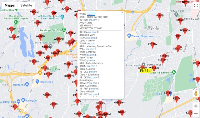 The resource provides an interactive map interface for locating amateur radio license holders across the United States. Users can input a _callsign_, _gridsquare_, zip code, or street address to center the map, which then dynamically populates with station markers. This functionality allows for precise geographical searches, revealing the distribution of hams within specific areas. Upon initial search, the map renders with adjustable zoom and pan capabilities. A key feature is its automatic reload mechanism: after two seconds of inactivity, the map updates to display stations within the newly viewed area. This ensures that the displayed data remains relevant to the user's current focus, whether exploring a densely populated urban center or a more remote region. Further interactive elements include clickable gridsquare labels, which re-center the map, and a "Show gridsquares" checkbox for toggling grid line visibility. Clicking on individual station markers reveals a popup containing the licensee's name and address information, making it a practical tool for geographical station identification.
 -
 This antenna is a vertical loop antenna mounted on a 8 meters high grounded mast with an input impedance of 50 Ohms without a matching device
 -
 The Kenwood TS-450S is a formidable transceiver covering 160 through 10 meters including the WARC bands with 100 watts input
 -
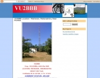 The VU2BBB repeater, located in Matheran, Maharashtra, commenced operations in the late 1980s, a significant undertaking by the Bombay Repeater Society. This repeater facilitates VHF and UHF communications for local amateur radio operators, providing extended range and improved signal reliability across challenging terrain. Its establishment marked a key development in regional amateur radio infrastructure, offering a crucial node for local nets and general QSO traffic. The repeater's operational parameters include specific input and output frequencies within the 2-meter band, typically utilizing a standard offset. CTCSS tones are often employed to mitigate interference and ensure selective access for authorized users, a common practice for repeaters in densely populated areas. Regular maintenance and upgrades ensure _VU2BBB_ remains a reliable asset for the amateur community, supporting emergency communications and daily amateur radio activities. The _Bombay Repeater Society_ continues to oversee its operation, reflecting a sustained commitment to local ham radio services.
 -
 Constructing a high-performance RF spectrum analyzer up to 1000 MHz requires careful attention to component selection, shielding, and circuit isolation. This resource details a project that improves upon the _Spectrum Analyzer for the Radio Amateur_ design by Wes Hayward (W7ZOI) and Terry White (K7TAU), incorporating ideas from Scotty Sprowls' project, particularly his 1013.3 MHz IF bandpass cavity filter. The analyzer utilizes a Mini-Circuits SRA-11 mixer with a sweeping local oscillator from 1013 to 2013 MHz, feeding into a 4-pole copper pipe cavity filter. The design employs a second SRA-11 mixer with a fixed 1024 MHz LO to produce a 10.7 MHz final IF. This signal then passes through narrowband resolution filters and is processed by Analog Devices AD603 and AD8307 ICs for IF amplification and logarithmic detection, driving an oscilloscope in X/Y mode. The project emphasizes modular construction, using salvaged components and double-sided FR4 material for PCBs, with critical notes on minimizing spurious images through effective shielding and proper voltage regulation for each module. Key components include a Z-Communications V585ME48 VCO for the first LO and a Z-Comm V583ME01 VCO controlled by a Motorola MC145151 PLL for the second LO. An optional Hittite HMC307 step attenuator and K&L 5L121-1000/T5000-O/O low-pass filter manage RF input. Tuning procedures for the 10.7 MHz IF resolution filter are also detailed, showing before-and-after spectrum views.
 -
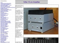 This amplifier uses two 60w Spectrian amplifier boards with the usual input and output hybrid coupler and combiner.
 -
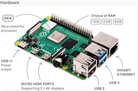 This resource is an online tutorial focused on setting up the Raspberry Pi for amateur radio applications. It covers the installation and configuration of various software packages tailored for digital communications and protocols, including _Packet Radio_ with Hamlib and Direwolf, as well as data modes like FLDigi and WSJT-X. The guide also details the integration of hardware components such as GPS clocks for time synchronization and real-time clocks for enhanced functionality. Users will find instructions for installing software like GPredict for satellite tracking and GQRX for software-defined radio (SDR) applications. The tutorial emphasizes practical steps, including the use of command-line inputs in the Raspberry Pi OS terminal, and provides troubleshooting tips for common issues such as faulty SD cards or insufficient power supplies. Operators are encouraged to explore various applications, including APRS iGates and WSPR beacons, to enhance their ham radio experience. The material is designed for licensed amateur radio operators with basic knowledge of electronics and computing.
 -
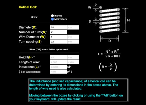 This online calculator will give as output the Inductance L of a coil, including the total lenght of the wire needed to wound the coil. As input, requires the Diameter, number of turns, wire diameter and turn spacing
 -
 This calculator ask as input diameter, lenght turn and frequencu and will return L and Q
 -
 Demonstrates the construction of a high-power 6-meter (50 MHz) amplifier, specifically designed for demanding modes like EME, TEP, and multiskip Es. It details the use of a _GU-43B_ tetrode in a grounded-cathode configuration, emphasizing the need for stabilized grid voltage and input capacitance compensation. The resource provides a comprehensive schematic, power supply design, and practical considerations for component sourcing, particularly for high-voltage and high-current sections. The builder achieved an output power of **1250 watts** with an anode current of 0.65 amperes and 3200 volts anode voltage. The article also covers the physical construction within a modified P6-31 enclosure, outlining the internal layout for RF and power supply sections, and includes photos of the completed unit. It highlights critical safety precautions for working with high voltages and reactive currents up to **20 Amperes** in the P-network.
 -
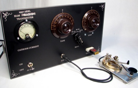 A homebrew radio transmitter project, based and inspired by the original 30 Watts input on 80 50 and 15 meters band transmitter by W11CP
 -
 Sixty-meter repeaters typically use a 1 MHz frequency separation between input and output, while 2-meter repeaters commonly employ a **600 kHz** split and 70-centimeter repeaters use a **5 MHz** offset. This article details the fundamental technical principles of amateur voice repeaters, explaining how they extend VHF/UHF communication range by receiving on one frequency and simultaneously retransmitting on another. It covers essential components such as receivers, transmitters, filters, and antennas, often situated on elevated locations for optimal coverage. The resource delves into the critical challenge of _desensing_—where the repeater's strong transmit signal overpowers its own receiver—and the engineering solutions employed, including antenna separation and the use of high-Q cavity filters. It also explores various control and timing systems, from basic squelch activation to more sophisticated microcontroller-based boards that manage functions like voice identification, time-out timers, and fault protection. Different access methods are discussed, including open access, toneburst, CTCSS subtone, and DTMF, each offering distinct advantages for managing repeater usage and mitigating interference. Furthermore, the article examines repeater linking, both conventional RF methods and modern internet-based solutions, highlighting how linking expands coverage and promotes activity across multiple repeaters or bands. It introduces less common repeater types such as 'parrot' repeaters, which use a single frequency and digital voice recording, and linear translators, capable of relaying multiple signals and modes simultaneously across different bands, often found in amateur satellites.
 -
 Online HB9CV antenna calculator, accept as input the desired resonating frequency and provides dimensions for spacing and length of each element, including boom and radiator diameter.
 -
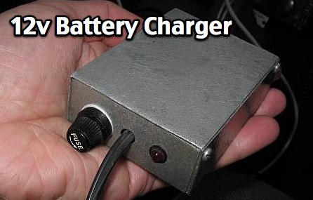 The charger described here is intended for charging small 12 Volt lead acid batteries
 -
 A 0-30 MHz step attenuator, constructed from switchable Pi attenuation pads, provides a practical tool for evaluating receiver sensitivity and calibrating S-meters. The design utilizes readily available 5% tolerance resistors, with values derived from paralleled components to achieve specific attenuation steps. A schematic (Fig 1) illustrates the circuit, including PCB pad shielding, while a table details required and actual resistor values, along with percentage differences. Measurements of voltage input versus output at various frequencies are used to calculate dB attenuation, presented in a graph (Fig 4). The resource includes formulas for determining output voltage from a known input and a comprehensive 0-40 dB voltage multiplier table, which is crucial for precise signal level management. The project also references external attenuator calculators and equations for further study. Photos (1-3) provide visual guidance for the assembled unit, showing bottom, top, and front views. The project emphasizes the use of **Pi attenuation pads** and **receiver sensitivity** evaluation, offering a hands-on approach to RF signal management.
 -
 RF is causing strange issues on the touch sensor buttons, controlling inputs, volume, channels on Samsung LCD TV. Solution is to disable front touch panel.
 -
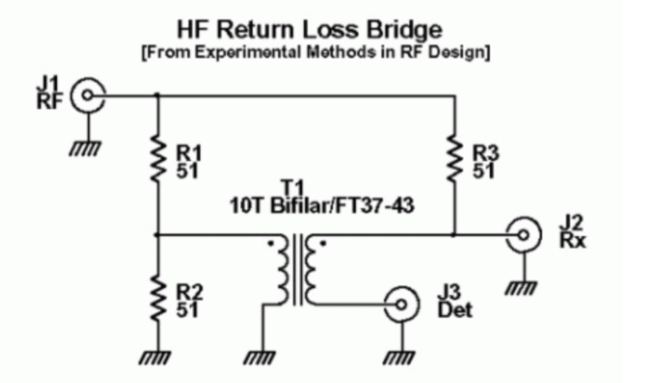 This Return Loss Bridge has been designed to characterize the input impedance of a receive strip, and the output impedance of a transmit strip
 -
 AN-SOF is a professional comprehensive software tool for the modeling and simulation of antenna systems. AS-SOF allows to describe antenna geometry, Choose construction materials, Describe the environment and ground conditions, Describe the antenna height above ground, Analize radiation pattern and front-to-back ratio, Plot directivity and gain, Analize input impedance and VSWR,Predict antenna bandwidth
 -
 Easy to use online Slim Jim antenna calculator. Input your frequency to automatically calculate the lengths of the different antenna parts.
 -
 One common semiconductor material, silicon, is far more widely used in electronics than germanium, partly because it can operate at much higher temperatures. Semiconductors are crystalline materials with electrical resistivity values between conductors and insulators, whose conductivity can be altered through _doping_ with impurities like arsenic or phosphorous to create N-type (excess electrons) or P-type (electron vacancies) materials. Semiconductor devices, such as diodes, transistors, and integrated circuits, leverage these properties to control electron flow in circuits. A diode, a two-terminal device with an anode and cathode, primarily permits current flow in one direction, making it useful as a rectifier to convert AC to DC. Specialized diodes include Zener diodes for voltage regulation and Light-Emitting Diodes (LEDs) that produce light when current passes through them. Logic circuits, fundamental to digital electronics, have binary inputs and outputs, performing functions like AND, OR, and NOT gates, and can be constructed from various binary devices including solid-state diodes and transistors. A transistor is an active semiconductor device with at least three terminals (base, emitter, collector), capable of amplifying current. Integrated circuits (ICs), often called chips, are electronic circuits built on a semiconductor substrate, typically silicon. ICs are classified by transistor type (bipolar or MOS) and integration scale: Small-Scale Integration (SSI) with fewer than 10 transistors, Medium-Scale Integration (10-100), Large-Scale Integration (LSI) with 100-1,000, and Very-Large-Scale Integration (VLSI) with more than **1,000** transistors. ICs can be analog, digital, or hybrid, offering virtually limitless functions.
 -
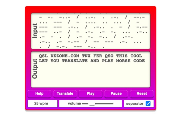 The online Morse code translator and decoder provides functionality for converting plain text into Morse code and decoding Morse code back into text. Users can input text directly into a designated box for translation to Morse, with the tool ignoring characters that lack a Morse equivalent. Conversely, Morse code can be entered using periods for dots and minus signs for dashes, requiring a single space to separate letters and a forward slash to delineate words. The interface also supports direct Morse input via a button, where a half-second pause separates letters and a 1.5-second pause separates words. The resource details the historical context of Morse code, noting its invention by _Samuel F.B. Morse_ in the 1830s for telegraphy, and its continued use by amateur radio operators for recreational purposes and emergency signaling, such as the **SOS distress signal**. Guidance on learning Morse code suggests using online translators for practice and listening to amateur radio transmissions. The tool offers an audio playback feature for translated Morse, allowing users to hear the code at various words per minute (WPM) settings. It also includes a visual chart to aid in memorizing the dot and dash sequences for the alphabet.
 -
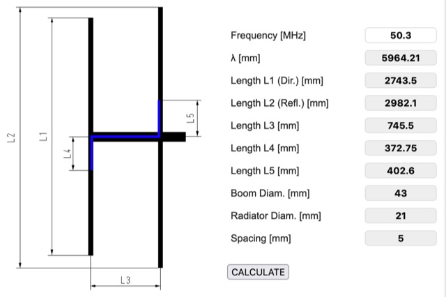
 A basic YAGI UDA online antenna calculator, accept as input frequency, number of elements, diameter of parasitic element and boom diameter. This online calculator will generate a basic design data including each element length and spacing.
 -
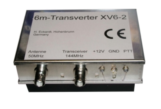 The XV4-10 is a linear transverter for the 4m band to be used with a 10m transceiver. Input frequency 29-30 MHz, output frequency 69.5-70.5 MHz
 -
 Operating in a Single Operator Two Radios (SO2R) setup, especially with beverage antennas, often exposes the receiving radio's front-end to significant RF energy from the transmitting radio. This resource details a practical, homebrew receiver protection circuit designed to mitigate this risk. The core of the design involves a non-inductive 2W 22 Ohm carbon composition resistor in series with the RX antenna line, followed by two stacks of four fast-switching diodes (e.g., _1N914_) configured in opposite polarizations. This arrangement effectively clamps the incoming voltage to approximately 2.8 V peak-to-peak, safeguarding sensitive receiver input components. The series resistor plays a crucial role by absorbing excess power, preventing the diodes from exceeding their current ratings and potentially failing open, which would leave the receiver unprotected. The author, _N4KG_, measured up to 50 watts of coupled power between 80M slopers on the same tower, highlighting the necessity of such protection. The design is presented as a cost-effective solution to prevent damage to receiver input transformers, with the author noting successful protection of a receiver even after a resistor showed signs of overheating. This simple circuit can be integrated via a transverter plug, offering a robust defense against high RF input.
 -
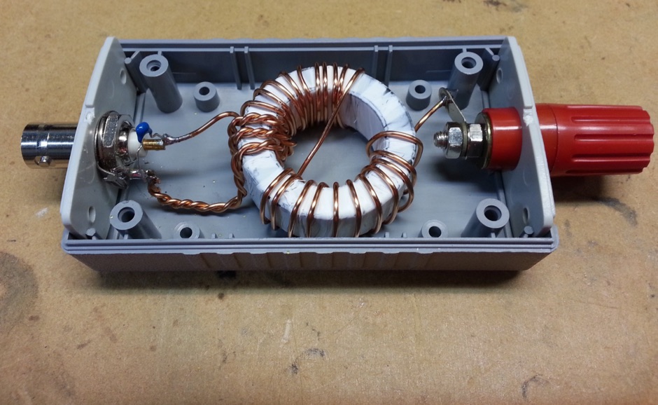 An end-fed half wave antenna matching unit made of 3:24 turns ratio on a FT140-43 toroid with a 150pF capacitor across the input.
 -
 256 memories enable the _AT-AUTO_ to recall settings across multiple bands, making it efficient for operators who frequently change frequencies. The tuner is compatible with various antennas and amplifiers, such as the Mercury LUX, and integrates seamlessly with radios like the FLEX 6400 using an RS232-USB connection. This integration allows the tuner to follow frequency changes without additional input, enhancing operational efficiency. Despite being out of production, the _AT-AUTO_ remains supported by Kessler Engineering, which offers firmware updates and repair services. The tuner features a cross-needle SWR meter, providing quick visual feedback during tuning. It also includes a QRO keyline circuit to protect amplifiers during tuning. Users appreciate the tuner's ability to track radios via CAT control, avoiding automatic tuning during QSOs, a common issue with other models. The _AT-AUTO_ is praised for its durability and performance, with many users noting its reliability over years of use. Its ability to handle legal limit power and its balanced line output make it a versatile choice for serious operators. Although it lacks some features like multiple coax outputs found in other models, its robust build and continued support make it a valuable tool for HF enthusiasts.
 -
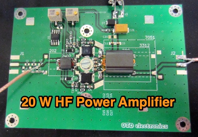 A HF power amplifier with a push-pull of AFT09MS015N. The (small-signal) gain of the amplifier is around 26 dB in the lower HF band and goes down to about 24 dB on the higher end and still around 21 dB at 50 MHz. Its input matching is relatively good at the lower HF and degrades above 10 MHz.
 -
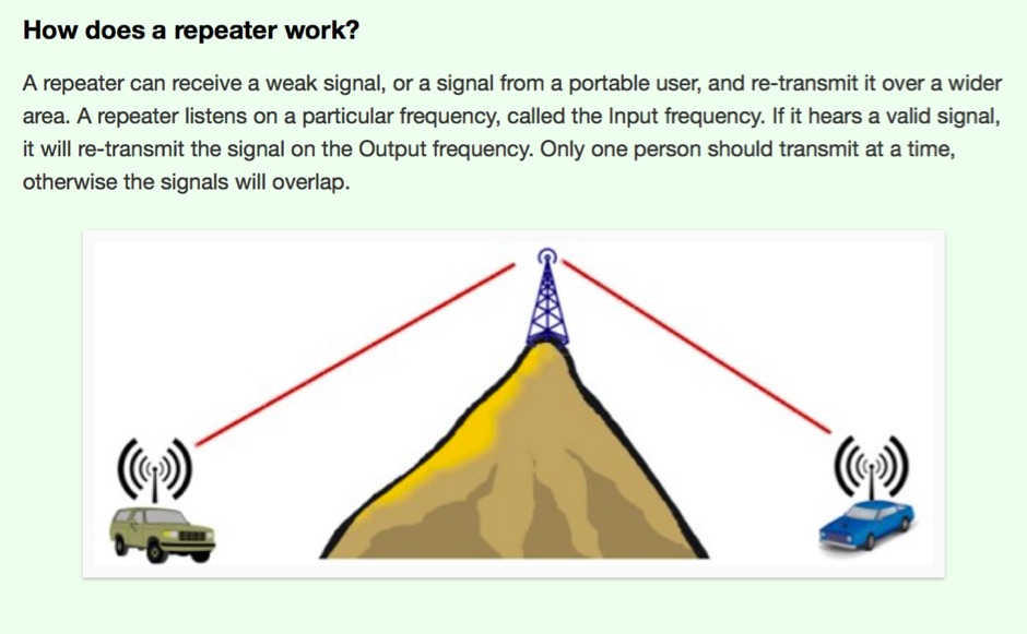 Amateur radio repeaters, often designated by an "R" number like _R6_ or _R5_, serve as crucial infrastructure for extending VHF/UHF communications range. This resource from Essex Ham explains the fundamental concept of a repeater, detailing how it receives on one frequency and simultaneously retransmits on another, typically with a 600 kHz offset for 2-meter repeaters. Understanding the input and output frequencies, along with the required CTCSS tone, is essential for successful access, ensuring your signal is processed and relayed across a wider service area. The article clarifies the importance of using the correct _CTCSS_ (Continuous Tone-Coded Squelch System) tone, often referred to as a sub-audible tone, to activate a specific repeater. It also touches upon the concept of _simplex_ operation versus repeater use, highlighting the benefits of repeaters for mobile and handheld transceivers. Proper operating procedures, such as listening before transmitting and keeping transmissions concise, are emphasized to maintain good amateur practice on shared repeater assets.
 -
 A home made Antenna Tuner made with a simple inductor and a few spare parts. Despite the title, the author succesfully tested this ATU with higher power inputs.
 -
 A 60-foot available space, for example, might necessitate a shortened multiband dipole array to cover 80, 40, and 15 meters effectively. This resource details the construction of such an antenna, combining full-size and coil-loaded dipoles on a single feedline. It addresses the common challenge of fitting multiple HF bands into restricted physical footprints, providing practical guidance for hams with smaller backyards or portable operations. The core of the offering is an interactive calculator that determines required loading coil inductance and dipole lengths for various amateur bands from 160m to 10m. Users input their available space, and the tool provides dimensions, coil turns, and an efficiency rating (Good or Fair) based on the antenna's electrical length relative to a quarter-wavelength. It also suggests suitable _PVC_ pipe diameters for coil forms. The article further illustrates a center feed-point assembly using an 18-inch section of 2-inch _PVC_ pipe, detailing eye-bolt spacing and coaxial connector installation. It emphasizes the importance of adequate spacing between parallel dipoles and offers customization options for the feed-point, including the addition of a _Balun_ for improved feedline isolation.
 -
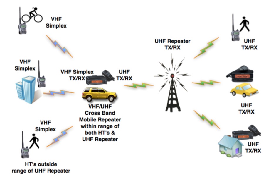 Crossband Repeating is a process where a Ham transmits one signal on one band (typically UHF), and it is received by another radio with a better antenna/power installation, and re-transmitted (typically on VHF) to another radio system, or a repeater. Everyday examples of cross-band repeaters are repeater receive sites that hear the input signals on 2m and retransmit those signals on a frequency higher than 220 MHz.
 -
 separate the K2 dot paddle input from the PTT
 -
 Enables operators to search the XR0ZRC DXpedition log online, a service facilitated by **Club Log**. This tool allows for rapid **QSO verification**, confirming contacts made with the XR0ZRC entity. Users can input their callsign and other contact details to ascertain if their signal report and time match the DXpedition's records, a critical step for award applications like DXCC. The platform offers a straightforward interface for checking log entries, which is particularly useful for those chasing new entities or band slots. It integrates seamlessly with the broader Club Log ecosystem, providing a reliable method for operators worldwide to confirm their DX contacts without requiring a login, reflecting the utility of real-time log updates in the amateur radio community.
 -
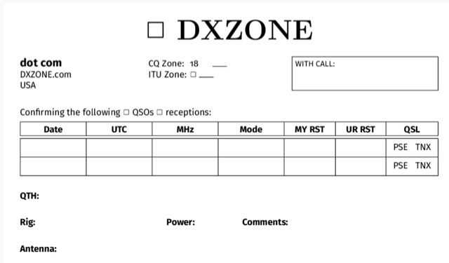 This app will generate a QSL card design based on the input paramters as a PDF. Fields marked by a * are required, but the rest are optional. The options at the bottom allow you to customise the look and feel of the QSL card. If you would like, you can also download the LaTeX source file and customise it.
 -
 Explains the fundamental purpose of a repeater, detailing how these automated relay stations overcome distance and terrain limitations for VHF/UHF communications. It traces the historical development from early Bell Telephone Labs "relay" stations in 1922 to Art Gentry, W6MEP's, pioneering K6MYK amateur radio repeater in the mid-1950s, which remains active today. The resource clarifies the distinction between simplex and duplex operation, including the unique function of a "parrot repeater" for single-frequency recording and playback. Delving into the internal workings, the guide breaks down a repeater into its core components: the antenna system, feedline (often _Heliax_ or hardline for minimal loss), duplexer, receiver, transmitter, and controller. It emphasizes the critical role of the duplexer in preventing receiver desensitization by isolating transmit and receive signals, even with distinct frequencies. The discussion highlights the importance of high-performance, durable antennas and low-loss feedlines, citing examples of equipment installed in the 1960s and 1970s that are still in perfect working order. Operating a repeater is also covered, with an explanation of frequency offset (e.g., the 600 kHz standard for 2 meters) and the function of _CTCSS_ (PL tone) for access. It outlines standard input/output offsets for various bands, from 6 meters to 23 centimeters, while noting regional variations. The guide also touches on features like autopatch and Digital Voice Recorders (DVRs), providing a solid foundation for understanding repeater technology and usage.
 -
 This page presents an online calculator tool for determining the dimensions of various HF wire antennas operating between 1.8-30 MHz. Users input their desired resonant frequency to obtain precise measurements for four popular antenna types: standard flat-top dipole, inverted Vee, quad loop, and equilateral delta loop. The calculator provides comprehensive measurements including leg lengths, minimum heights, horizontal spreads, and feedpoint distances. Accompanying the calculator are detailed technical explanations, construction notes, and installation guidelines for each antenna type, making it a practical resource for amateur radio operators building their own antennas.
 -
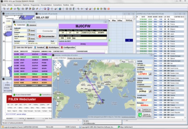 DXFile is a Windows shareware application designed for amateur radio operators, providing comprehensive log management capabilities. The software, developed in Pascal, facilitates real-time and deferred QSO entry, automatically populating fields like frequency, mode, and DXCC country based on user input and system time. It includes features for searching, modifying, and deleting QSO records, with options to sort logs by date, callsign, or entry order. The program offers various printing functions, including QSL card labels in multiple formats, and can generate standard logbook printouts. Beyond basic logging, DXFile integrates modules for tracking progress towards major operating awards such as DXCC, _IOTA_, WAZ, WAS, DDFM, and DIFM. It provides detailed summaries of contacts by band and mode, including graphical representations of HF traffic. A dedicated QSL Manager module assists in processing received QSLs, allowing users to mark confirmations and print multi-line QSL labels. The application also incorporates a DXCC list viewer, which can be updated to ensure accurate country and zone data for logging and award tracking. A distinctive feature is its HF propagation prediction module, which calculates optimal frequencies and signal levels for paths between **250 km** and **6000 km**, considering both E and F layer ionospheric conditions. This module helps operators determine the best times for long-distance contacts. Additionally, DXFile includes a _Web-Cluster_ interface, enabling connection to various DX cluster servers like DXLITE, DXSCAPE, and NC7J for real-time spot information.
 -
 This air-core solenoid style RF inductor calculator calculates the inductance, wire size, number of turns, and other parameters for an air-core solenoid inductor used in radio frequency (RF) circuits, based on user input of frequency, desired inductance value, and physical dimensions.
 -
 Home made 40 meter transceiver project. The receiver is a Progressive Receiver with a few modifications. The Transmitter is a modified MFJ Cub circuit. Includes schematic and circuit diagrams for Receive Input Filter, 3-Pole 500 Hz Cohn Filter and 7 MHz Double Tuned Bandpass Filter