Search results
Query: measure
Links: 267 | Categories: 10
Categories
- Antennas > Antenna Books
- Manufacturers > Test Equipment > Multimeters
- Technical Reference > Power Meter
- Technical Reference > Test Equipment > RF Probe
- Manufacturers > Test Equipment > Spectrum Analyzers
- Technical Reference > Standing Wave Ratio
- Manufacturers > SWR Meters
- Shopping and Services > Test equipment
- Technical Reference > Coax Cables and Connectors > Testing Coax Cables
- Manufacturers > Wattmeters
-
 Demonstrates a range of specialized radio frequency equipment and consulting services for amateur and professional applications. The offerings include _Vector-Finder_ direction finding antennas, various test equipment such as _gate dip meters_ and RF sniffers, and communications receiving adjuncts. Additionally, the company produces satellite antennas for weather satellite reception, voice amplification devices like the _Flex-Mike_, and custom prototype circuit boards. The company's product line addresses needs for precise RF measurement, signal detection, and specialized antenna systems, particularly for direction finding and satellite communications. Their historical association with National Radio (HRO) suggests a legacy in radio technology. The site also highlights a subsidiary, Sierra Mountain Products, which offers outdoor recreational gear, indicating a diversification beyond core RF manufacturing.
 -
-
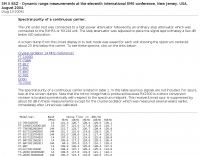 Comparison of FT-1000D FT-736R FT-817 FT-847 FT-897 IC-765 Orion TS-2000 Spectral purity of a continous carrier, of a SSB and CW signals
 -
 PEP RF output power measurement, and examples RF output power measurements
 -
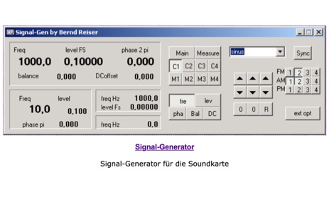 Windows signal function generator sotfware, offers 4 main channels, 4 modulators, 1 measurement generator, 1 frequency standard generator, Amplitude, phase and frequency modulation, can generates real band-limited signals
 -
 Details the construction of an **HF converter** designed by M1GEO, George Smart, specifically to extend the frequency range of the FunCube Dongle Pro (FCD) for amateur radio reception. The FCD natively covers 64 to 1,700 MHz, but this project enables reception from 0 Hz to 64 MHz by up-converting signals to the FCD's operational range. It employs a **double-balanced mixer** with a 100 MHz local oscillator (LO) to translate incoming HF signals; for instance, a 1 MHz signal appears at 101 MHz within the FCD's passband. The design incorporates a 7th-order Chebyshev low-pass filter with a 62 MHz cutoff frequency at the input to mitigate image frequencies, ensuring cleaner spectral presentation. George provides the schematic, PCB masks, and Gerber files for replication, noting that Far Circuits also offers PCBs. The resource includes test results for the low-pass filter and measurements of LO leakage, identifying -36.8 dBm at 100 MHz as a potential sensitivity concern. M1GEO discusses potential improvements, such as adjusting the mixer's LO drive, adding a balance pot, or incorporating a post-mixer high-pass filter to reduce LO breakthrough. Audio recordings from 40m and 17m demonstrate the converter's performance with WRplus SDR software.
 -
 How to measure the characteristic impedance of a unknown transmission line using MiniVNA
 -
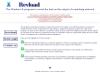 This graphics-intensive program reveals the load on the output of a matching-network, based on measurements of the components in that network. Adjust the network (tuner) for a flat input, measure or look up the network component values and you will immmediately see the R and jX values of the load on the network, presented as both a schematic with the component values and as a Smith Chart normalized to the specified system impedance.
 -
 Applied instruments manufactures test and measurement equipment for the broadband telecommunications industry. products include carrier generators, signal level meters, rf switches, spectrum analyzers and a return alignment system.
 -
 A RF Probe circuit for the RADIO frequency experimenter to check the presence of a RF signal and also to measure its strength
 -
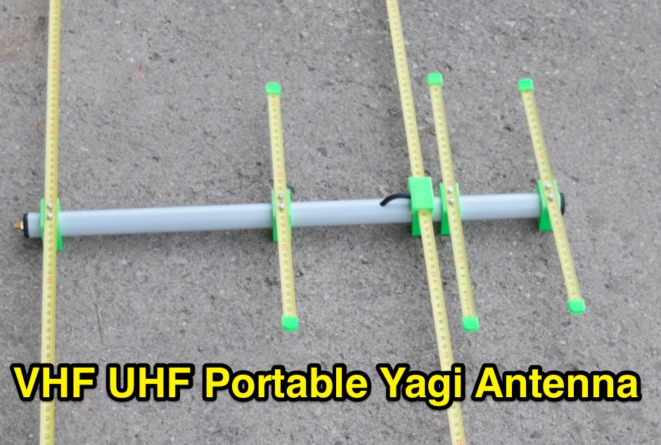 Tape measurement yagi. The longest part is 530 mm, easy fit to your backpack. Very easy and fast deploy. Great for SOTA and portable operation. Can be used in horizontal or vertical polarization. Based on DK7ZB design
 -
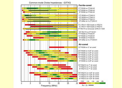 Chart that present results of impedance measurements made on a variety of common-mode choke implementations across the frequency range 1MHz to 30MHz by G3TXQ
 -
 New and refurbished test and measurement instruments
 -
 Gao engineering offers a wide range of affordable, popular and reliable rfid products, dsp, arm and other microprocessor evm and development boards, ides, universal programmers, emulators, dsp learning systems, micro-network terminals, test and measurement products for engineers.
 -
 A presentation of the Yagi Antennas, and other interesting tid-bits by Brian Mileshosky. The document provides an in-depth exploration of the Yagi-Uda antenna, detailing its historical development, design principles, and performance characteristics. Originally described in the 1920s, the Yagi antenna features a driven element and parasitic elements, including reflectors and directors, which collectively determine its behavior. The document highlights how element lengths, diameters, and spacing influence gain, impedance, and directivity. It also discusses the antenna's reciprocal nature and presents data on typical gain values for various element configurations. Additionally, the text covers practical considerations, such as the construction of a "Tape Measure Yagi" for amateur use, and touches on related antenna types like dipoles and their application in Near Vertical Incident Skywave (NVIS) communication.
 -
 Pc based test and measurement equipment and instrumentation: digital oscilloscope, logic analyzer and spectrum analyzer.
 -
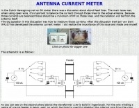
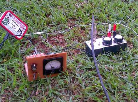 RF Current measurements on a Long Wire W3EDP antenna
 -
 Manufacturer of advanced electronic systems to measure such weather data as: wind speed, wind direction, wind chill, pressure, humidity, rainfall, and dew point.
 -
 How do two-wire reversible direction Beverages work, an excellent document that explains fundamentals of beverage antennas. This article details the design and performance of a reversible beverage antenna. Leveraging orthogonality between common mode and differential mode currents on a 2-wire line, this antenna facilitates independent reception from both ends. While common mode signals arrive and are summed on a transformer's secondary for common mode reception, differential mode signals induce anti-phase currents, providing individual reception. Various measurements explore impedance, transmission loss, and F/B ratio, highlighting the antenna's effectiveness and areas for improvement. Notably, increasing the antenna's height significantly improved performance.
 -
 Elecraft K3 vs. ICOM IC-781 vs. Kenwood TS-850: comparative Measurements and Experience
 -
 LEMO, established in 1946, specializes in high-performance interconnect solutions, offering an extensive range of over 50,000 circular connectors. Their product line includes the REDEL SP IP68 series, which features resin-free IP68 sealing for robust performance without complex potting processes. These connectors are critical for applications in medical, military, test and measurement, security, defense, and industrial sectors, ensuring reliable signal integrity in harsh conditions. The company designs, tests, and manufactures high-quality cable solutions, providing complete connectivity services such as custom cable assembly and signal integrity analysis. LEMO's solutions are integral to advanced scientific endeavors, as demonstrated by their use in CERN’s NA62 experiment for instrumentation and maintenance. LEMO's 80-year history, detailed in their anniversary publication, highlights their evolution from a Swiss family workshop to a global leader in connector technology. Their product finder tool assists customers in selecting appropriate connectors from their broad portfolio, which also serves audio-video, transportation, aerospace, and UAV applications.
 -
-
 Announces the retirement of Brand Electronics, a manufacturer specializing in **power meters** and various ham radio accessories, effective 2025. The company has served the amateur radio community for over 35 years, providing equipment for station setup and operation. The product line historically included accessories compatible with major transceivers from Icom, Yaesu, and Kenwood, alongside components and technical references for homebrew projects. Their offerings supported accurate RF power measurement, crucial for optimizing antenna systems and ensuring legal limit compliance. This notice serves as a final update regarding the company's operational status, marking the cessation of manufacturing and sales activities. The site provides no further details on product support or inventory liquidation.
 -
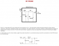 This RF probe circuit allows RF to be measured in the presence of DC
 -
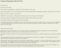 KC5M frequency measurement with yaesu ft-920
 -
 Since 1956, E-Z-Hook has been manufacturing electronic test accessories used for test and measurement purposes throughout multiple industries. Test probes, multimeters, coax cables, adapters
 -
 NRSC AM bandwidth measurements with the loop antenna
 -
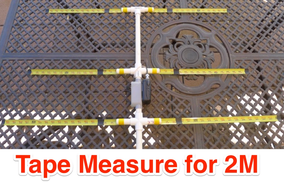
 A 7 dB directional gain is reported for this portable VHF Yagi antenna design, which utilizes cut metal tape measure sections for its elements. The resource details the construction process for a 2-meter band antenna, emphasizing its ease of build and portability. It specifically mentions the design's suitability for radio direction finding (RDF), fox hunting, and communication with satellites and the International Space Station (ISS), highlighting its practical applications for amateur radio operators. The construction cost is estimated at under $20, with potential for even lower expense if salvaged materials like old tape measures and PVC pipes are used. The article references _Joe Leggio's_ (WB2HOL) original design, noting specific alterations made by the author. It also compares this design to other DIY Yagi antennas, including _FN64's_ 2-meter band and _manuka's_ 70-cm band tape measure Yagis, underscoring its unique combination of simplicity, portability, and effective performance with a 1:1 SWR achievable on the 2-meter band.
 -
 A Tape Measure Beam Antenna for Radio Direction Finding based on WB2HOL design.
 -
-
 Gold Line, a manufacturer, provides a range of professional audio test and analysis equipment, including specific products like the **ZM1 Impedance Meter**, which is relevant for amateur radio operators needing to characterize antenna systems. The site also lists various noise sources and microphones, such as the TEF04 Mic, indicating a focus on audio signal integrity and measurement. The resource details contact information for repairs, calibration, quotations for specific products like the ZM1 and ZM1P, and technical support, with distinct email addresses and phone numbers provided for each function. This structured contact approach facilitates direct engagement with the appropriate department for specific inquiries. Operational changes effective March 1, 2019, are noted, directing users to VLDESIGN for repair and calibration, and to Partha Chen for ZM1/ZM1P quotations. Louis Pittsley is designated for technical support, with a general inquiry phone number also available, outlining the company's support infrastructure.
 -
 Mobile RFI, often manifesting as persistent noise in the receiver even with the antenna disconnected, frequently originates from the vehicle's power supply system. This guide details systematic troubleshooting steps, beginning with isolating the radio from the car's 12-volt supply to confirm the power system as the noise source. It emphasizes the critical importance of drawing power directly from the battery using **heavy gauge wire**, bypassing the fuse block to leverage the battery's natural capacitance for RFI suppression and ensuring a solid RF ground. Proper routing of power lines through the firewall is also covered, advocating for dedicated grommeted holes to prevent inductive coupling from other wiring harnesses. The article stresses the necessity of fusing both positive and negative leads from the battery, a crucial safety measure to prevent damage to the rig and mitigate high-current risks should the battery's engine block ground become compromised during service. Addressing **alternator whine**, a common high-pitched noise that varies with engine speed, the resource suggests checking battery connections and the alternator-to-battery harness for looseness or corrosion. It also mentions the utility of adding an external RF noise suppression capacitor in parallel with the alternator's internal capacitor for enhanced filtering, and the effectiveness of commercially available in-line power supply filters.
 -
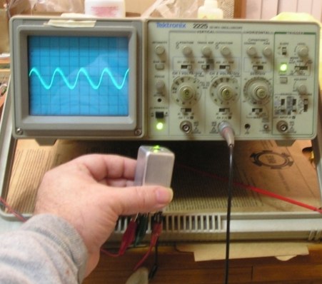 Build you own RF probe, measure the level of RF voltage present at a particular point.
 -
 Gage applied technologies designs and manufactures high-speed data acquisition systems, high-speed digitizers in pci / cpci / pxi or pc oscilloscopes, providing utmost measurement fidelity for high frequency signals.
 -
 SWR analysis of an Alpha-Delta DX-LB Plus antenna, configured as an inverted-V with the apex at 40 feet and ends at 15 feet, reveals specific performance characteristics across the HF spectrum. Measurements were conducted using a RigExpert AA54 antenna analyzer, scanning from 0.100 MHz to 54.000 MHz to capture full-range SWR plots. The antenna exhibits notably narrow bandwidths on 80 meters and 160 meters, attributed to its loading coils, necessitating precise tuning for optimal operation within these bands. Conversely, the Alpha-Delta DX-LB Plus demonstrates excellent SWR across the entire 40-meter band, indicating a broad resonance. Performance on 10 meters also shows favorable SWR, though tuning to a desired operating frequency is still recommended for peak efficiency. The article details the methodology and tools employed, building upon a previous "Part 1" analysis of a G5RV antenna, providing a comparative context for antenna evaluation. Practical experience with this multi-band antenna, particularly its loading coil design, highlights the challenges in achieving desired SWR across all bands without specific adjustments. The author's subsequent plans involve replacing the Alpha-Delta DX-LB Plus with a homebrewed 80-40-20-10m parallel **fan-dipole**, aiming for improved resonant characteristics.
 -
 Used electronic test and measurement equipment
 -
 Demonstrates the complete design and development process for a **Low Noise Microwave Amplifier** (LNA), beginning with conceptual design and progressing through prototyping. The tutorial series covers the initial stages of a single-ended first gain stage, focusing on critical parameters such as noise figure, gain, and stability. It systematically details the theoretical underpinnings and practical considerations for achieving optimal performance in microwave frequency applications. This resource provides a structured approach to LNA construction, enabling radio amateurs and RF engineers to understand the iterative steps involved in realizing high-performance receive-side amplification. It offers insights into component selection, impedance matching networks, and the measurement techniques required to validate design specifications, particularly for **microwave** band operation where noise performance is paramount.
 -
 The WB5RVZ Genesis Radio G40 build log documents the construction of a 5W QRP 40m SDR transceiver kit, detailing each phase of assembly from power supply to RF filtering. It provides specific component lists, parts placement diagrams, and testing procedures for stages like the local oscillator, Tayloe detector, and RX op-amps. The resource highlights discrepancies between documentation versions and offers practical advice for builders, including a "virtual build" approach to preemptively address potential ambiguities in component identification and placement. It also addresses a specific "VK6IC Fix" for early board revisions, involving trace cuts and jumper wires for improved performance. The build log presents measured voltages and expected current consumption for various stages, such as the 4.9-5.0 Vdc on the 5V rail and under 100mA for RX current. It outlines critical adjustments like image rejection tuning, a common procedure for direct conversion receivers. The resource also includes practical tips for handling components like the 2N3866 transistor and its heatsink, emphasizing pre-assembly. It details the winding of two 1.45 uH toroidal inductors on T50-6 cores with 17 turns of #20 AWG wire, crucial for the RF path.
 -
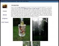
 Constructing a dip oscillator provides radio amateurs with a fundamental piece of test equipment for resonant circuit analysis. This particular design, adapted by VK3YE from a concept by _Drew Diamond VK3XU_, details a practical build using readily available components. The unit incorporates four plug-in coils, covering a frequency range from **2.6 MHz to 55 MHz**, mounted on 5-pin DIN plugs for versatility. A salvaged two-gang air dielectric variable capacitor, fitted with a vernier reduction drive, serves as the tuning mechanism, with the smaller gang optimizing bandspread at higher frequencies. In practical application, the dip oscillator is used by setting the meter needle to approximately two-thirds scale. When the instrument's coil is brought near a tuned circuit under test, a noticeable dip in the meter reading indicates resonance. This allows for precise measurement of resonant frequencies in antennas, filters, and other RF circuitry, proving invaluable for homebrewing and troubleshooting. The design emphasizes short wire runs for stable operation, particularly at the higher end of its operational range.
 -
 This project details the construction and testing of a M0PLK Delta Loop antenna for the 20-10m ham radio bands. Inspired by positive reviews highlighting its reduced local QRM compared to Cobweb antennas, the author built the antenna using aluminum tubes, DX-Wire FS2 wire, and a 1:4 balun. A mix of custom 3D-printed parts and careful assembly ensured stability and performance. Initial VSWR measurements met expectations, and test QSOs demonstrated success across multiple bands. Future enhancements include adding a lightweight, remote-controlled rotator for directional capabilities.
 -
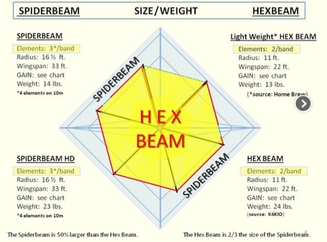 Differences of Hex Beam and Spiderbeam antennas designs, performance and measurements, rotor considerations when using this two kind of antennas
 -
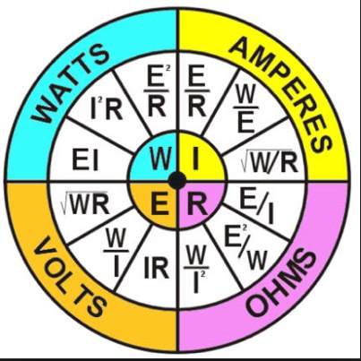 Both Watts and Volt-Amperes are units of measurement for electrical power. Learn what is the difference
 -
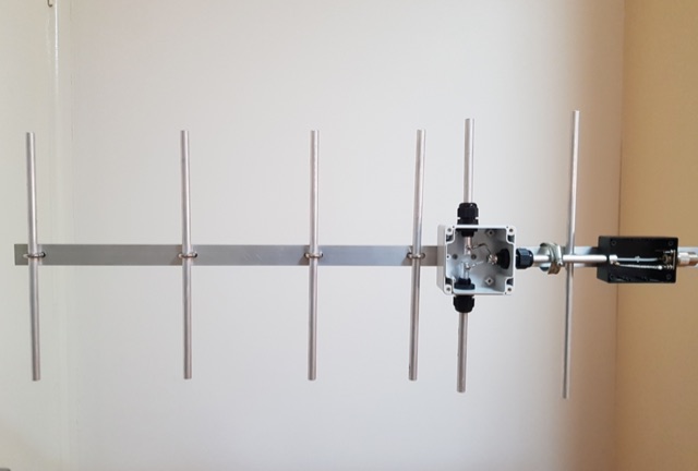 A fun little project I did over a couple of days was making this little 6 element yagi for 70cm. There are so many designs and ways one can do this so after some reading of different designs and measurements
 -
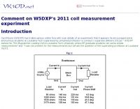
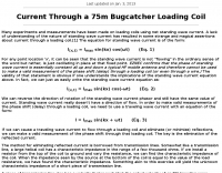 About experiments and measurements on loading coils using net standing wave current
 -
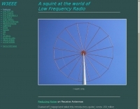 A squint at the world of LF This website was initially thrown together to provide ready availability to data being collected from the measurement of a transatlantic LF (Low Frequency) path.
 -
 Specialized in manufacturing measurement instruments for more than 25 years. Clamp meter, digital multimeter, analog panel meter, thermometer, and led panel meter
 -
 1500 watts PEP SSB is the power handling capability of the MFJ-989C HF Antenna Tuner, a popular choice among amateur radio operators. Users have shared a wide range of experiences, with some praising its durability and performance over decades of use, while others criticize its build quality and accuracy. The tuner features a built-in dummy load, SWR-wattmeter, and a balun for balanced line feeders, making it versatile for various antenna setups. However, discrepancies in RF power readings and SWR measurements have been noted, with some users finding the dual scale meter to be off by about 20% compared to a Bird wattmeter. Long-term users report that the MFJ-989C performs well with proper antenna setups, but caution against tuning at high power without initial adjustments at lower power levels. Some have experienced issues such as arcing when exceeding 400 watts, while others have had no problems even at higher power levels. The roller inductor and capacitors are functional, though some users have had to perform maintenance like tightening screws or cleaning components to ensure reliable operation. Despite mixed reviews, the MFJ-989C remains in production, suggesting continued demand. It's a tuner that requires careful handling and possibly some DIY fixes to achieve optimal performance.
 -
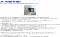 Measure the AC current flowing through your appliances
 -
 The cable testing approaches discussed in this article gives an idea about the electrical characteristics of a coaxial cable. Velocity of Propagation, Characteristics Impedance, Return Loss Measurement and more
 -
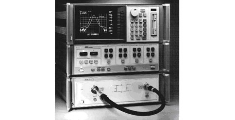
 Constructing a high-performance RF spectrum analyzer up to 1000 MHz requires careful attention to component selection, shielding, and circuit isolation. This resource details a project that improves upon the _Spectrum Analyzer for the Radio Amateur_ design by Wes Hayward (W7ZOI) and Terry White (K7TAU), incorporating ideas from Scotty Sprowls' project, particularly his 1013.3 MHz IF bandpass cavity filter. The analyzer utilizes a Mini-Circuits SRA-11 mixer with a sweeping local oscillator from 1013 to 2013 MHz, feeding into a 4-pole copper pipe cavity filter. The design employs a second SRA-11 mixer with a fixed 1024 MHz LO to produce a 10.7 MHz final IF. This signal then passes through narrowband resolution filters and is processed by Analog Devices AD603 and AD8307 ICs for IF amplification and logarithmic detection, driving an oscilloscope in X/Y mode. The project emphasizes modular construction, using salvaged components and double-sided FR4 material for PCBs, with critical notes on minimizing spurious images through effective shielding and proper voltage regulation for each module. Key components include a Z-Communications V585ME48 VCO for the first LO and a Z-Comm V583ME01 VCO controlled by a Motorola MC145151 PLL for the second LO. An optional Hittite HMC307 step attenuator and K&L 5L121-1000/T5000-O/O low-pass filter manage RF input. Tuning procedures for the 10.7 MHz IF resolution filter are also detailed, showing before-and-after spectrum views.