Search results
Query: noise
Links: 231 | Categories: 6
-
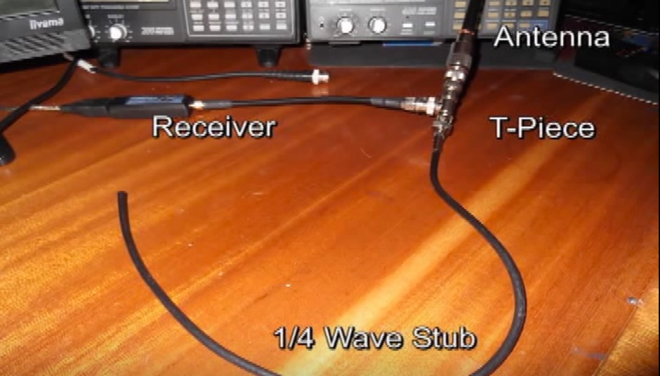 Cutting out the noise using a simple coax filter to improve the poor front end filtering
 -
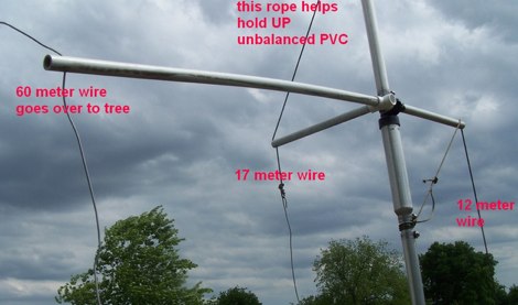 6BTV (or 5BTV or 4BTV) mod for 12 and 17 meter bands, how to make a 7BTV or 8BTV or 9BTV, easy and cheap
 -
 Noise foundamentals. Radio frequency interference noise.
 -
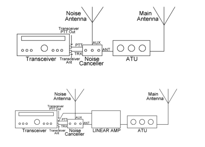
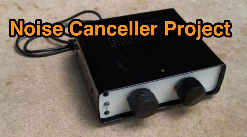 This project was intended to accompany the stealth antenna project. Author want to see how effective a noise canceller could be in reducing the background noise floor when attic / stealth antennas are being used.
 -
 Optimizing weak signal reception on the HF bands, particularly in the presence of strong local QRM, often necessitates specialized receiving antenna systems. This resource details the _HI-Z Antennas_ product line, focusing on phased vertical arrays designed for superior noise rejection and directivity. It covers components such as the 4-Square and 8-Element array controllers, which allow for rapid switching of receive patterns, and dedicated low-noise preamplifiers to improve system sensitivity. The site also presents various bandpass filters, crucial for mitigating out-of-band interference and enhancing the dynamic range of the receiver. The HI-Z systems are engineered to provide significant front-to-back and side rejection, often yielding **20-30 dB** of attenuation to unwanted signals, which is critical for DXing and contesting. Users can achieve a notable reduction in local noise, allowing for the discernment of signals that would otherwise be buried. The array controllers facilitate quick pattern changes, enabling operators to null out interference or peak weak signals from distant stations, effectively extending the reach of their receive capabilities by improving the signal-to-noise ratio.
 -
 Understanding the operational impact of Broadband over Power Line (BPL) on amateur radio communications is crucial for any radio amateur, especially given the potential for significant radio frequency interference (RFI). This ARRL tutorial delves into the technical aspects of BPL, explaining how the technology operates by transmitting data over existing electrical power lines, which can inadvertently radiate broadband noise across various amateur bands. My own field experience, particularly on the lower HF bands, has often involved tracking down noise sources that exhibit characteristics consistent with BPL emissions, making this a pertinent topic for maintaining clear receive conditions. The resource further details the specific FCC rules and regulations implemented to restrict BPL deployment. These regulations aim to protect licensed radio services, including amateur radio, from harmful interference. It outlines the technical standards and operational limitations imposed on BPL systems to minimize their impact on the electromagnetic spectrum, a critical aspect for contesters and DXers alike. For those engaged in RFI mitigation, the tutorial provides a foundational understanding of the regulatory framework that can be leveraged when addressing BPL-related interference issues. It serves as a valuable reference for hams seeking to comprehend the technical challenges and regulatory solutions surrounding this pervasive noise source.
 -
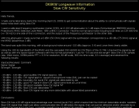 DK8KW laboratory tests to get some indication about the ability to communicate with signals below noise level using Slow-CW.
 -
 Memory recorders, Power meters, testers and multimeters, noise testers, signal generators
 -
 Yaesu FT-817 noise blanker improvement
 -
 The _Sci.Electronics FAQ: Repair: RFI/EMI Info_ document, authored by Daniel 9V1ZV, provides a detailed analysis of computer-generated RFI/EMI, focusing on its impact on radio reception. It identifies common RFI sources such as CPU clock rates (e.g., 4.77 MHz to 80 MHz), video card oscillators (e.g., 14.316 MHz), and even keyboard microprocessors, all of which generate square-wave harmonics across HF and L-VHF regions. The resource outlines a systematic procedure for pinpointing RFI origins, including disconnecting peripherals and using a portable AM/SW receiver with a ferrite rod antenna to localize strong interference sources. The document categorizes RFI mitigation into shielding, filtering, and design problems, offering practical solutions for each. It recommends applying conductive sprays like _EMI-LAC_ or _EMV-LACK_ to plastic casings of radios, monitors, and CPUs to create effective Faraday cages, emphasizing proper grounding and avoiding short circuits. For filtering, the guide suggests using line filters, ferrite beads, and toroids on power and data lines, and small value capacitors (e.g., 0.01 uF for serial/parallel, 100 pF for video) to shunt RFI to ground. It also discusses the use of bandpass, high-pass, low-pass, and notch filters on the receiver front-end or antenna feed to combat specific in-band noise.
 -
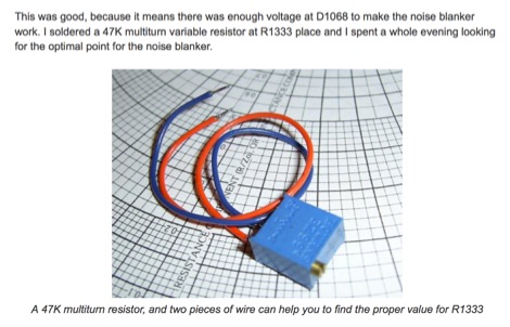 A modification to improve quality of built-in FT-817 Noise Blanker
 -
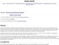 Radio Interferences, QRN, or noise, information by W8JI
 -
 KB9AMG's Top WSPR Spots presents a focused online tool for monitoring **2-way WSPR reports**, specifically detailing propagation data from February 2026 through March 2026. This resource aggregates _WSPRnet_ data, allowing radio amateurs to observe weak signal propagation conditions across various bands. The interface is straightforward, presenting callsigns, frequencies, signal-to-noise ratios, and distances for each reported contact, which is crucial for understanding current band openings and signal paths. The utility of this WSPR spotter lies in its ability to quickly visualize global propagation. Users can identify active stations and assess signal viability over long distances, with reports often showing contacts spanning thousands of kilometers. For instance, a typical WSPR report might indicate a signal from Europe reaching North America with a _SNR_ of -25 dB, demonstrating effective low-power communication. This data is invaluable for planning DX operations or evaluating antenna performance under actual propagation conditions.
 -
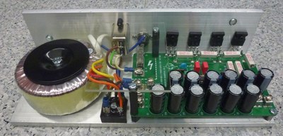 A project of a linear regulated for low noise power supply 16v, 10A
 -
 It is not always possible to tackle the sources of local QRM. What remains is trying to reduce the noise level by means of your antenna system. Learn how to reduce QRM and understand how cancell noises.
 -
 This is perhaps the most important parameter in many oscillators and it deserves an in-depth discussion on what it is, how it affects a system and how it can be minimised in an oscillator design.
 -
 Friis-It NF is the first iPhone OS based application that allows you to calculate noise figure, system sensitivity, and cascaded gain for an RF Receiver system
 -
 137 kHz propagation analysis details ground wave and sky wave mechanisms, drawing heavily from **CCIR Rec. 368-6** for ground wave field strength predictions and **CCIR Rep. 265-7** for sky wave modeling. The resource presents field strength values for 1 W ERP at varying distances, considering ground conductivity and permittivity for ground wave, and ionospheric height (70km daytime, 90km nighttime) for sky wave. Key factors like ionospheric focusing (factor "D"), reflection coefficient ("RC"), and antenna ground pattern factors ("Ft", "Fr") are quantified for 137 kHz, enabling calculation of sky wave field strength. Practical coverage ranges are derived for 137 kHz, showing useful ground wave coverage up to 1600 km over seawater and 1100 km over average ground, assuming a -9 dBuV/m noise floor. Sky wave coverage extends beyond 2200 km during night-time and winter daytime, but is negligible during summer daytime at solar minimum. The document also compares ground wave and sky wave strengths, identifying crossover distances at 550 km (night-time), 750 km (winter daytime), and 1250 km (summer daytime), where interference fading can occur. Adjustments for solar maximum conditions are provided, indicating 2-11 dB higher sky wave values depending on distance and season.
 -
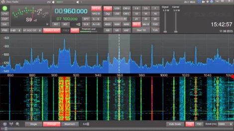 Zeus Radio program is designed specifically for the ZS-1 transceiver and supports all the basic functions (RIT, XIT, SPLIT, Noise Reduction, Auto Notch Filter, etc.) in order to work in the broadcast brought only pleasure. Zeus Radio works also with Hermes, Anan, Afedri, Red Pitaya, HiQSDR, Odyssey, Extio, RTL-SDR, Peaberry, Winradio, SDR-IQ, Afedri
 -
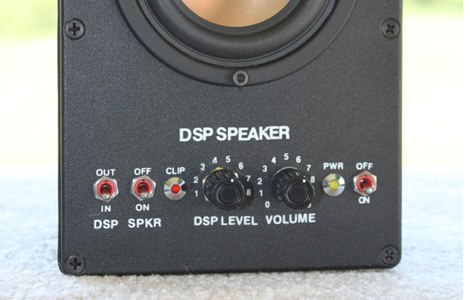 Build this noise reducing system to enhance audio of your speaker. A project by kg4jjh
 -
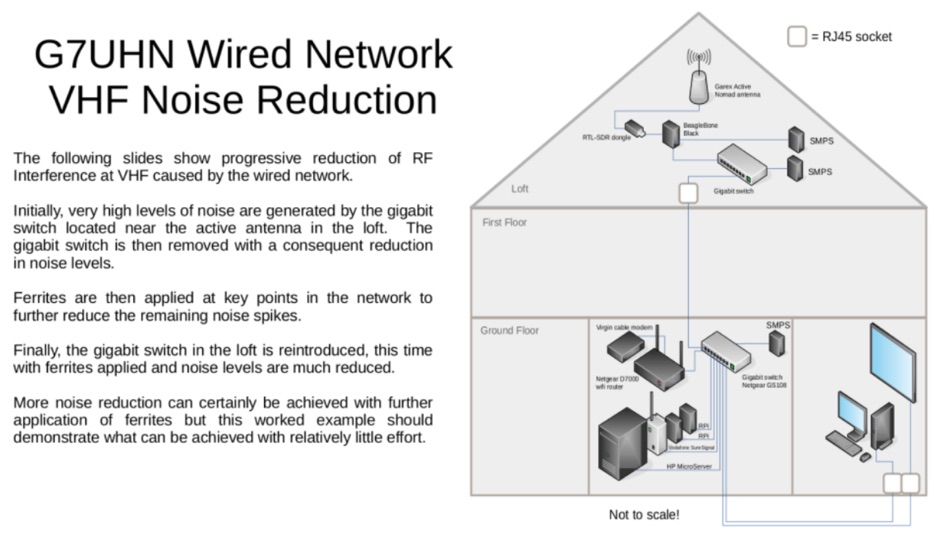 How to reduce and eliminate the RF interference at VHF caused by the wired network
 -
 A 102-inch vertical whip, commonly a CB antenna, forms the core of this low-profile 10-meter antenna design, optimized for the 28 MHz band. The construction details specify three 8-foot radials made from scrap wire, connected to a common point. This simple yet effective setup is designed for ease of construction and deployment, making it accessible for operators with limited space or materials. The design emphasizes using readily available components, including PVC pipe for the mast and a SO-239 connector for the feedline, ensuring a straightforward build process for a resonant quarter-wave vertical. Field results indicate that this antenna provides good performance for local and DX contacts on 10 meters, despite its compact footprint. The author, N8WRL, shares practical insights into its construction and tuning, highlighting its suitability for temporary or permanent installations where a full-sized antenna might be impractical. Comparisons to more complex designs suggest that this low-profile vertical offers a respectable signal-to-noise ratio and effective radiated power for its size, proving that simple designs can yield satisfying on-air results.
 -
 Demonstrates the product line of CAIG Laboratories, focusing on specialized contact cleaners and lubricants essential for maintaining electronic components. Key products include **DeoxIT**, designed for deoxidizing and protecting electrical connections, and **DeoxIT Gold (ProGold)**, formulated to enhance conductivity and provide long-lasting protection on plated surfaces. Details the application of these solutions across various electronic devices, from audio equipment to critical ham radio gear, ensuring optimal signal integrity and component longevity. The product range also features **DeoxIT Faderlube (CaiLube MCL)**, specifically engineered for conductive plastic and carbon-based controls, mitigating wear and improving tactile feel. Explains how proper contact maintenance with these products can prevent intermittent connections, reduce noise, and extend the operational life of switches, potentiometers, and connectors in both commercial and amateur radio applications.
 -
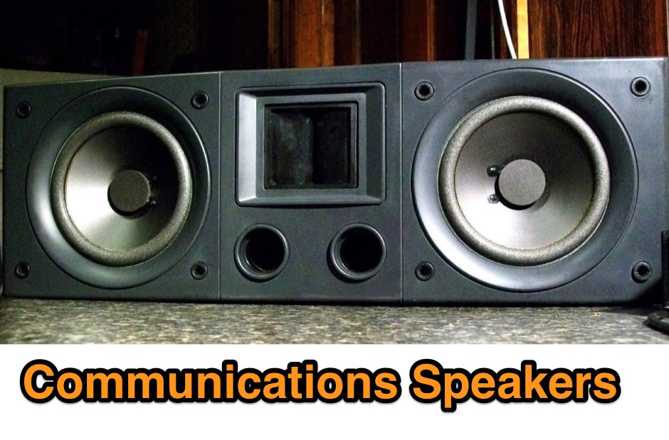 Have you searched and searched for a good speaker for your ham radio? That perfect speaker that would let you hear voices through the noise and static without hiss?
 -
 An interesting article on grounding and receiver noise
 -
 Gold Line, a manufacturer, provides a range of professional audio test and analysis equipment, including specific products like the **ZM1 Impedance Meter**, which is relevant for amateur radio operators needing to characterize antenna systems. The site also lists various noise sources and microphones, such as the TEF04 Mic, indicating a focus on audio signal integrity and measurement. The resource details contact information for repairs, calibration, quotations for specific products like the ZM1 and ZM1P, and technical support, with distinct email addresses and phone numbers provided for each function. This structured contact approach facilitates direct engagement with the appropriate department for specific inquiries. Operational changes effective March 1, 2019, are noted, directing users to VLDESIGN for repair and calibration, and to Partha Chen for ZM1/ZM1P quotations. Louis Pittsley is designated for technical support, with a general inquiry phone number also available, outlining the company's support infrastructure.
 -
 This page describes how to make the inexpensive Ten-Tec model 297 noise blanker work with the Drake R-4C receiver.
 -
 Mobile RFI, often manifesting as persistent noise in the receiver even with the antenna disconnected, frequently originates from the vehicle's power supply system. This guide details systematic troubleshooting steps, beginning with isolating the radio from the car's 12-volt supply to confirm the power system as the noise source. It emphasizes the critical importance of drawing power directly from the battery using **heavy gauge wire**, bypassing the fuse block to leverage the battery's natural capacitance for RFI suppression and ensuring a solid RF ground. Proper routing of power lines through the firewall is also covered, advocating for dedicated grommeted holes to prevent inductive coupling from other wiring harnesses. The article stresses the necessity of fusing both positive and negative leads from the battery, a crucial safety measure to prevent damage to the rig and mitigate high-current risks should the battery's engine block ground become compromised during service. Addressing **alternator whine**, a common high-pitched noise that varies with engine speed, the resource suggests checking battery connections and the alternator-to-battery harness for looseness or corrosion. It also mentions the utility of adding an external RF noise suppression capacitor in parallel with the alternator's internal capacitor for enhanced filtering, and the effectiveness of commercially available in-line power supply filters.
 -
 Demonstrates the complete design and development process for a **Low Noise Microwave Amplifier** (LNA), beginning with conceptual design and progressing through prototyping. The tutorial series covers the initial stages of a single-ended first gain stage, focusing on critical parameters such as noise figure, gain, and stability. It systematically details the theoretical underpinnings and practical considerations for achieving optimal performance in microwave frequency applications. This resource provides a structured approach to LNA construction, enabling radio amateurs and RF engineers to understand the iterative steps involved in realizing high-performance receive-side amplification. It offers insights into component selection, impedance matching networks, and the measurement techniques required to validate design specifications, particularly for **microwave** band operation where noise performance is paramount.
 -
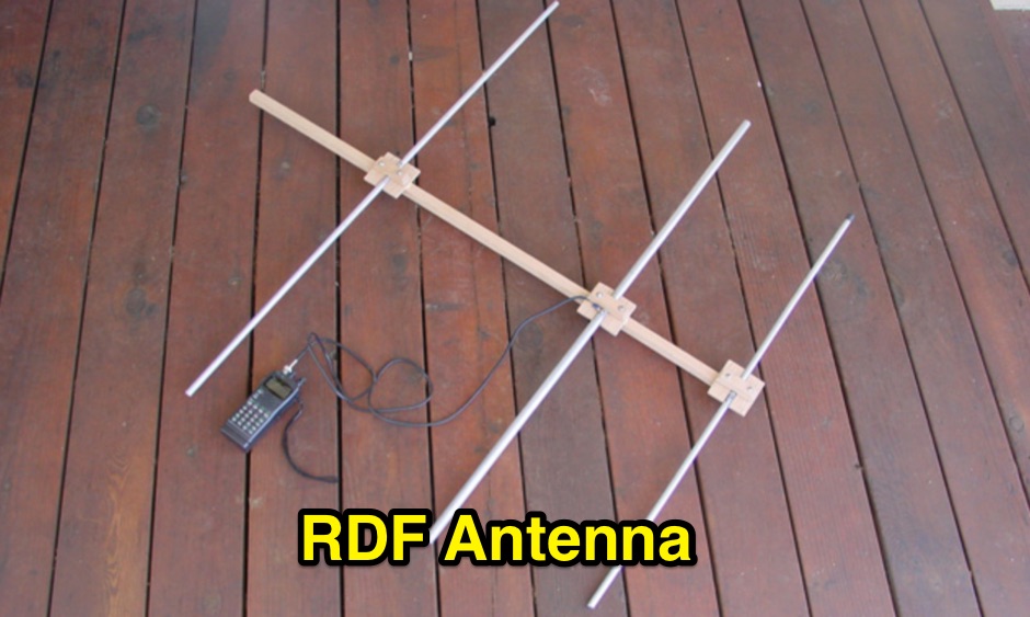 How to homemade antenna to be used with a handheld on the aircraft band to locate noise sources
 -
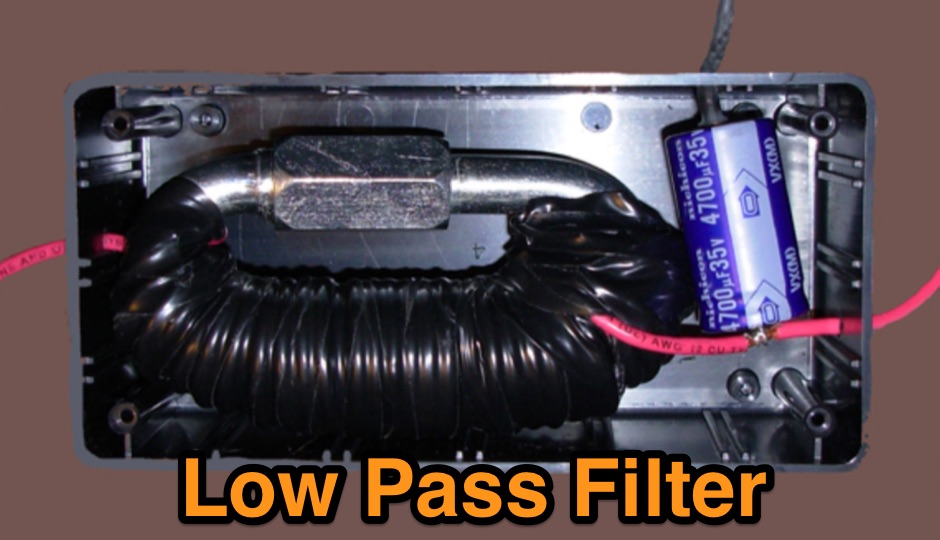 How to create a low pass filter able to reduce or even remove the noise generated from your car or truck alternator
 -
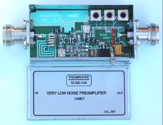 An home made low noise preamplifier project for 144 MHz, with detailed circuit diagram. The VLNA-144 preamplifier has been Published on DUBUS 4 2019
 -
 Article on Phase-cancellation of noise on 2m band
 -
 Noise Canceller kit originally developed about 1989 by G4WMX and GW3DIX and improved by DK9NL and DG0KW.The VK5TM Noise Canceller is another version of the design, with the HF Vox circuit removed and a couple of other minor changes, including the use of SMD JFETs and a double-sided pcb.
 -
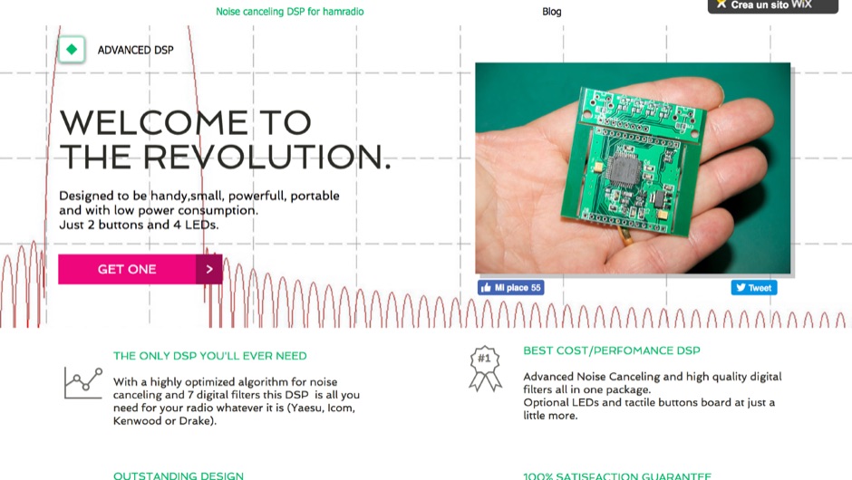 Noise canceling DSP for ham radio good for Icom, Yaeu, Kenwood and any kind of radio
 -
 The Kenwood TS-870S HF transceiver features two state-of-the-art 24-bit 20 MIPS DSP chips, providing over 100dB out-of-passband attenuation and CW bandwidth adjustable to 50 Hz. It operates across 160-10 meters with 100 watts output, incorporating digital filtering, a beat canceller, and 100 memory channels. The radio also includes a transmit equalizer, RX antenna input, and a K1 Logic Keyer, enhancing signal processing and operational flexibility for amateur radio operators. Advanced capabilities include IF stage DSP, dual noise reduction, and an auto notch filter, all contributing to superior signal reception and clarity. The TS-870S offers a variable AGC, voice equalizer, and an RS-232C port for computer control, with Windows™ software supplied. Its built-in automatic antenna tuner functions on all bands for both transmit and receive modes, streamlining station setup and operation. Available accessories such as the DRU-3A digital recording unit, SO-2 high stability crystal oscillator, and VS-2 voice synthesizer option further extend the transceiver's utility. The unit requires 13.8 VDC at 20.5 Amps and is supplied with an MC-43S hand microphone, making it a comprehensive station component.
 -
 Fifty-three digital modes, including PSK31, RTTY, and JT65, are explored in this resource, providing detailed descriptions of their underlying technologies and typical use cases. It covers error correction methods like ARQ in PACTOR and FEC in JT65, alongside modulation schemes such as FSK and PSK. The content highlights the evolution of digital communication from traditional TNC-based systems to modern sound card implementations, emphasizing the role of personal computers in advancing these modes. Specific modes like AMTOR, PACTOR, and G-TOR are discussed, noting their baud rates and error correction capabilities. For instance, AMTOR operates at 100 baud, while PACTOR offers 200 baud with Huffman compression. The article also delves into newer modes like MFSK16, which uses 16 tones and continuous Forward Error Correction, and Olivia, capable of decoding signals 10-14 dB below the noise floor. Each mode's bandwidth, speed, and resilience to propagation challenges are examined, such as MT63's 1 KHz bandwidth and 100 WPM rate, or Hellschreiber's 75 Hz bandwidth and 35 WPM text rate. The resource also lists predominant USA HF digital frequencies for bands like 160, 80, and 40 meters, specifying segments for PSK31, RTTY, SSTV, and Packet. It includes links to freeware and shareware sound card software such as Digipan, FLDigi, and MixW, enabling amateurs to experiment with these modes.
 -

-
 The 2200-meter band (135.7-137.8 kHz) presents unique challenges for amateur radio operators due to its narrow 2.1 kHz bandwidth, low signal levels, and high noise. W1TAG explores various transmission modes suited for this demanding environment, highlighting that traditional voice modes like SSB and AM are impractical. Plain old CW serves as the baseline, demonstrating effectiveness across different modes, though signal-to-noise ratio (SNR) significantly limits practical speeds. The article notes that reducing CW speed below 5 WPM can improve copy, especially with computer-aided spectrum analysis software capable of decoding signals too weak for human ear reception. QRSS, or "CW sent slowly enough that speeds are best expressed in seconds per dot," is a key mode for LF work, with examples ranging from 3 seconds/dot to extreme 240 seconds/dot transmissions. _Argo_ by I2PHD is mentioned as a simple program for QRSS, enabling reception of signals like BRO, a Part 15 beacon, at a distance of **1100 miles**. Other modes discussed include Dual Frequency CW (DFCW), which uses frequency shifts to distinguish dots and dashes, and Binary Phase Shift Keying (BPSK), a phase modulation technique employing 0 to 180-degree phase flips. WOLF (Weak-signal Operation on Low Frequency), a specialized BPSK form by KK7KA, encodes 15-character messages into 960-bit packages, taking 96 seconds to transmit, and has demonstrated successful reception over **672 seconds** for a message from a 1-watt beacon. Further modes include PSK, FSK variations like JASON and MSK, and graphical modes such as Hellschreiber and Chirped Hell. The article concludes with a practical chart comparing the time required to send a simple message like "WD2XES FN42CH " across these diverse LF modes, offering valuable insights for operators planning contacts on the low bands.
 -
 The N1HFX thermal cooling fan controller project details a practical circuit designed to manage cooling fan operation based on temperature, a common requirement for high-power amateur radio equipment. This build utilizes a **LM34** temperature sensor, providing a linear voltage output directly proportional to Fahrenheit degrees, simplifying the control logic. The circuit's core functionality involves a comparator that activates the fan when a preset temperature threshold is exceeded, ensuring efficient cooling and reducing unnecessary fan noise. This controller is particularly useful for amplifiers, power supplies, or transceivers that generate significant heat during operation. The design incorporates a _TIP120 Darlington transistor_ to drive the fan, capable of handling up to 5 amps, making it suitable for a range of fan sizes and current requirements. Field results indicate stable temperature regulation, preventing thermal runaway in enclosed environments. Construction involves readily available components, making it an accessible project for hams looking to optimize their station's thermal management.
 -
 NFM (for Noise Figure Meter) is a software application to assist Noise Figure measurement. NFM implements the method of Agilent application notes AN 57-1 and AN 57-2 for noise figure measurement, but with the addition of an adjustable attenuator after the noise source and between the DUT and instrument.
 -

-
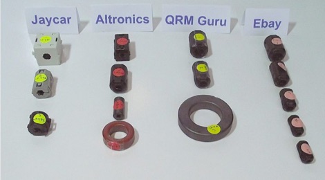 Articles on the correct placement of ferrite noise suppressors are common, but little has been written about the different options and where to buy them. This page contains an interesting comparison of several ferrite types used to reduce RFI.
 -
 This DIY vertical multi-band Windom antenna offers a practical and effective solution for amateur radio enthusiasts seeking a versatile and compact antenna for HF communications. Its simplicity of construction, multi-band capability, and favorable performance make it a valuable addition to any radio shack. The article provides detailed instructions on constructing the antenna and balun, along with diagrams and component specifications. Field tests demonstrated successful contacts with stations across Europe and North America on 14, 18, and 28 MHz. The antenna exhibited comparable performance to a W3DZZ dipole and outperformed a Cobweb antenna on 18 MHz. Low noise levels were observed, effectively suppressing background noise.
 -
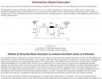 This generator requires 100volts supply at 5mA. A 0 -5 mA meter inserted at J1 measures the crystal current.
 -

-
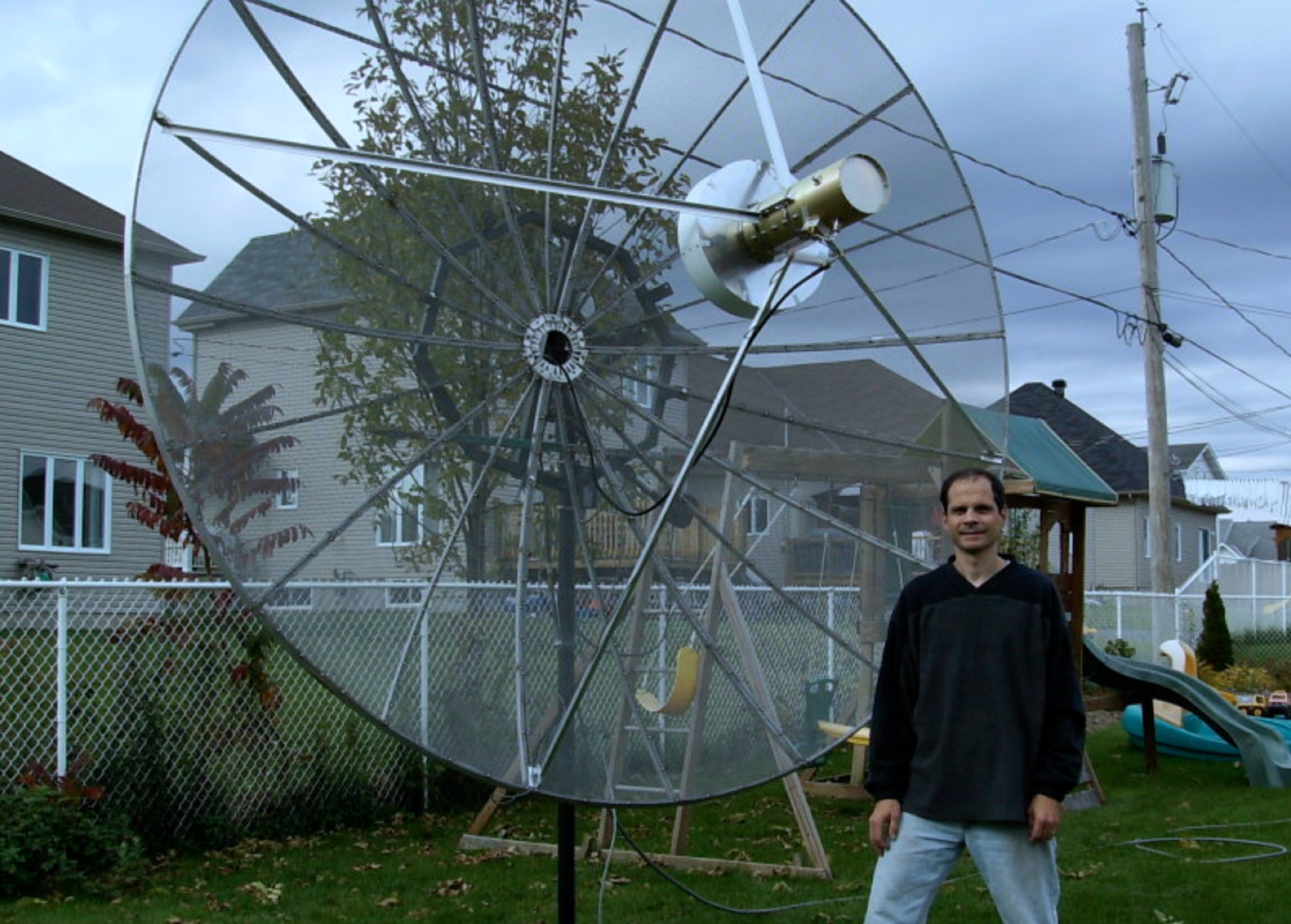 A 3.2m EME dish project that provides a better performance on 1296 MHz (10+dB sun noise vs. 6dB with my 432 array) and an even better performance on 2304 MHz
 -
 Designing and constructing a two-element receiving loop antenna array for HF operation involves specific considerations for achieving high directivity and noise reduction. This resource details a homebrew system comprising two 30-inch diamond-shaped loops, spaced 20 feet apart, which are fed through mast-mounted preamplifiers and passive signal combiners. The operational principle relies on adjusting phase delays between elements via precise _Belden 8241_ coaxial cable lengths, optimized for specific bands from 160m to 20m. Performance data, derived from _EZ-NEC_ modeling, illustrates consistent 90° azimuth-plane beamwidth and low take-off angles across the target bands, with _Receiving Directivity Factor_ (RDF) values comparable to a 300-foot Beverage antenna. The article presents detailed elevation and azimuth plots for 20m, 30m, 40m, 80m, and 160m, demonstrating the array's ability to provide strong response at low DX angles while also supporting _NVIS_ signals. Key components like the _DX Engineering RPA-1_ preamplifier and _DXE RSC-2_ signal combiner are discussed, alongside the importance of impedance matching to preserve antenna patterns. The construction emphasizes self-contained elements that do not require ground radials, offering a compact solution suitable for suburban environments and stealth installations, with a focus on optimizing receive performance independently from transmit antennas.
 -
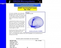 It is very compact, low noise and directive with an impressive 20 to 25 dB front to back
 -
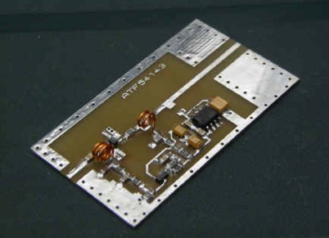 The prototype for this amplifier was originally designed for 70cm and was used on the 2004 3B9C Dx-pedition to Rodriguez Island for satellite and EME. It had a noise figure of 0.49dB with an associated gain of 20dB.