Search results
Query: vertical
Links: 550 | Categories: 26
Categories
- Antennas > 20M > 20 meter Vertical Antennas
- Antennas > 40M > 40 meter Vertical Antennas
- Radio Equipment > HF Vertical Antenna
- Antennas > Vertical
- Manufacturers > Antennas > VHF UHF Microwave > Vertical Antennas
- Manufacturers > Antennas > HF > Vertical Antennas
- Antennas > 160M
- Antennas > 20M
- Antennas > 30M
- Antennas > 40M
- Shopping and Services > Antennas
- Radio Equipment > HF Vertical Antenna > Butternut HF2V
- Antennas > C-Pole
- Radio Equipment > HF Vertical Antenna > Cushcraft R5
- Radio Equipment > HF Vertical Antenna > Cushcraft R7
- Radio Equipment > HF Vertical Antenna > Cushcraft R8
- Antennas > Dipole
- Antennas > Four Square
- Radio Equipment > HF Vertical Antenna > GAP Titan
- Manufacturers > Antennas > HF
- Radio Equipment > HF Vertical Antenna > Hustler 5-BTV
- Radio Equipment > HF Vertical Antenna > Maldol MFB-300
- Antennas > NVIS
- Operating Modes > NVIS
- Propagation > NVIS Propagation
- Radio Equipment > HF Vertical Antenna > Solarcon A-99
-

-
-
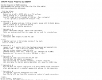
 This VHF 145 MHz antenna is easy to build and with no radials. It shows equal gain of 5/8 lambda. It is light weight, you can hang it somewhere (on a tree may be) and work.
 -
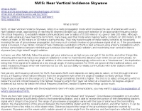
 Theory, Modeling, and Practical Applications By W5JCK, presentation in PDF File. This presentation focuses on Near-Vertical Incidence Skywave (NVIS) antennas, which are crucial for short-range radio communications, particularly in military and emergency contexts. It explores NVIS theory, antenna models, and installation criteria while debunking common myths about reflectors. Key topics include usable frequency bands, optimal installation heights, and the impact of soil quality on performance. The presentation outlines the best bands for daytime and nighttime use, emphasizing the importance of understanding propagation characteristics to enhance communication effectiveness within 200 to 300 miles.
 -
 The Super J Pole antenna is a co-linear vertical consisting of a number of half wave length vertical elements separated with half-wave length stubs (Tuning stub) feed with a folded matching stub by vk6ysf
 -
 The document details the optimization and construction of the _Maria Maluca_ antenna, a compact 6-band (20m-6m) directional beam. It presents a comparative analysis of shortwave antenna principles, highlighting the efficiency gains achieved by using an open feeder line and tuner as a resonant unit, contrasting this with the losses associated with traps or capacitive loads in multiband antennas. The resource specifically revisits an older South American 2-element design for 10, 15, and 20 meters, applying modern NEC-based software to develop a six-band version. Performance data is meticulously tabulated, showing impedance, free space gain, gain at 12m height, elevation angle, and front-to-back (F/B) ratio for each band from 20m through 6m. For instance, on 15m, the antenna achieves 5.1 dBd free space gain and 13.72 dB F/B ratio. The construction section provides practical guidance on element assembly using aluminum pipes and hose clamps, detailing the use of a heavy-duty glass fiber reinforced polyamide rod for electrical separation and bending strength. It also specifies the use of 450-ohm _Wireman_ line CQ 552 for the transmission line. The document includes diagrams for rod fixing, an air-wound balun, and a vertical elevation diagram for the 15m band, illustrating its DX qualification. It also discusses the antenna's suitability for portable and expedition operations, noting its compact transport dimensions (max 1.50m length, 12 lb weight) and quick assembly time (under 15 minutes). The author, Dipl.Ing. Helmut Oeller, DC6NY, is identified as a source for material kits.
 -
 Comparison chart between Cushcraft R8, Hy-Gain AV640 , Butternut HF6V, Gap Titan and Eco 7+
 -
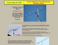 For two purposes a Cross-Yagi can be useful Satellite work or if you need both vertical and horizontal polarization for terrestrial contacts
 -
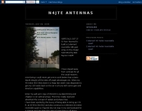
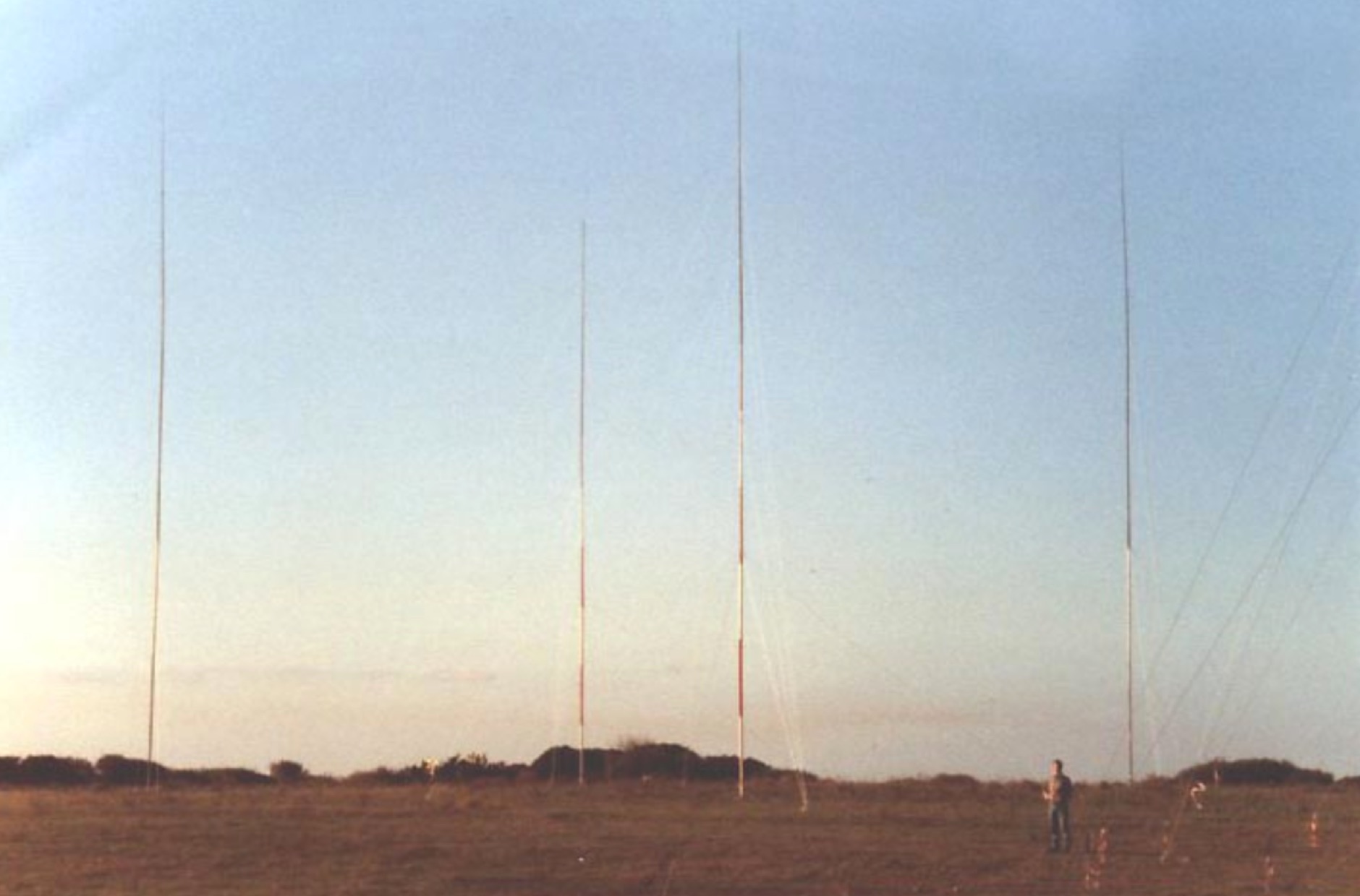 This page is a short description of the four phased verticals system i've build and used. It is primarily intendend to be used on the lower bands 160m, 80m, 40m.
 -
 A portable dualband dipole robust and compact antenna usable for horizontal and vertical polarisation by ON6MU
 -
 A simple drawing of a shortened antenna for 40 meters by using a PVC tube
 -
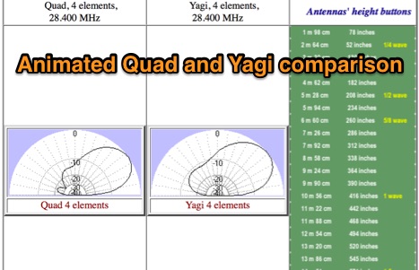 Animated quad and yagi comparison. You can see antennas' characteristics behavior in a vertical plane with changing of the height.
 -
 Article on the HF dual band antenna with construction details and how to add 160 meters to the HF2V
 -
 A 40 ft vertical dipole antenna that can cover HF Bands from 80 to 10 meters winding a dipole in a 12m HD telescoping fiberglass pole
 -
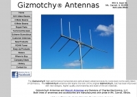 The Charles Gizmotchy high performance horizontal and vertical beam antennas. Two, Six, Ten and eleven meters antennas
 -
 How to make a loading coil for the AD5X portable vertical antenna
 -
 Homebrew a vertical antenna for 40 and 80 meters band based on popular HF2V model by DL7JV
 -
 A quarter-wave vertical antenna design for HF operation offers a practical solution for radio amateurs seeking a compact and efficient multi-band radiator. This project details the construction of a 5-band HF vertical, drawing inspiration from established commercial products such as the _DX COMMANDER_ and the MV6. The design emphasizes ease of assembly and disassembly, making it suitable for portable operations or installations with limited space. The article provides insights into various construction methods and offers practical tips for building a robust yet lightweight antenna. It highlights the benefits of a vertical configuration for DX contacts, particularly on the lower HF bands, and discusses real-world performance observations. The antenna is designed to cover multiple HF bands, providing versatility for various operating scenarios. Operators can achieve significant DX results with this type of antenna, often comparable to more complex arrays, especially when deployed with an effective ground system. The project aims to empower hams to build a capable antenna without significant financial outlay.
 -
 1/2wave vertical antenna for the 6-meterband and a 5/8 ground plane antenna for 50 Mhz
 -
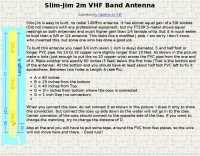
 The page describes the construction of a simple omnidirectional, vertically-polarised dipole antenna for two metres using coaxial cable. It can be used indoors or outdoors, with no extravagant gain claims. The project is low-cost and can be completed in about 20 minutes.
 -
 A vertical antenna for the top band, made with a 26m fiberglass spiderpole by DJ0IP
 -
 Don't buy or build a semi-vertical trap antenna until you read this article! If you can use a drill, saw and screwdriver this is a simple project.
 -
 Homebrew a 2 meter 1/4 wave vertical antenna for the 146 mHz ham radio band
 -
 An homemade portable vertical antenna with a trap near the mid point of the main element. The trap is made with 42mm diameter PVC pipe with 9 turns of wire on it
 -
 Constructing a Lindenblad antenna for 137MHz NOAA satellite reception involves specific design considerations for optimal performance. The resource details the use of 4mm galvanised steel fencing wire, 300-ohm television ribbon cable, and wood/plastic components for the antenna structure. Key dimensions for a 137.58MHz-resonant antenna are provided, derived from the ARRL Satellite Handbook, specifying s, l, w, and d as 42, 926, 893, and 654mm respectively. The antenna is designed for Right Hand Circularly Polarised (RHCP) signals, requiring the four folded dipole elements to be tilted clockwise by 30 degrees. A significant aspect covered is impedance matching between the antenna's 75-ohm impedance and a typical 50-ohm receiver input. A twelfth-wave matching transformer, constructed from 117mm sections of 50-ohm RG-58 and 75-ohm RG-59 coax with a 0.66 velocity factor, is described. The article also addresses coaxial cable and connector selection, recommending 75-ohm Type-N connectors for RG-6 cable in professional setups and F56/F59 connectors for general use, while strongly advising against PL-259/SO-259 connectors for VHF. Strategies for mitigating Radio Frequency Interference (RFI) are discussed, including antenna placement to shield from local TV transmitters and the use of commercial or DIY band-pass filters, such as cavity resonators or helical notch filters, along with ferrite chokes on coaxial cables. Antenna orientation is explored, noting the Lindenblad's 'cone of silence' directly overhead and its maximized sensitivity towards the horizon. An experimental vertical tilt of 90 degrees is presented as a method to improve overhead reception and reduce interference from strong horizontal signals, particularly relevant in high RFI environments like the Siding Spring Observatory site.
 -
 Introduction to NVIS advantages and disvantags.
 -
 G4URH calculations to design your own antennas, ground plane, half wave antennas, Quad Antennas and 5/8 verticals
 -
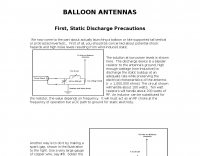 Launching a balloon or kite supported tall vertical or protracted inverted L.
 -
 A vertical antenna for 40 and 80 meters band with no need of antenna tuner, based on a telescopic fiberglass mast of 48 feet by N8NSN
 -
 Experiments with phased wire vertical antennas on 40 meters at VA7ST
 -
 Presents the design and construction of the OK2FJ Bigatas, a portable, automatically tuned vertical antenna covering 80 through 10 meters. It details two distinct control systems: one utilizing BCD band data from Yaesu FT-857/897 transceivers, and another employing voltage level sensing for the Yaesu FT-817. The resource provides specific instructions for building the antenna's radiating element, loading coil with switchable taps, and the control circuitry, emphasizing the use of readily available components. The article outlines the physical construction of the antenna, including the use of duralumin tubes for the radiator and a PVC tube for the coil form. It specifies coil winding details, tap points, and the integration of radial wires for ground plane operation. The control electronics section provides schematics and component lists for both the BCD decoder (using a 74LS42 IC) and the voltage comparator (using an _LM3914_ bargraph driver), enabling rapid, automatic band switching without the minute-long tuning delays common in other systems. Crucially, the antenna achieves rapid band changes, with typical SWR values centered on common operating segments, such as **3.7 MHz** for 80m SSB. It also discusses modifications for CW operation on 80m and the trade-offs between antenna efficiency and full-range automatic tuning on higher HF bands, where manual adjustment of radiator length is suggested for optimal performance on 15m, 12m, and 10m. The resource includes construction photos and a discussion of cable requirements for reliable operation.
 -
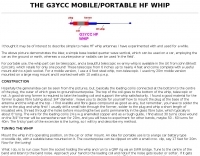 A simple base loaded quarter wave vertical, which can be used on a car or portable by G3YCC
 -
 A vertical half-moxon for the 7 Mhz by F6IRF
 -
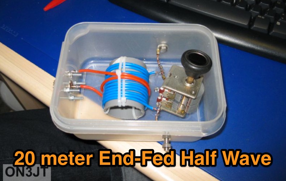
 A quarter wave vertical end-fed antenna for the 40 meters band. As all vertical antennas, also this aerial requires a good earthing system. In this project the ground is composed by twelve 4, wires buried in the lawn by using a spade to create a slit to drop the wire into.
 -
-
 3 Band vertical Marconi-antenna for the bands 40, 80, 160 meters with a ground net of wires as radials.
 -
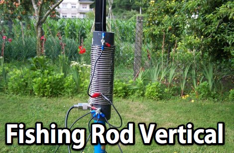 A homebrew fishing-rod vertical using a very nice design from EB5EKT. This antenna works 20, 30, and 40M bands by selecting the tap points using alligator clips
 -

-
 This page shows a homebrew vertical antenna based on the Pac-12 antenna design.
 -
 YF1AR 80 to 40 meter vertical antenna project
 -
 Maldol MFB-300 all band HF vertical antenna review by Steve Nichols
 -
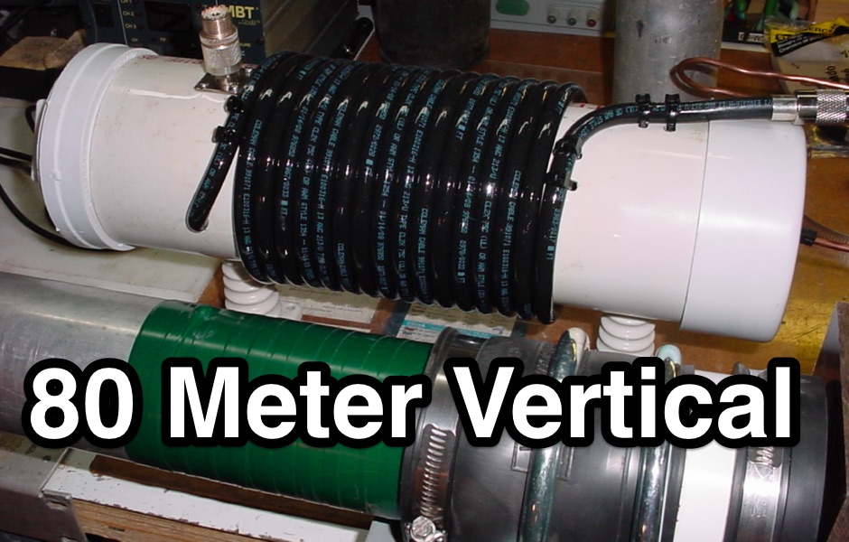 Homebrew a 1/4 wave 80 meter vertical using aluminium tubing
 -
 A 10 Bands mobile antenna for about the price of 2 mobile monobanders.
 -
 A quick vertical for 160 meters portable use
 -
 The St. Louis Vertical Revisited by Dave Gauding, NF0R here are a few ideas and observations on the St. Louis Vertical
 -
 2 element reversible verticals, small footprint, big results.
 -
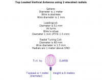 A 3.5 Mhz top loaded vertical antenna built using 2 elevated radials by DJ9RB
 -
 A self supporting vertical antenna for 80 meters by W9OY include pictures and construction details
 -
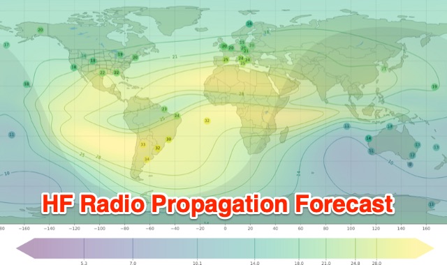 Understanding high-frequency (HF) skywave propagation is crucial for amateur radio operators seeking to optimize long-distance communications. This resource details the fundamental principles of HF radio propagation, including the properties of electromagnetic waves, the characteristics of various HF bands, and distinct propagation modes such as skywave, ground wave, and line-of-sight. It places significant emphasis on the ionosphere's pivotal role in refracting HF waves, explaining how solar activity directly influences ionospheric conditions and, consequently, propagation paths. The resource integrates real-time monitoring capabilities, featuring dynamic charts and data from DX clusters, WSPRnet, and the Reverse Beacon Network, which allow users to track current band activity and propagation conditions globally. It also delves into advanced topics like Near Vertical Incidence Skywave (NVIS) and gray line propagation, providing insights into ionosonde data and various propagation prediction models. The site presents a detailed analysis of solar-terrestrial interactions, geomagnetic indices, and space weather phenomena, illustrating their direct impact on HF communication reliability. Practical tools and applications are highlighted, including real-time QSO planners, online Maximum Usable Frequency (MUF) maps, and alerts for solar flares or geomagnetic storms. The guide systematically breaks down complex concepts into accessible chapters, offering a structured approach to learning about ionospheric regions, diurnal and seasonal effects, and the interpretation of propagation indicators like foF2, MUF, and Lowest Usable Frequency (LUF). This makes it a robust reference for hams aiming to deepen their technical understanding and improve operational effectiveness.
 -
 Multiband and monoband HF Vertical antennas and rotatable dipoles manufacturer based in Texas USA