Search results
Query: wave
Links: 352 | Categories: 55
This query is too generic. Please try adding an additional term to focus your research.
Categories
- Antennas > End-Fed > End Fed Half Wave Antenna
- Operating Modes > Longwave
- Antennas > Longwave
- Manufacturers > Microwave
- Shopping and Services > Microwave
- Operating Modes > Microwave
- Antennas > Microwave
- Shopping and Services > Antennas > Microwave Antenna
- Manufacturers > Antennas > VHF UHF Microwave > Microwave antennas
- Technical Reference > Mircrowave
- Software > Shortwave
- Antennas > Shortwave
- Shortwave Radio
- Manufacturers > Antennas > VHF UHF Microwave
- Technical Reference > Standing Wave Ratio
- DX Resources > Beacons > 10 GHz Beacons
- Antennas > 40M > 40 meter Loop Antennas
- Operating Modes > Aircraft scatter
- Manufacturers > Antennas
- Radio Scanning > Regional > Australia
- Shortwave Radio > BCL Resources
- DX Resources > Beacons
- Shortwave Radio > Beginner's guides
- Shortwave Radio > Broadcasters
- Manufacturers > Broadcasting Equipment
- Shortwave Radio > Clubs
- Manufacturers > Antennas > VHF UHF Microwave > Discone Antennas
- Antennas > End-Fed
- Manufacturers > Antennas > VHF UHF Microwave > Ground Plane Antennas
- Antennas > Horn
-
 BeaconSpot.uk provides an accurate, real-time picture of microwave and VHF/UHF beacons operating across Europe, alongside a worldwide listing of 6-meter beacons. The platform allows users to retrieve detailed data for individual beacons, facilitating in-depth analysis of signal characteristics and propagation paths. Interactive maps visualize beacon distribution by frequency band and display spot coverage for each station, offering a clear geographical overview of active beacons. The system integrates real-time DXCluster spots, sourced from contributors like Alain, ON4KST, and Pascal, F5LEN, and enables users to submit outgoing spots directly to the DXCluster. Beacon keepers can manage their beacon data, receive email alerts upon being spotted, and track their station's ODX (Outstanding DX) records. For every received spot, the distance to the beacon is automatically calculated and displayed, aiding propagation studies.
 -
 137 kHz propagation analysis details ground wave and sky wave mechanisms, drawing heavily from **CCIR Rec. 368-6** for ground wave field strength predictions and **CCIR Rep. 265-7** for sky wave modeling. The resource presents field strength values for 1 W ERP at varying distances, considering ground conductivity and permittivity for ground wave, and ionospheric height (70km daytime, 90km nighttime) for sky wave. Key factors like ionospheric focusing (factor "D"), reflection coefficient ("RC"), and antenna ground pattern factors ("Ft", "Fr") are quantified for 137 kHz, enabling calculation of sky wave field strength. Practical coverage ranges are derived for 137 kHz, showing useful ground wave coverage up to 1600 km over seawater and 1100 km over average ground, assuming a -9 dBuV/m noise floor. Sky wave coverage extends beyond 2200 km during night-time and winter daytime, but is negligible during summer daytime at solar minimum. The document also compares ground wave and sky wave strengths, identifying crossover distances at 550 km (night-time), 750 km (winter daytime), and 1250 km (summer daytime), where interference fading can occur. Adjustments for solar maximum conditions are provided, indicating 2-11 dB higher sky wave values depending on distance and season.
 -
 The SETI League, Inc., founded in 1994, focused on participatory science, developing technology to seek definitive answers to the question of extraterrestrial intelligence. The organization operated in five dozen countries across all seven continents, maintaining the quest for cosmic companions through the efforts of its 1500 members. Although the organization shuttered its virtual doors after thirty years in 2024, the website remains for educational and historical purposes, documenting past research and activities. Key technical resources include the _SETI League Mini-Manual_ for constructing a 12 GHz radio telescope under $200, and software like _SETIFox for Windows_ and _Radio Eyes_ for radio astronomy sky viewing. The site also features _Project Argus_ detections, moonbounce signal detections, and space probe signal detections, providing concrete examples of amateur radio astronomy applications. Publications such as the quarterly newsletter _SearchLites_ and various articles by Dr. SETI (H. Paul Shuch, Ph.D.) are available, alongside information on the Third Penn State SETI Symposium in 2025. The site also offers insights into hydrogen line emission observations, presented in time domain, frequency domain, waterfall, and surface plot formats.
 -
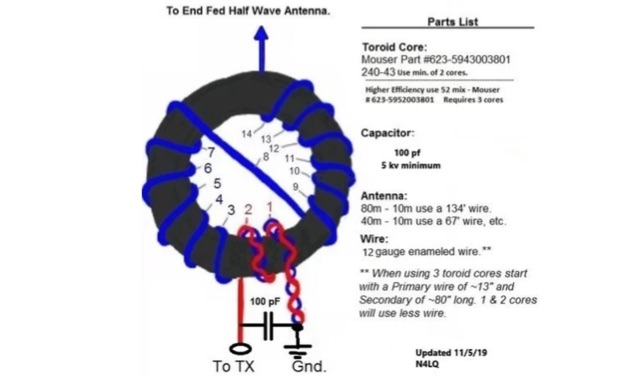 1:49 UNUN using two stacked FT240-43 cores for end fed halfwave antenna. To match the end fed half wave antenna to the coaxial feeder, it is necessary to have a matching network or transmission line transformer.
 -
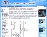 This circuit is very simple and has a fantastic range of potential uses.
 -
 Setting up a ZZ Wave antenna, a dual band loop antenna covering 80 and 40 meters.
 -
 Multi-frequency radio interferometers
 -
 Amplifiers, filters, attenuators, mixers, PLL, switches and frequency dividers, signal generators, power detectors, transimpedance amplifiers, variable gain amplifiers and more
 -
 News, frequency guides and programme information, on shortwave and other international media.
 -
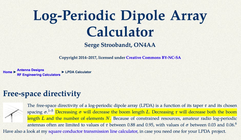 This LPDA calculator is based on the design procedure as described by L. B. Cebik, W4RNL (SK) in the 21st edition of The ARRL Antenna Handbook.
 -
-
-
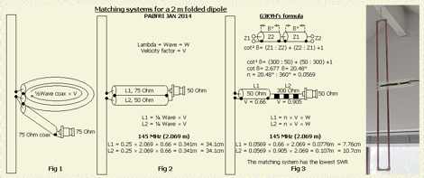 Matching with a half wave or wuarter wave coaxial cable is pretty well known, but an existing 1961 system to do that with two one-twelfth-wavelength transmission lines.
 -
 Demonstrates the complete design and development process for a **Low Noise Microwave Amplifier** (LNA), beginning with conceptual design and progressing through prototyping. The tutorial series covers the initial stages of a single-ended first gain stage, focusing on critical parameters such as noise figure, gain, and stability. It systematically details the theoretical underpinnings and practical considerations for achieving optimal performance in microwave frequency applications. This resource provides a structured approach to LNA construction, enabling radio amateurs and RF engineers to understand the iterative steps involved in realizing high-performance receive-side amplification. It offers insights into component selection, impedance matching networks, and the measurement techniques required to validate design specifications, particularly for **microwave** band operation where noise performance is paramount.
 -
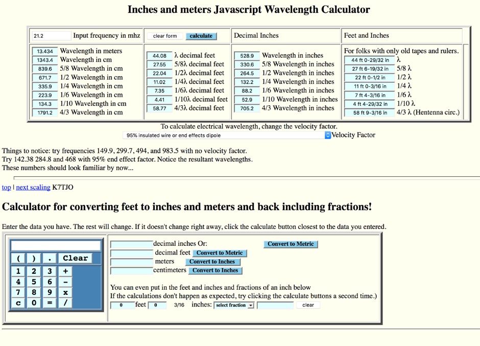 Inches and meters Javascript Wavelength Calculator allow to input a frequency in MHz and calculate wavelenght in several units considering also fractions of wavelenght and the velocity factor. Includes an usefull inch to meter converter
 -
 Summary, tutorial about the basics of what is a waveguide and the basic waveguide theory.
 -
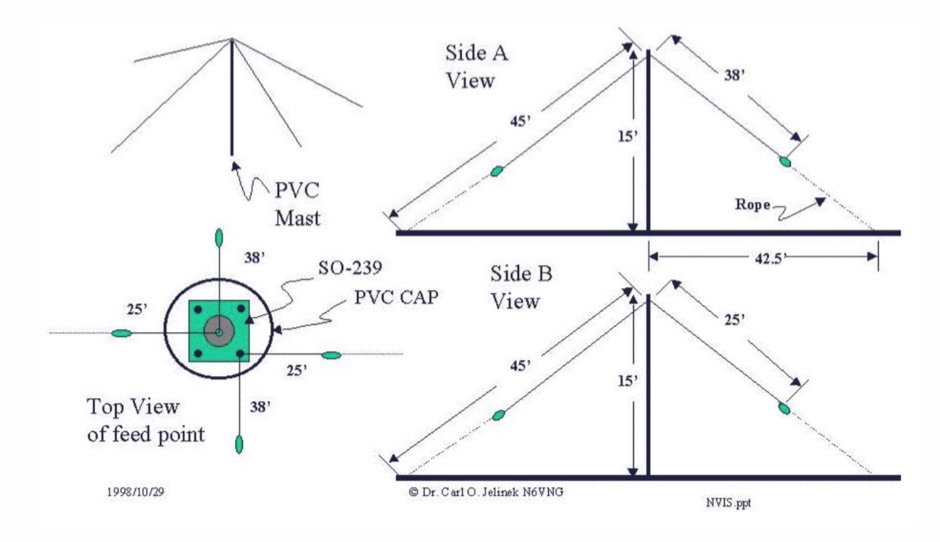 Introduction to NVIS antenna and NVIS propagation. A simple NVIS antenna can be constructed as shown in this article
 -
 Over 20 distinct discussion categories are available on the Amateur Radio Discussion forum, encompassing a wide array of topics relevant to radio enthusiasts in the UK and beyond. The platform facilitates exchanges on technical aspects of amateur radio, including antenna designs, equipment reviews, and operating practices across different bands. Specific sections are dedicated to CB radio and shortwave listening, broadening its appeal beyond licensed amateurs. The forum's structure supports detailed discussions on operational challenges like the "Work All Postcodes" award, which encourages contacts across UK postal districts. Members can track personal statistics, manage contacts, and engage in challenges, fostering community participation and skill development. The resource provides a centralized hub for sharing knowledge and experiences among radio operators, offering practical insights into diverse radio communication facets.
 -
 The Shortwave Radio Audio Archive is a collection of shortwave radio recordings in both the form of a podcast and blog with embedded audio. The collection grows every day and includes both historic and modern day shortwave radio audio recordings
 -
 The DXCC World Map web application is a modern and interactive mapping tool designed for shortwave radio enthusiasts. It showcases a high-quality world map along with the Sun's position, sunrise and sunset times, the terminator, coordinates, QTH locator, azimuth, azimuth map, current DXCC list, Aurora, and WWV Geophysical Alert Messages. Additionally, it provides the SFI, X-Ray, Kp, and Ap indices.
 -
-
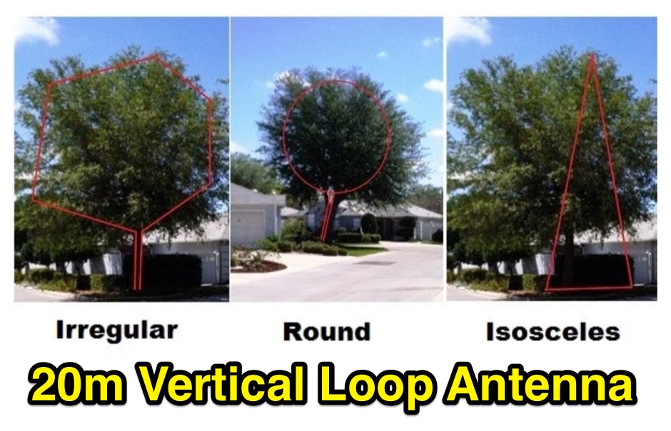 Consider installing a stealth vertical loop antenna if you live in a place with no antenna restrictions. Full wave loop wire antennas allow you to be on the air without installing evidente external aerials.
 -
 Signal generatos, oscillators, direct and indirect synthesizers, exciters custom oscillators
 -
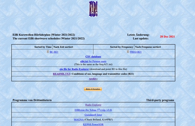 The current EiBi shortwave radio schedules, contains an update aggregated list of radio broadcasting stations schedules. File is provided in text format and is availale to download for free.
 -
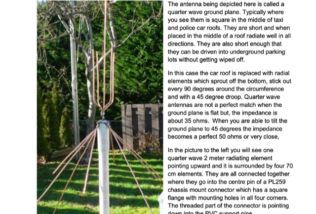 Adapted from a similar project by NA4IT. Made with one quarter wave 2 meter radiating element pointing upward and it is surrounded by four 70 cm elements.
 -
 Supplier of RF, Microwave, & Wireless passive coaxial components, including Coaxial Attenuators, Adapters, Cables, DC Blocks, Terminations, & Connectors
 -
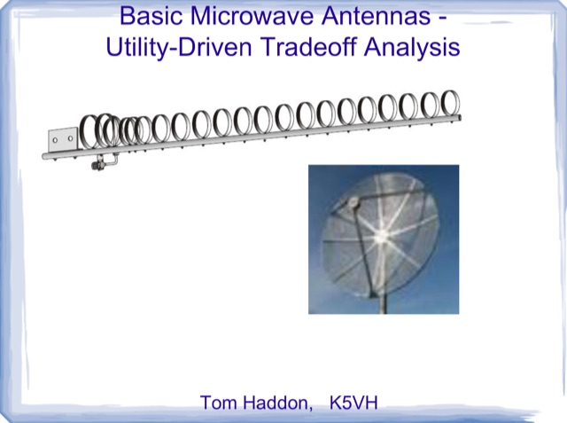 Utility-Driven Tradeoff Analysis, if you want to geto on the microwave bands , you will have to choose the proper antenna for your operating conditions. How to decide is not always easy, and you may also decide to build your own antenna.
 -
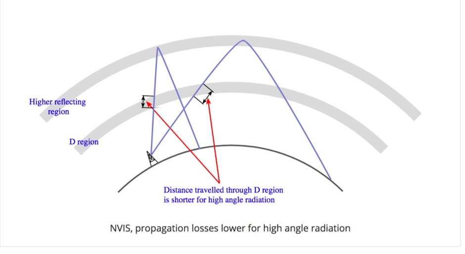 Near Vertical Incidence Skywave propagation is a form of radio wave propagation used on the MF and HF bands to provide radio communications and broadcasting coverage over short distances, especially where the terrain contains obstacles.
 -
 LA6EIA Ole's DX-blog details shortwave listening (SWL) and amateur radio DX operations from Norway, providing insights into propagation conditions and station reception. The blog frequently features specific reception reports, often including details such as frequency, mode, and signal strength, alongside observations of various broadcast and utility stations. It documents the author's personal experiences in chasing DX, offering a practical perspective on radio propagation and equipment performance. The content includes logs of received stations, sometimes accompanied by audio clips or screenshots of waterfall displays, illustrating successful decodes or strong signal captures. This resource presents a chronological record of DX achievements and challenges, reflecting the dynamic nature of radio propagation across different bands and times. The blog distinguishes itself by its focus on real-world SWL and amateur radio DXing from a Nordic QTH, offering a unique regional perspective on global radio phenomena. It serves as a personal journal of radio exploration, highlighting specific callsigns, frequencies, and operational details encountered during DX sessions.
 -
 Dedicated to Promoting Activity, the State of the Art in Equipment Design, and the Exchange of Ideas and Technology for the Amateur Bands Above 902 MHz
 -
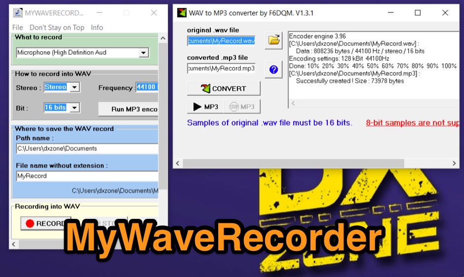 Windows free sound recorder. What you save is what you hear ! Small utility program to capture and save any sound played by your computer. Audio recorded can be converted in MP3 format.
 -
 The _DL4EBY_ resource page provides operational data for Earth-Moon-Earth (EME) communications on VHF, UHF, and microwave bands. It includes a 432 MHz and above EME Directory in ASCII and HTML formats. _K1RQG_ provides 432 MHz and up EME Net Notes. EME Operating Procedures were confirmed at the EME Conference 2002 in Prague. A lunar calendar from _DL7APV_ is linked via _G4CCH_'s pages. Resources for CW contest operation include the _PED411i.zip_ file. A "Cheat Sheet 432 & up" is available for EME operations. The _Dubus_ 70cm CW EME Activity Event is referenced for moonbounce activity. DXZone Focus: Operating Activity | Global | EME, CW | VHF, UHF, Microwave
 -
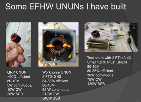 A very well done presentation about End-Fed Half-Wave antennas. This PDF document contains a summary of experiences in how to build custom EFHW antennas. Includes an interesting comparison table of UnUn configurations with recommended toroids, Wire size, turns and capacitors. An useful recap on common errors in building homebrew EFHW Ununs completes the document.
 -
 Operating where independent media is suppressed, _Radio Free Europe/Radio Liberty_ (RFE/RL) delivers news and information in 27 languages to audiences in 23 countries. This resource primarily functions as a news portal, focusing on geopolitical events, regional conflicts, and human rights issues, particularly in areas like Ukraine, Russia, Iran, Afghanistan, and Central Asia. It features articles, videos, podcasts, and photo galleries, covering topics such as international relations, energy politics, and the impact of conflict on civilian populations, often highlighting the perspectives of local journalists and freelancers in challenging environments. The content frequently addresses the operational context of shortwave broadcasting, though the site itself is a digital news platform. For example, it details the implications of long-distance strikes and regional military capabilities, which are relevant to understanding the strategic importance of various communication methods. The resource also provides insights into the challenges faced by populations in areas with limited access to uncensored information, underscoring the role of independent news organizations in providing alternative narratives.
 -

-
 Maintaining vintage Eddystone receivers often presents unique challenges, as detailed by Victor Jenkins in his refurbishment of an EA12, where his deep understanding of RF circuits ensures optimal performance for daily shortwave listening. Similarly, Gerry O’Hara VE7GUH, a prolific contributor to the EUG website and a trustee, meticulously documented his restoration of an Eddystone S830/2, even addressing an unusual instability issue with a follow-up postscript article and YouTube videos demonstrating the fix. His work, along with numerous other articles on the "Restorations" page, showcases a master's approach to bringing vintage sets back to factory specifications or better. Beyond technical restorations, the EUG also shares compelling historical narratives. One such story recounts the discovery of a long-lost 78rpm recording featuring Eddystone Radio Ltd.'s founder, George Stratton Laughton, and other key figures discussing the company's wartime and post-war contributions to shortwave communications. This six-minute BBC production, transcribed into an MP3 file by Peter Carney, offers a rare auditory glimpse into the company's legacy, highlighting its role in supplying equipment to police, ministries, and expatriate British workers. The community aspect thrives through shared experiences, like Roger Trickett's anecdote about his Eddystone EC10, which has been continuously powered for 50 of its 54 years, traveling across continents and enduring various modifications. Another intriguing account from Roy GM4VKI details the "S640 Identity Crisis," where a seemingly standard S640 receiver turned out to be a masterfully engineered 80/20-meter SSB transceiver built into the original chassis by GI3ZX, showcasing incredible ingenuity from a bygone era of amateur radio.
 -
-
 Article on propagation basics. The ground wave used for radio communications signal propagation on the long, and medium wave bands for local radio communications
 -
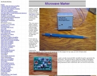
-
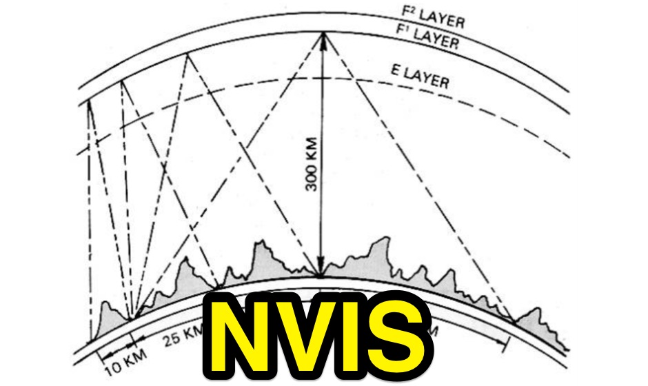 Operating NVIS mode, understanding operation frequencies, choosing the proper antenna to operate with the Near Vertical Incidence Skywave propagation
 -
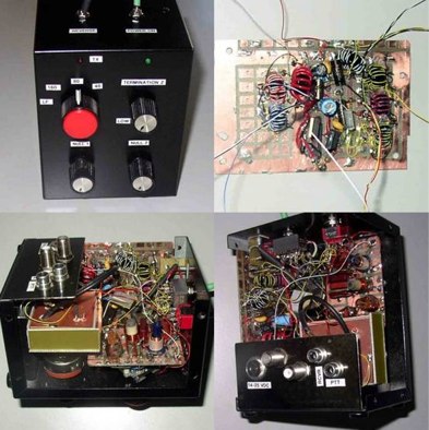 Making the Short dual wire Beverage better by Jeff Smith VE1ZAC
 -
 OH3TR operates the OH3SHF microwave beacons on 2.3, 3.4, 5.7, 10 and 24 GHz
 -
 Operating in the **microwave** spectrum, Response Microwave, Inc. specializes in the design and manufacturing of RF and microwave signal processing components and subsystems. The company's product line encompasses a wide array of offerings, including Connectivity Series components, rotary joints, phase shifters, cable assemblies, surge protectors, terminations, Hybridline/Couperline products, circulators/isolators, directional couplers, quadrature hybrids, attenuators, custom assemblies, filters/diplexers, DC blocks & bias tees, power dividers/combiners, laser diodes & drivers, high-frequency connectors, and precision test accessories. This extensive catalog supports various applications requiring precise signal manipulation and transmission at elevated frequencies. The resource provides access to a comprehensive product catalog and a dedicated connector catalog, detailing specifications for components like **high-frequency connectors** and test cables. While specific performance data or comparative analyses are not directly presented on the main page, the breadth of products indicates a focus on providing foundational building blocks for microwave systems. The company emphasizes customer service and aims to be a reliable source for RF/Microwave/Optics product requirements, serving a growing customer base with its specialized component offerings.
 -
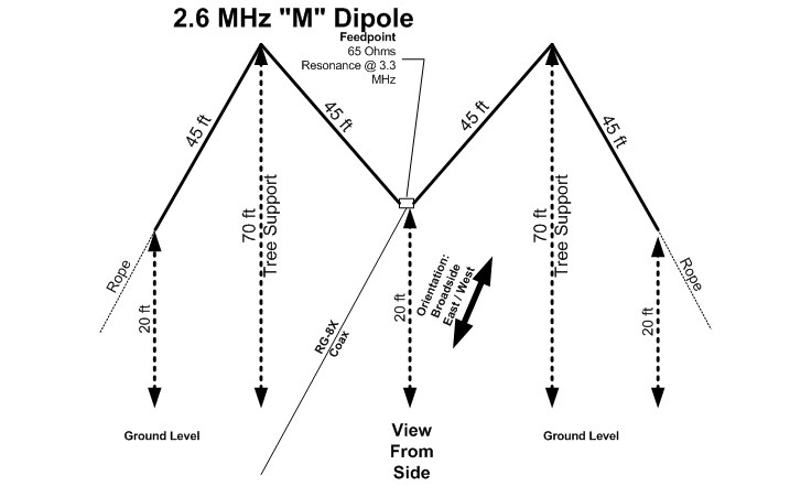 The 2.6 Mhz M Dipole is constructed from #10 stranded insulated wire available in most hardware stores. The feedpoint uses a T-section of PVC pipe
 -
 RSGB article for beginners. How to build a dipole antenna, construction tips and correct setup of inverted-ve dipole antennas
 -
 Constructing an End-Fed Half-Wave (EFHW) antenna offers a practical solution for HF operators seeking a multiband wire antenna without the need for extensive radial systems. This design typically employs a high-impedance transformer at the feed point, matching the antenna's inherent high impedance to a 50-ohm coaxial feedline. The article specifically details a 2012 approach, focusing on a transformer with a 49:1 turns ratio, which is a common configuration for EFHW antennas. The resource outlines the construction of a wire element cut for a half-wavelength on the lowest desired band, with specific coil arrangements enabling operation on harmonically related bands such as 40m, 20m, and 10m. It discusses the physical dimensions and winding details for the matching transformer, often utilizing a ferrite toroid core to achieve the necessary impedance transformation. The content provides insights into the operational principles and practical considerations for deploying such an antenna, including methods for tuning and optimizing performance across multiple amateur radio bands. While acknowledging that the presented information from 2012 may be superseded by newer insights, it serves as a foundational reference for understanding EFHW antenna theory and construction.
 -
 MegaWave Corporation's goal is to provide services and products of the highest quality to its many customers in the areas of antenna design and development, and radiowave propagation.
 -
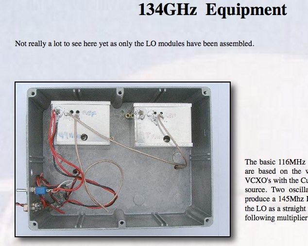 Developing operational amateur radio equipment for the 134 GHz band presents significant technical challenges, particularly in frequency generation and stability. This resource details the construction of a 134 GHz system, outlining its architecture with separate transmit (Tx) and receive (Rx) modules, each employing a local oscillator (LO) and RF head units. The system utilizes a dual Flann 50 GHz lens-type horn antenna configuration for optimal signal coupling. The transmit path incorporates an LMX2541 synthesizer chip operating at approximately 2.8 GHz, referenced by a 10 MHz double-oven Morion OCXO for exceptional stability. This signal is multiplied through a series of stages (X4, then X2) to generate a 22.4 GHz signal, which subsequently drives a dual series diode multiplier to produce the final X6 signal for 134 GHz operation. The receive side features an anti-parallel diode mixer coupled to a 144 MHz transceiver via a preamplifier, ensuring effective downconversion. Operational mode is CW, achieved by keying a multiplier stage. The project includes images of the Tx and Rx head units and describes a successful 3.5 km test with G8ACE, demonstrating stable signal tones due to PLLs locked to OCXOs at both ends, confirming the system's robust performance.
 -
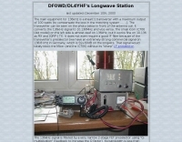 DF0WD DL4YHF Longwave Station include a linear transverter and antenna tuner
 -
 Presented is a historical collection of short-wave listening (SWL) QSL cards, primarily from the late 1930s and early 1940s, offering a glimpse into early international broadcasting and the technical pursuits of SWL operators like Les Miles during that era. The resource showcases specific QSLs from stations such as _Broadcasting Corporation of Japan_, _XGOY - The Central Broadcasting Administration_ in Chungking, China, and _Australian broadcasting ship, Kanimbla VK9MI_, each with reception dates and frequencies like 11.90MHz or 9.525MHz. It highlights the self-sufficiency of SWL enthusiasts who constructed and maintained their own radio and test equipment, evoking the sensory experience of vintage valve receivers. The collection provides concrete examples of international broadcast stations active before and during World War II, including _2RO3 - Rome_ and _WRUL - World Wide Broadcasting Foundation_ from Boston. Each QSL entry details the station, location, reception date, and often the frequency, such as 9.63MHz or 11.26MHz, allowing for historical verification of broadcast schedules. The resource also briefly mentions the operational details of the _VK9MI_ offshore radio station, directing readers to further information on its history. This compilation serves as a tangible record of global radio communication during a pivotal historical period.