Search results
Query: 40 Meters
Links: 324 | Categories: 2
-
 Presents a historical timeline of amateur radio satellites, beginning with the inaugural _OSCAR 1_ in 1961 and extending through ARISSat-1 in 2011. It outlines the evolution of these orbiting transponders, initially simple battery-operated beacons, into sophisticated platforms supporting educational initiatives, emergency communications, and technology demonstrations. The document highlights the significant contributions of various AMSAT organizations and other entities in developing and deploying these spacecraft. Each entry provides specific launch details, including the date, launch vehicle, and initial orbital parameters such as apogee, perigee, and inclination. For instance, AMSAT-OSCAR 7 (AO-7) launched in 1974 into a 1459.00 x 1440.00 Km orbit, while AMSAT-OSCAR 40 (AO-40) achieved a highly elliptical 58665.00 x 1157.00 Km orbit. The resource also notes the allocated amateur satellite service frequencies, including 29 MHz (10m), 145 MHz (2m), 435 MHz (70cm), 1270 MHz (24cm), and 2400 MHz (13cm). The compilation serves as a concise reference for understanding the progression of amateur satellite technology and operations over five decades, showcasing the collaborative efforts of the global amateur radio community in space communication endeavors. It details the physical characteristics and project affiliations for many of the **20** satellites listed, providing a foundational historical context.
 -
 No exotic claims are made for this antenna. Author just tried a few WSPR experiments on 40 meters and was surprised with the results. What appears below may inspire you to try something equally off-the-wall, to see what happens.
 -
 Learn Morse Online in 40 lessons with this web based morse code learning program, based on the Koch method. Choose the lesson, adjust the wanted parameters, and start the transmission of a set of random characters based on chosen lesson. Recognize the code and verify it at the end of the lesson.
 -
 An home made remote antenna tuner project that with a 6 meter random wire and two radials of about the same length, can tune from 40 to 10 meters without any issue.
 -
 A loop antenna for 80 and 40 meters band, the main loop is based by a crossed line using aluminium strip lines. The main loop diameter is 150 cm.
 -
 This antenna is an off-center fed spiral dipole for 40 meters. The spiral dipole is very compact, making it well-suited for limited space (like an apartment patio), while the off-center feed gives the antenna some multiband capability.
 -
 A fand dipole antenna home made for the 7,14,50 MHz. This article descbribes how to homebrew the antenna, hot to setup and some SWR measurements.
 -
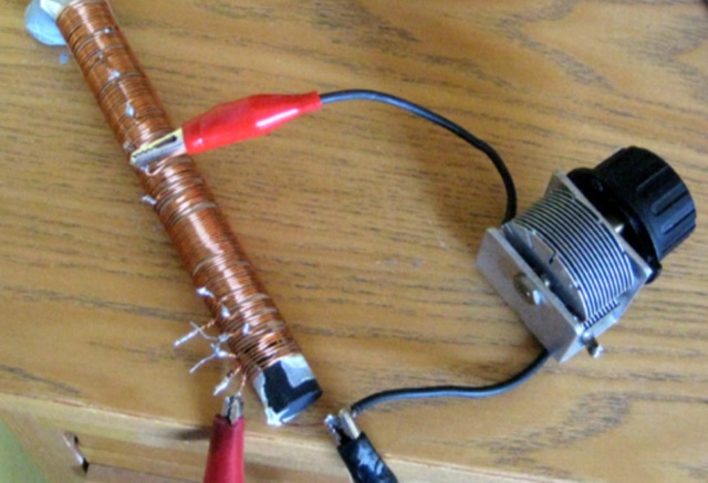
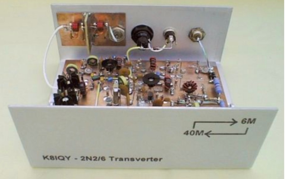 This project is a 40 meter to 6 meter CW "no tune" transverter using ten 2N2222 transistors and one 2N2907. The transverter requires 2 watts of drive from a 40 meter cw transceiver and outputs 2 watts on 6 meters.
 -
 A simple portable dipole antenna for the 40 meter band using a total lenght of 18 meter. It can be used for 80 to 10 meters coverage using a antenna tuner.
 -
 A 0-30 MHz step attenuator, constructed from switchable Pi attenuation pads, provides a practical tool for evaluating receiver sensitivity and calibrating S-meters. The design utilizes readily available 5% tolerance resistors, with values derived from paralleled components to achieve specific attenuation steps. A schematic (Fig 1) illustrates the circuit, including PCB pad shielding, while a table details required and actual resistor values, along with percentage differences. Measurements of voltage input versus output at various frequencies are used to calculate dB attenuation, presented in a graph (Fig 4). The resource includes formulas for determining output voltage from a known input and a comprehensive 0-40 dB voltage multiplier table, which is crucial for precise signal level management. The project also references external attenuator calculators and equations for further study. Photos (1-3) provide visual guidance for the assembled unit, showing bottom, top, and front views. The project emphasizes the use of **Pi attenuation pads** and **receiver sensitivity** evaluation, offering a hands-on approach to RF signal management.
 -
 A portable home made wire dipole antenna that works on 40 30 and 17 meters band.
 -
 The PG7V Contest Calendar provides a curated listing of significant **HF contests**, with a particular focus on events relevant to European amateur radio operators. It details contest specifics such as start and end times in UTC, eligible bands (e.g., 80 meters, 40 meters, 10 meters), and required exchange information (e.g., serial number, CQ-zone, DOK, locator, age). The calendar includes diverse modes like CW, SSB, PSK63, RTTY, and FT4, catering to various operating preferences. Featured contests include the RSGB 80m Club Championship, WW WPX Contest, IARU Region 1 Fieldday, and ARRL International Digital Contest. Each entry links directly to the official contest rules for detailed information. The calendar also notes specific participation rules, such as the 1 KHz QSY requirement in the HA3NS Memorial Contest or the 24-hour single-operator time limit in the ARRL International Digital Contest. This resource is updated regularly, ensuring timely information for upcoming **contest operations** over a four-week period. It serves as a practical tool for hams planning their contest activity.
 -
 Low-frequency (LF) radio time signals, operating primarily in the 40–80 kHz range, are broadcast by national physics laboratories for precise clock synchronization. Transmitters like **JJY** (40 kHz, 50 kW; 60 kHz, 50 kW), RTZ (50 kHz, 10 kW ERP), MSF (60 kHz, 15 kW ERP), WWVB (60 kHz, 50 kW ERP), RBU (66.66 kHz, 10 kW), and DCF77 (77.5 kHz, 50 kW) cover vast geographic areas, often several hundred to thousands of kilometers. LF signals offer distinct propagation advantages over higher-band transmissions such as GPS. Their long wavelengths (3–6 km) enable effective diffraction around obstacles like mountains and buildings. The ionosphere and ground act as a waveguide, eliminating the need for line-of-sight and allowing a single powerful station to cover extensive regions. Ground wave propagation minimizes ionospheric variability effects on transmission delay, and signals penetrate most building walls effectively. Robust and low-cost receivers, often priced at 20–30 USD/EUR, are widely used in radio clocks. These receivers typically comprise a tuned ferrite core antenna, a receiver IC (e.g., Atmel T4227, U4223B, MAS1016) for amplification and AM detection, and a microcontroller for decoding the time signal and phase-locking a local clock. Specific components for DCF77, MSF, and WWVB are readily available from vendors like HKW Elektronik and Ultralink.
 -
 A portable operation experience with a SpiderBeam pole during a contest, testing wire antennas, like dipole and delta loops configurations on 20 40 and 80 meters band.
 -
 The Buddistick antenna, as demonstrated by KP4MD, effectively handles up to **250 watts** and provides coverage from 40 through 10 meters, with an optional coil extending operation to 80 and 60 meters. KP4MD's video presentation meticulously describes the antenna setup, emphasizing the critical role of the _shunting coil_ for achieving resonance on lower bands like 40 and 80 meters. This practical approach highlights how a compact antenna can deliver solid performance from a constrained location. SWR curve diagrams are included, clearly illustrating the impact of the shunting coil on the antenna's resonating frequency. These visual aids provide concrete evidence of the adjustments needed for optimal operation across different bands, particularly when space is at a premium. KP4MD's insights are particularly valuable for hams operating from apartments or other limited spaces, showcasing real-world results from a balcony installation.
 -
 This page describes a comparison study on seven different beam antennas for 40 meters band. Yagi antennas, moxon antennas, mini horse all antennas are described with schema diagram , azimuth plot and SWR F/B Gain diagram
 -
 Basic magnetic loop antenna examples and loop aerials theory explained. This article inclued some interesting tricks on building magnetic loop antennas and an usefull excell sheet to help compute magneti loop antennas calculating power efficiency from 10 to 40 meters band
 -
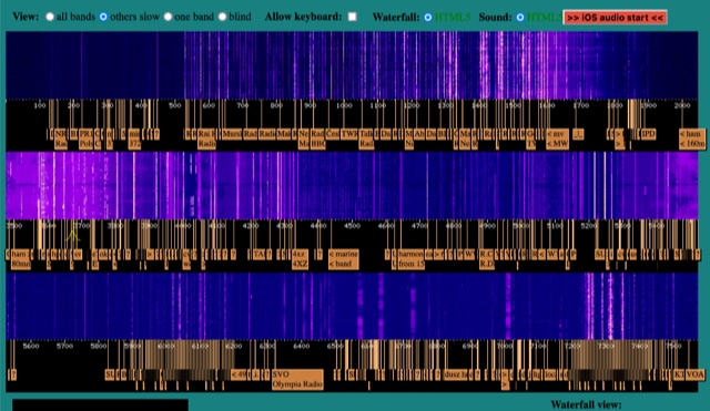 WebSDR receiver located near Krizevci, Croatia with 0-2 MHz, 60-80 meters band and 40-49 meters band
 -
 An 20 30 40 meters trapped dipole antenna plan for sota and portable operations.
 -
 A quarter wave vertical omni-directional antenna for 7 MHz. Formulas for dimensions in feet and meters are provided. Ideal radial angle is between 35° and 45°. Velocity factor (Vf) varies based on coax type.
 -
 Basically, this antenna is a 23-foot wire fed through a 4:1 un-un transformer. This antenna can be easily used in portable operation, for operating all bands from 40-10 meters.
 -
 The ARRL's End-Fed Half-Wave (EFHW) Antenna Kit is an easy-to-build four-band antenna designed for 10, 15, 20, and 40 meters. Ideal for portable operations, it includes a 49:1 impedance transformer for compatibility with most transceivers. This project, detailed with step-by-step assembly instructions, involves creating a weatherproof enclosure and impedance matching network. The kit simplifies HF operations and supports multiple configurations, making it a versatile tool for amateur radio opertors.
 -
 This page describes an entirely simple, One-Knob matchbox that will match this antenna efficiently on 40, 30 and 20m, using a simple circuit that can be switched between series-resonant and parallel-resonant with just one banana jumper
 -
 Clarifies the intricate process of calibrating the _Elecraft K2_ dial, addressing common user challenges and lively discussions on the Elecraft reflector. Wilhelm, W3FPR, dissects the K2's PLL synthesizer design, chosen for its low phase noise, kit-friendly duplication, and cost-effective components. The resource emphasizes the critical role of the 4000.000 kHz reference oscillator's accuracy during CAL PLL, CAL FIL, and CAL FCTR functions, noting its dependence on temperature and crystal stability for optimal performance. Explaining the K2's frequency display, the document reveals it relies on microprocessor-driven look-up tables generated by CAL PLL for VFO values and CAL FIL for BFO values. In SSB and RTTY, these combine, while CW and CWr modes also factor in the sidetone pitch. The author details inherent limitations, such as the 10 Hz increment resolution of the dial and varying PLL step sizes—from 3 Hz on 160 meters to 10 Hz on 10 meters. BFO increments range from 20 to 35 Hz, collectively limiting practical dial accuracy to within **20 Hz** with diligent effort, or **30 Hz** for a slightly less demanding task. The guide outlines a four-step calibration procedure: setting the reference oscillator, running CAL PLL, running CAL FIL, and setting all BFOs. It highlights the _N6KR Method_ as a particularly easy and accurate approach, requiring only the K2 and a known frequency source like WWV for zero-beating, eliminating the need for external test equipment.
 -
 This type of antenna is a popular antenna design as the performance is very good across the HF bands and requires little or no tuning. It’s a dipole fed off center with a 4:1 balun at the offset feed point. The antenna shown covers 80, 40, 20 and 10 meters. The formula can also be used to adjust the overall length to cover more or fewer bands and the resulting overall length. 160-10m, 80-10m or 40-10 meters depending on your available space. Other bands will require a tuner.
 -
 Constructing a dual-band antenna for 40 and 20 meters often involves compromises in size or complexity. This resource presents a compact _open sleeve dipole_ design that addresses these challenges by using 450-ohm ladder line and folded elements to achieve a total length of approximately **17.17 meters**, significantly shorter than a full-size 40-meter dipole. The design leverages electromagnetic coupling, where a primary radiator handles the 40-meter band, and a second conductor resonates on 20 meters without direct electrical connection. This configuration eliminates the need for traditional traps, loading coils, or switching components, simplifying construction and reducing potential loss points. The antenna is fed with RG-58C/U coaxial cable, and a common-mode choke is recommended at the feed point to suppress sheath currents, ensuring a cleaner radiation pattern and minimizing RF in the shack. The design is well-suited for portable operations, field deployments, temporary installations, and restricted urban environments where space is a premium, offering solid performance on both HF bands.
 -
 WebSDR Pardinho SP Brazil providing access to HF bands 160 80 40 20 15 11 meters bands.
 -
 A 60-foot available space, for example, might necessitate a shortened multiband dipole array to cover 80, 40, and 15 meters effectively. This resource details the construction of such an antenna, combining full-size and coil-loaded dipoles on a single feedline. It addresses the common challenge of fitting multiple HF bands into restricted physical footprints, providing practical guidance for hams with smaller backyards or portable operations. The core of the offering is an interactive calculator that determines required loading coil inductance and dipole lengths for various amateur bands from 160m to 10m. Users input their available space, and the tool provides dimensions, coil turns, and an efficiency rating (Good or Fair) based on the antenna's electrical length relative to a quarter-wavelength. It also suggests suitable _PVC_ pipe diameters for coil forms. The article further illustrates a center feed-point assembly using an 18-inch section of 2-inch _PVC_ pipe, detailing eye-bolt spacing and coaxial connector installation. It emphasizes the importance of adequate spacing between parallel dipoles and offers customization options for the feed-point, including the addition of a _Balun_ for improved feedline isolation.
 -
 A review of the SteppIR UrbanBeam antenna a two element Yagi antenna working 40-6 meters. The UrbanBeam is a good choice for those thare are limited by lot size, regulations, city regulations.
 -
 A W8JK/Moxon antenna variant with 400cm long monopoles is detailed, demonstrating a **1dbd** gain improvement over the traditional Open-Folded W8JK. This design, relying on the _Moxon principle_, achieves higher radiation impedance, leading to increased antenna efficiency and reduced losses. The article includes VNA output data for various HF bands, showing impedance characteristics from 10.1 MHz to 50.1 MHz, and provides NEC model wire definitions for the antenna structure. Field tests performed by F6IIV, Marc, compared his W8JK Moxon style antenna against a Cobweb antenna at the same height. Results indicated the W8JK Moxon variant provided a **6dB** (1 S-meter point) advantage on most bands from 20m to 10m, and a significant 10dB (1.5 S-meter points) advantage on 15m. The antenna features a 2.70m boom and a turning radius of less than 3 meters, making it suitable for limited space installations while maintaining bi-directional performance on most bands.
 -
 Palau T8GM (OC009) September 6-7 and 15-19 This is solo DXpedition and CW only. Station will be Elecraft K3 and ECO R7+ vertical for 40-10 meters.
 -
 A dedicaed vertical antenna for 80 meters band based on a 40 meter vertical experiment
 -
 With this antenna the coverage is 80,40,20,15 and 10 meter band without any antenna tuner and the average SWR is below 1.2 on phone bands. The total antenna lenght is about 23 meters , with one 20.4 meters long segment from the 1:49 transformer to the 110uh coil and about 2.2 meters long segment from the coil to the insulator.
 -
 DL7JV shares his practical experience building and testing capacitive antennas, initially skeptical of their performance compared to magnetic loops and mono-band dipoles. His interest was piqued after hearing a Spanish station running 100 Watts on 80 meters with a 1-meter Micro Vert, making DX contacts into PY and UA0, despite the antenna being only 4 meters high in a garden. This prompted DL7JV to investigate further, consulting resources from DL7PE and DL7AHW, the latter providing DOS programs like "Mitspule.exe" and "Spulenprg.zip" for calculating antenna dimensions and coil conversions. The article outlines the construction of two prototype antennas: one for 7.050 MHz using a 75mm PVC pipe and another for 3.550 MHz with a 110mm PVC pipe. Both designs feature aluminum foil condensers and coils wound from 1mm² H07V-K wire. DL7JV provides specific measurements for the condenser capacitance, surface area, diameter, height, coil inductance, turns, and wire length for both 40m and 80m versions, along with RG58 feedline lengths. Initial reception tests for the 7 MHz antenna, placed indoors, yielded impressive S9+5 signals from a German station compared to an S8 from a 42-meter roof-mounted loop, even hearing a Japanese station. Transmission attempts on April 4, 2004, despite moderate solar storm conditions, resulted in successful QSOs on 7 MHz with EA5OT (579/559) and on 3.5 MHz with YT1NT (579/559) and G4KKI (579/559) using 100 Watts. DL7JV notes the antenna's sensitivity to coordination and feedline layout, suggesting a modification from DL7AXO involving a 500pF fixed capacitor and coil tap for improved SWR stability. He concludes that while the capacitive antenna is space-saving and performs well for reception and 100W transmission indoors, its transmit performance doesn't yet match larger antennas, with further outdoor field tests planned. DL7JV also intends to build a 1.8 MHz version.
 -
 Vertical end fed antenna used for portable operations. The antenna will work on 80 with acceptable results, it will work fine on 40m, and it will be a good deal better than a normal 1/4 wave GP on 20, 17, 15 meters.
 -
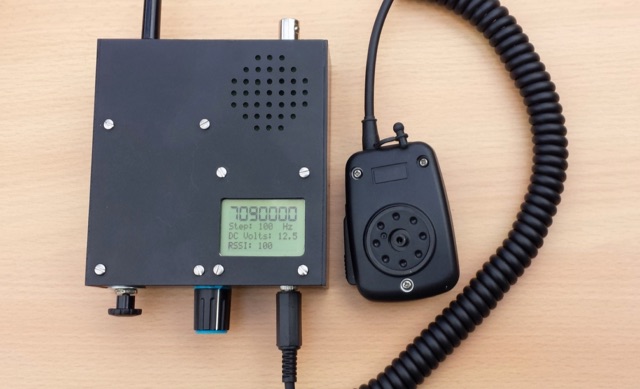 A home made portable QRP transceiver designed to work on 40 or 80 meters SSB band.
 -
 The longest element has a total length of 14m and has a boom length of 5.5 meters featuring a total bandwith of 166 kHz
 -
 Building an End-Fed Half-Wave (EFHW) antenna from a kit, as detailed by Frank Bontenbal, PA2DKW, with process photos by Bob Inderbitzen, NQ1R, offers a practical approach for hams. This specific kit, a collaboration between ARRL and HF Kits, targets 10, 15, 20, and 40 meters, making it a versatile option for HF operations. Unlike a center-fed dipole, the EFHW is a half-wavelength antenna fed at one end, which simplifies deployment, particularly for portable use. The construction guide meticulously outlines the assembly of the 49:1 impedance matching network, crucial for transforming the antenna's high impedance (around 2,500 Ohms) to a transceiver-friendly 50 Ohms. Steps include preparing the enclosure by drilling holes for the coaxial connector and antenna connections, followed by the precise winding of enameled copper wire onto a toroid to create the transformer. The guide emphasizes careful insulation removal and soldering for reliable connections. Final assembly involves integrating a 100 pF capacitor for higher band compensation, soldering the transformer's primary and secondary sides, and conducting SWR tests with a 2K7 resistor or a half-wavelength wire. The document also provides examples of wire lengths for different bands, such as 16 feet for 10 meters or 66 feet for 40 meters, demonstrating the transformer's adaptability for various half-wavelength configurations.
 -
 Experimentin wire antennas on top band using several type of aerials. This includes a 40 to 160 meters EndFed Half Wave kite antennas and 160m/80m loaded vertical antenna.
 -
 This article documents the author's journey in building, modifying, and testing a DIY short vertical antenna for 40, 30, and 20 meters, with potential 80m capability. Initially inspired by Parks On The Air (POTA), the author explores pedestrian mobile operation and details various experiments to enhance antenna performance. The piece highlights challenges, SWR tuning, portability, and practical results, emphasizing a balance between efficiency and size. Ultimately, it showcases the adaptability of DIY antennas for portable ham radio applications.
 -
 This article introduces an Arduino-based QRP CW Transceiver designed for lower HF bands. The journey begins with the Wotduino, evolving from a keyer to a multi-mode beacon. The development includes a QRP transmitter and culminates in a receiver inspired by Roy Lewallen design. The transceiver, controlled through a control bus features a signal path, modulation, filtering, and adjustable frequency settings. Despite initial testing intentions, successful QSOs on 80 and 40 meters showcase its functional capabilities.
 -
 Make your own dipole for 40 and 80 meters band, assembling standard product parts like 40 meter traps, the 1:1 balun and insulators
 -
 The DK7ZB-Dualband-Moxon-Beam provides a compact, high-performance antenna solution for 28 MHz and 50 MHz operations, utilizing a single 50-ohm feedpoint. This design functions as a mini-beam on 10 meters, achieving a gain of **4.0 dBd** with a front-to-back ratio of _30 dB_, while operating as a 2-element Yagi on 6 meters, yielding a gain of **4.3 dBd** and an 11 dB F/B ratio. The antenna's dimensions are approximately two-thirds that of a full-size 10-meter beam, making it suitable for smaller spaces. Construction details include a parts list specifying aluminum tubes of various diameters and lengths for the reflector and radiator elements. Builders like Aleks (S54S) and Marcio (PY2OK) have successfully replicated the design, with Aleks noting the utility of bending corners during assembly. Fine-tuning is accomplished by adjusting the length of specific elements that slide into larger tubes. The feeding system incorporates a balun, with options for either 300 watts using RG188 on an FT140-43 core or 1 kilowatt using _Aircell-5_ on an FT240-43 core, ensuring versatility for different power levels.
 -
 Build A Shortened 40 Meter Vertical antenna For POTA / SOTA Activations. A project for a portable wire antenna for 40 meters band suitable for POTA or SOTA operations.
 -
 This antenna is designed for 40, 80 and 160 meters to complement a tri-band beam normally taken on DX peditions for 10, 15 and 20 meters, so six bands can be worked with only two antennas.
 -
 Original HF magnetic loop antenna designed by the author to work in conjunction with QRP transceivers like the FT-817 in portable operations. In this configuration the loop can operate from 30 to 10 meters. Using a two spires radiator of the same diameter it also covers 40 meters.
 -
 WB8LZR details the construction and initial field results of a multi-band vertical wire antenna, designed to complement his existing horizontal loop for improved DX on 80 meters. The antenna utilizes a 67-foot vertical wire, configured as a quarter-wave radiator on 80m, and employs a 1:1 current balun for RF isolation on 80m, 30m, and 17m. For bands like 40m, 20m, and 10m, where the wire acts as a half-wave or full-wave radiator, an additional impedance transforming _unun_ is integrated to manage the significantly higher feedpoint impedance and voltage. The author notes the vertical's performance as a receiving antenna, observing reduced noise compared to his main horizontal loop, particularly on 80m, and even hearing some long-path signals the loop missed. Initial QRP contacts, including a **1-watt** QSO with a _VP2 station_ on 30m, demonstrate its transmit capability. While the radial system is currently rudimentary, the project outlines practical considerations for multi-band vertical deployment and impedance matching.
 -
 Four distinct amateur radio bands, specifically 40, 30, 20, and 15 meters, are addressed by a portable dipole antenna design. This antenna utilizes a manual switching mechanism, employing "fast-on" or flying connectors to change bands. The design is presented with an animated plan, illustrating how operators can adjust the operating frequency by opening and closing specific connections on the antenna elements. The resource describes a _4 savos dipol_ (4-band dipole) that can be shortened for specific band operation. It provides practical information for hams seeking to construct a versatile, multi-band wire antenna for portable operations or fixed station use. This design offers a straightforward approach to achieving multi-band HF capability without complex tuning units, making it suitable for field deployments like SOTA or POTA activations where rapid band changes are beneficial.
 -
 A CW contest running every Monday, from 1630 UTC to 1729 UTC on 40 and 80 meters band
 -
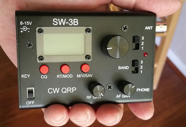 The SW-3B is a Three-band CW QRP transceiver, Weight 180g, output power 5W at 12v, 2W at 9v, works on 40 30 and 20 meters band