Search results
Query: ion
Links: 2266 | Categories: 701
This query is too generic. Please try adding an additional term to focus your research.
Categories
- DX Resources > DX Peditions > 2010 DXpeditions
- DX Resources > DX Peditions > 2011 DXpeditions
- DX Resources > DX Peditions > 2012 DXpeditions
- DX Resources > DX Peditions > 2013 DXpeditions
- DX Resources > DX Peditions > 2014 DXpeditions
- DX Resources > DX Peditions > 2015 DXpeditions
- DX Resources > DX Peditions > 2016 DXpeditions
- DX Resources > DX Peditions > 2017 DXpeditions
- DX Resources > DX Peditions > 2018 DXpeditions
- DX Resources > DX Peditions > 2019 DXpeditions
- DX Resources > DX Peditions > 2020 DXpeditions
- DX Resources > DX Peditions > 2021 DXpeditions
- DX Resources > DX Peditions > 2022 DXpeditions
- DX Resources > DX Peditions > 2023 DXpeditions
- DX Resources > DX Peditions > 2024 DXpeditions
- DX Resources > DX Peditions > 2025 DXpeditions
- DX Resources > DX Peditions > 2026 DXpeditions
- Operating Modes > Amateur Television
- Radio Equipment > Antenna Analyzers > Array Solutions AIM 4170D
- Internet and Radio > Auctions
- DX Resources > Beacons > Beacon stations
- Software > Browser extensions
- Software > Collections
- DX Resources > Contest > Contest Stations
- Software > Digital Amateur Television
- DX Resources > DX Foundations
- DX Resources > DX Peditions
- Ham Radio > Exams > Exam Questions
- Ham Radio > Band Plans > Frequency coordination
- Operating Modes > HF Operations
-
 ARRL pdf file on how remove car noise from your radio. Modern vehicles are RF noisy environments. Come learn how to identify and silence yor mobile noise sources, by WA6PDP
 -
 Animated quad and yagi comparison. You can see antennas' characteristics behavior in a vertical plane with changing of the height.
 -
 Amateur Radio software for transmission/reception of JT65 protocol. Brought to you by hb9hqx
 -
 MARS CAP Mod for TS-570
 -

-
 WiNRADiO Communications manufacture radio communications equipment for a very wide range of applications. Our customers include professional communications radio users in government, military, security, surveillance, spectrum monitoring organizations, telecommunications, industry, as well as radio and computer enthusiasts.
 -
 Modifications collected by mods.dk
 -
 The MCP-F6/F7 software facilitates memory channel and menu data creation for the Kenwood TH-F6A, TH-F7A, and TH-F7E transceivers. It operates on _Windows_ XP (SP3+), Vista (SP2+), Windows 7 (RTM+), Windows 8 (RTM+), Windows 8.1 (RTM+), Windows 10, and Windows 11. System requirements include a CPU faster than the OS recommendation, RAM exceeding the OS recommendation, and **2 MB** of free hard drive space. Display resolution must be XGA (1024 x 768) or higher. Connectivity to the transceiver requires an optional PG-4Y (RS-232) or KPG-22U (USB 2.0) programming cable. The KPG-22U cable necessitates a virtual COM port driver installation. The software supports COM1 through COM20 for RS-232 communication. Installation requires administrator privileges and involves executing "setup.exe" from the extracted MFX101.zip archive. Uninstallation is performed via the Control Panel's "Uninstall a program" function or by re-executing "setup.exe." Created data files are not removed during uninstallation and require manual deletion. The software version is **1.01**. DXZone Focus: Kenwood TH-F6 F7 | Memory Management | Windows | RS-232
 -
 RTTY, Amtor, packtor, SSTV reference by WM2U
 -
 Radiomods.nz modifications page
 -
 What You Should Know About Lightning Protection by Joseph H. Reisert
 -
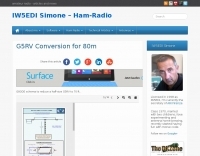 G8ODE schema to reduce a half-size G5RV to 70 ft.
 -
 The page describes the construction of a simple omnidirectional, vertically-polarised dipole antenna for two metres using coaxial cable. It can be used indoors or outdoors, with no extravagant gain claims. The project is low-cost and can be completed in about 20 minutes.
 -
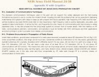
 Constructing a Lindenblad antenna for 137MHz NOAA satellite reception involves specific design considerations for optimal performance. The resource details the use of 4mm galvanised steel fencing wire, 300-ohm television ribbon cable, and wood/plastic components for the antenna structure. Key dimensions for a 137.58MHz-resonant antenna are provided, derived from the ARRL Satellite Handbook, specifying s, l, w, and d as 42, 926, 893, and 654mm respectively. The antenna is designed for Right Hand Circularly Polarised (RHCP) signals, requiring the four folded dipole elements to be tilted clockwise by 30 degrees. A significant aspect covered is impedance matching between the antenna's 75-ohm impedance and a typical 50-ohm receiver input. A twelfth-wave matching transformer, constructed from 117mm sections of 50-ohm RG-58 and 75-ohm RG-59 coax with a 0.66 velocity factor, is described. The article also addresses coaxial cable and connector selection, recommending 75-ohm Type-N connectors for RG-6 cable in professional setups and F56/F59 connectors for general use, while strongly advising against PL-259/SO-259 connectors for VHF. Strategies for mitigating Radio Frequency Interference (RFI) are discussed, including antenna placement to shield from local TV transmitters and the use of commercial or DIY band-pass filters, such as cavity resonators or helical notch filters, along with ferrite chokes on coaxial cables. Antenna orientation is explored, noting the Lindenblad's 'cone of silence' directly overhead and its maximized sensitivity towards the horizon. An experimental vertical tilt of 90 degrees is presented as a method to improve overhead reception and reduce interference from strong horizontal signals, particularly relevant in high RFI environments like the Siding Spring Observatory site.
 -
 This page describes two modifications W8WWV made to his AL-1200 amplifier. The mods were obtained from Ameritron, so they are official.
 -
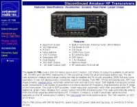 This page includes fatures, specifications options and photos of the ICOM IC-746
 -
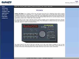 RadioQTH's Vanity Calls service provides a utility for US amateur radio operators to locate available vanity callsigns, specifically focusing on the shortest possible options. The system filters through all potential callsigns within a user's license class and presents only those currently unused, with results weighted by either their actual character length or their equivalent length in _Morse code_. This approach assists hams in securing memorable and efficient callsigns for CW operation. The service also lists recently granted vanity callsigns, sorted by prefix, offering insight into current FCC assignments. It clarifies the common misconception that callsigns are granted on a first-come, first-served basis, explaining the random selection process for applications received on the same day. The platform updates frequently, providing current data on available 1x2, 2x1, 2x2, 1x3, and 2x3 callsign formats, which are highly sought after by _Extra Class_ and _Advanced Class_ licensees.
 -
 The RigPix database entry provides a comprehensive technical overview of the Icom IC-746 amateur HF/VHF transceiver, detailing its operational parameters and physical characteristics. It specifies the transmit frequency ranges across 10-160 meters plus WARC bands, 50-54 MHz, and 144-146/148 MHz, alongside receive coverage from 0.03-60 MHz and 108-174 MHz. The resource outlines supported modes including AM, FM, SSB, CW, and RTTY, noting a tuning step resolution down to 1 Hz and a frequency stability of ±5 ppm. Key electrical specifications are presented, such as a 13.8 VDC power supply requirement, current drain figures for RX (1.8-2 A) and TX (Max 20 A), and RF output power ranging from 5-40 W for AM and 5-100 W for FM, SSB (PEP), and CW. The entry details the triple conversion superheterodyne receiver system, listing IF frequencies at 69.01 MHz, 9.01 MHz, and 455 KHz, along with sensitivity ratings for various modes and bands. Transmitter section specifics include modulation systems and spurious emission levels. Additional features like a built-in auto ATU, electronic keyer, simple spectrum scope, DSP, and CI-V computer control are noted. The page also lists related documents, modifications, and an extensive array of optional accessories, including various filters, microphones, and external tuners, providing a complete profile of the IC-746.
 -
 G4URH calculations to design your own antennas, ground plane, half wave antennas, Quad Antennas and 5/8 verticals
 -
 Manufacturers and distributors of coaxial surge protectors, coaxial switches, insultators, HF fixed wire antennas
 -
-
 Excel sheet containing technical comparisons of commercial HF portable antennas compiled by ON4SKY. Includes pictures, manufacturer, db gain, band coverage, F/B ratio, price, weight and dimensions.
 -
 A greyline map that automatically refreshes every five minutes DX.QSL.NET
 -

-
 Excel spreadsheet to input your old manual logbook data and have it converted to the ADIF format
 -
 Allow 137 Mhz range by Steve Warley
 -
 LOGvrr, a **freeware logging software** developed by IN3VRR, provides amateur radio operators with essential tools for managing their contacts. The resource details various downloadable components, including the core LOGvrr application, an international callbook with approximately 1.8 million callsigns, and utility programs for installation and data conversion. It supports functionalities like logging QSOs, managing awards, and interfacing with PacketCluster systems, with specific instructions for installation on Windows operating systems, including compatibility notes for Windows 10 and 11 using Hyper-V or DOSBOX. The site also offers external tools and documentation, such as the FAQ_VRR.PDF manual which covers installation, printer configuration, ADIF conversion, and Packet setup. It references third-party software like Mercurio and BV QSL Management for QSL printing, and ADIF2QSL for label printing, highlighting LOGvrr's ability to export QSOs in **ADIF format** for integration with services like LoTW. The resource includes historical updates, with the latest core component update in August 2014, and notes on the CallBook's maintenance up to 2015.
 -
 This resource details the computer-optimized design of the _ZS6BKW_ multiband dipole, an evolution of the classic _G5RV_ antenna. It begins by referencing the original 1958 RSGB Bulletin article by Louis Varney G5RV, explaining the operational principles of the G5RV's flat-top and open-wire feedline on 20m and 40m, noting its impedance transformation characteristics for valve amplifiers of that era. The article then transitions to the rationale for optimizing the design for contemporary solid-state transceivers requiring a 50 Ohm match. The core of the project involves using computer modeling to determine optimal lengths for the flat-top and matching section, aiming for a VSWR of less than 2:1 on multiple HF bands. It discusses the process of calculating feedpoint impedance based on antenna length and frequency, referencing professional literature from Professor R.W.P. King at Harvard University. The analysis also considers the characteristic impedance (Z(O)) of the open-wire line, identifying a broad peak of adequate values between 275 and 400 Ohms. Specific design parameters for the improved ZS6BKW are presented, including a shorter flat-top and a longer matching section compared to the original G5RV, with a velocity factor of 0.85 for the 300 Ohm tape. The article confirms acceptable matches on 7, 14, 18, 24, and 28 MHz bands when erected horizontally at 13m, and also discusses performance in an inverted-V configuration, noting frequency shifts. The author, Brian Austin ZS6BKW, emphasizes the antenna's suitability for modern 50 Ohm coaxial cable without a balun.
 -
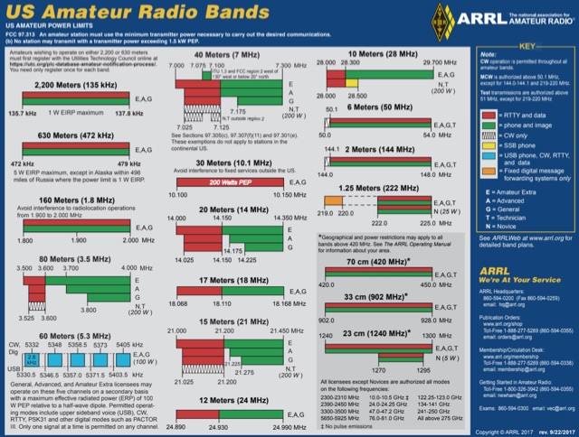 US Amateur Radio Band Plans by ARRL
 -

-
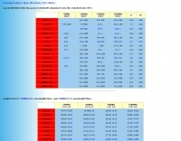 A table with Loss in DB/100m , Max power in Watts, Diameter in mm , Velocity factor (VF) expecially in VHF UHF and Microwave
 -
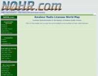 This amateur radio world map resizes the countries based on the number of licensed operators
 -
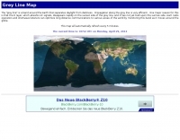
 For radio amateurs engaged in propagation studies and DXing on the 6-meter band, understanding the distribution of active beacons is crucial for assessing band openings and signal paths. This resource presents a static map compiled by _Carl-Axel Lindberg, SM6NZV_, illustrating the geographical placement of European beacons operating on the 50 MHz band, which is vital for monitoring sporadic-E, F2-layer, and other propagation modes. The map, last updated in April 2002, serves as a historical reference for beacon locations, allowing operators to correlate observed signal reports with known beacon positions. While not real-time, it provides foundational data for analyzing past propagation events and understanding typical beacon coverage areas across the European continent. Operators can use this information to identify potential receive stations or transmit points for future _DX contacts_ on the _Magic Band_.
 -
 The DXrobot, operational since 1999, offers a free, non-commercial service primarily for the VHF ham radio community. It specializes in automatic real-time E-skip warnings for **144 MHz** in both Europe and North America, delivered via email or SMS. Additionally, the system provides automatic aurora alerts for _50, 70, and 144 MHz_ openings through the same notification methods. Beyond real-time alerts, the DXrobot facilitates the reception of the latest DX-cluster spots via email, a feature useful for operators without immediate WWW or cluster access. The service also displays recent E-skip and aurora spots detected by the DXrobot on 50, 70, and 144 MHz, with updates every five minutes. Historical data includes lists of all DX spots from the previous day on 50, 70, and 144 MHz, updated daily. Key propagation data, such as MUF timeline, Solar X-rays, Geomagnetic Field, and Estimated Kp index, are also presented.
 -
 Amateur Television (ATV) operations, particularly within the Arizona region, require dedicated resources for technical information, operational guidance, and community engagement. This club provides a focal point for hams interested in transmitting and receiving video signals on amateur bands. Members engage in local ATV repeaters, participate in technical discussions, and share knowledge on video modulation schemes, antenna designs, and station configurations. The club supports activities ranging from local simplex contacts to wider area repeater usage, fostering skill development in this specialized mode. The organization maintains a roster of club officers and offers membership opportunities to local amateurs. It also curates offsite links to other ATV resources, expanding the knowledge base available to its members and the broader amateur community. The club's emphasis on ATV helps propagate interest and technical expertise in a mode that combines traditional RF engineering with video technology.
 -
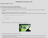 mods for the Yaesu FT-100 by radiomods.co.nz
 -
 Allow 9 bands and 1300 Watt output on the TL-922 amplifier with this document by PA0FRI
 -
 List of commnly used abbreviations in radio telegraphy communications
 -
 FindU.com operates as a robust database archiving **APRS** (Automatic Packet Reporting System) data, including weather, position, telemetry, and message reports. It integrates data from both amateur radio APRS systems and the internet-based Citizen Weather Observer Program. This substantial 58 GB database is hosted on dual servers utilizing data replication, processing approximately 20 new reports per second to provide constantly updated information. The system supports various applications, such as displaying weather reports, tracking position data, and facilitating long-term vehicle tracking. A notable function involves forwarding over 100,000 near-realtime weather observations daily to the National Oceanographic and Atmospheric Administration (NOAA) for accuracy checks and use by NOAA and the National Weather Service. Additionally, it archives APRS reports from the International Space Station. Access to the database is primarily via dynamic web pages, with a comprehensive list of available CGIs detailed on a dedicated server page. While direct URL parameter editing is possible for advanced users, alternative web pages with forms simplify query submission. The platform utilizes **PNG** images for dynamic graphics, a choice made due to past GIF patent issues, ensuring broad browser compatibility.
 -
 This program simulates a HF link, using sound card and WIN95 by Michael Keller, DL6iAK
 -
 Presents a comprehensive guide for constructing a broadband Hex Beam antenna, a popular directional array for HF operation. This design offers a compact footprint and excellent gain characteristics, making it suitable for limited space installations while providing significant performance advantages over omnidirectional antennas. The resource details the specific dimensions for a five-band Hex Beam covering 20, 17, 15, 12, 10, and 6 meters, emphasizing the critical element spacing and wire lengths required for proper resonance and pattern. It outlines the construction of the center post, spreaders, and wire elements, along with the feed point assembly, ensuring proper impedance matching. The project aims for a forward gain of approximately **5.5 dBi** on most bands, with a front-to-back ratio often exceeding _20 dB_. Building this antenna requires careful measurement and assembly, but the resulting performance provides a substantial upgrade for DXing and contesting.
 -
 The W1TAG LF Receiving Loop is a specialized antenna project for LF reception, designed to mitigate local noise and enhance weak signal pickup on the lower frequencies. This square loop, measuring 6 feet per side, utilizes 14 turns of #12 THHN wire wound on a PVC frame, offering a robust mechanical structure. The design incorporates a series-tuned circuit with a coupling transformer, allowing for tuning from over 400 kHz down to _45 kHz_ using a switched capacitor bank. Construction details include the use of 1.5-inch PVC pipe for the frame, with specific measurements for spreaders and drilled holes for wire threading. The two 7-turn sections of wire are connected at the center, providing an option for a center tap. The loop rotates on a 1-inch steel pipe, enabling directional nulling of noise sources. The tuning unit, housed in a box clamped to the PVC, employs a 1:2 step-up transformer wound on an _FT-82-77 core_ and uses relays to switch capacitance values from 50 pF to 6400 pF, providing precise frequency adjustment. The current setup connects to the shack via 100 feet of RG-58, feeding into a W1VD-designed preamp, with plans for a balanced, shielded twisted pair cable upgrade.
 -
 How to redirect the CAT to the MIC socket on the Yaesu FT-897/857
 -
 Provide components to the amateur who wants to construct their own gear and to the professional who wants to save money and time in prototyping their circuit design, Filters, HF Amplifiers, Splitter Combiners, VHF Amplifiers, ATV
 -
 Quick reference table on understanding A K SFI indexes and how can be translated in usable frequency opportunities
 -
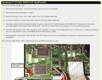
 The Kenwood TH-F6A handheld transceiver can achieve an extended transmit frequency range of 137-174 MHz, 216-235 MHz, and 410-470 MHz by removing a specific diode and chip resistor from the main PCB. This modification also expands the receive range on the A-band to 142-152 MHz, 216-235 MHz, and 420-450 MHz. For the TH-F7E, the transmit range extends to 137-174 MHz and 410-470 MHz, with a corresponding receive range on the A-band. Performing these hardware changes will reset and initialize the radio's memory contents, necessitating prior backup of important channel frequencies. Instructions are provided for constructing a homemade PC programming cable compatible with the Kenwood TH-G71A, TH-F6A, and TH-F7E. The interface utilizes an RS-232-to-logic (0-3.3V) level-shifter and a full-duplex serial connection, adapting the Kenwood PG-4S cable schematic for the TH-G71's 2.5mm and 3.5mm phono plugs. Specific schematic tweaks include changing R1 from 150 ohms to 1K ohm to optimize power from the serial port and adding a 150K ohm resistor between the Radio TXD and ground to manage the 3.3V I/O pin. Detailed plug pinouts for the 2.5mm and 3.5mm connectors are presented, with the interface's TXD connecting to the ring of the 2.5mm plug and RxD to the shield of the 3.5mm plug. Ground connects to the shield of the 2.5mm plug, while the tips of both plugs are no-connects. Debugging procedures cover verifying positive and negative power rails from the serial port, checking component polarities, and testing level-shifting and inversion functions of the interface. Software setup involves enabling "TC ON" (Menu 15 for TH-G71, Menu 9 for TH-F6) and using Kenwood's MCP programming software.
 -
 This article is a follow-up of Dallas Lankford's article Icom IC-746 Pro: Impressions and Mods, published on www.kongsfjord.no and (partially) in the Swedish Short Wave Bulletin.
 -
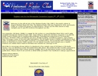 The National Radio Club is the world's oldest and largest Medium Wave DX club, founded in 1933.
 -
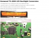 If the display lamps in your TS-2000 go out. They can be replaced with LEDs.
