Search results
Query: antenna cal.
Links: 1264 | Categories: 63
Categories
- Antennas > 20M > 20 meter Vertical Antennas
- Antennas > 40M > 40 meter Vertical Antennas
- Antennas > Antenna Calculators
- Radio Equipment > HF Vertical Antenna
- Manufacturers > Antennas > VHF UHF Microwave > Vertical Antennas
- Manufacturers > Antennas > HF > Vertical Antennas
- Antennas > 6M > 6 meter J-Pole Antenna
- Antennas > 6M > 6 meter Yagi Antennas
- Software > Antenna analysis
- Antennas > Theory > Antenna Gain
- Shopping and Services > Antennas
- Antennas > Vertical
- Technical Reference
- Antennas > 160M
- Antennas > 17M
- Antennas > 20M
- Antennas > 30M
- Antennas > 40M
- Antennas > 70cm
- Operating Modes > Satellites > AO-51
- Technical Reference > Arduino
- Radio Equipment > Antenna Analyzers > Array Solutions AIM 4170D
- Antennas > Bazooka
- Operating Aids > Beginner's Guides
- Shortwave Radio > Beginner's guides
- Ham Radio > Regional > Brazil
- Radio Equipment > HF Vertical Antenna > Butternut HF2V
- Antennas > C-Pole
- Shopping and Services > CB Radio Stores
- Radio Equipment > HF Vertical Antenna > Cushcraft R5
-
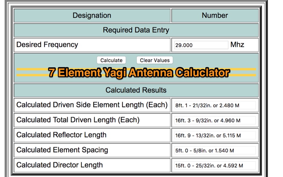 Online javascript antenna calculator designed to give the critical information of a particular beam antenna, in this case a seven element Yagi, for the frequency chosen.
 -
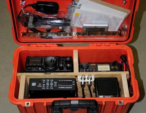 The best way to describe a go-box is a complete amateur radio station in a box. An example is described in this article. The project describes building a portable amateur (ham) radio station, known as a "go-box," housed in a durable orange Pelican case. The go-box contains all necessary radio equipment except for external power and antennae, which are carried separately. It includes items like a Yaesu transceiver, power supply, antenna tuner, speaker, and a clock. The case is designed for mobility and visibility, with a vertical layout to allow in-vehicle operation. Future upgrades might include cooling fans, an LED lamp, and built-in antennae for better functionality in various conditions.
 -
 Operating amateur radio satellites effectively requires precise knowledge of their orbital mechanics and pass times. Gpredict, a real-time satellite tracking and orbit prediction application, addresses this need by allowing operators to monitor numerous satellites simultaneously. It displays critical data such as position and pass details through various visualizations, including lists, tables, maps, and _polar plots_. Unlike many other satellite tracking programs, Gpredict introduces the concept of visualization modules. These modules enable users to group satellites and configure each group independently, offering unparalleled flexibility in how orbital data is presented. This modular approach supports tracking satellites from multiple observer locations concurrently, which is particularly useful for stations with diverse antenna setups or remote operations. Originally a GUI client for John Magliacane's _Predict_ program, Gpredict evolved to integrate its own tracking code for improved performance. The software is distributed under the GNU General Public License, ensuring it remains free and modifiable for the amateur radio community.
 -
 A slightly different 6M antenna project by N1GY, an Off center fed antenna for the 50 MHz.
 -
 A potpourri of 160-Meter vertical antennas and modeling issues, inverted-L, 3-element parasitic array, 1/4-wavelength monopole
 -

-
 Match & display imped of antennas, can graphically visualize and compare two sets of measured impedances simultaneously.
 -
-
 A vertical linear loaded antenna for 2 meters band in italian
 -

-
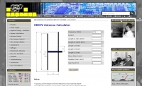 Calculate dimension for HB9CV directional antennas
 -
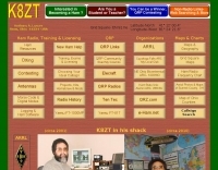 The K8ZT website provides a curated collection of amateur radio resources, encompassing software tools, informational articles, and external links relevant to various aspects of the hobby. It features utilities for _log analysis_, insights into QRP operations, and guidance on obtaining vanity callsigns. The site also includes sections dedicated to shack design principles and general ham radio information, reflecting a broad interest in practical station setup and operational enhancements. Specific software offerings are presented alongside discussions on their application, such as tools for analyzing contest logs to identify operational efficiencies or areas for improvement. The content often integrates personal experience with technical explanations, providing a practical perspective on topics like antenna selection for low-power operations or optimizing station workflow. The resource distinguishes itself by combining software recommendations with contextual information, aiding operators in making informed decisions about their station's technical and operational aspects.
 -
 A javascipt online calculator for 2 and 3 element beam antennas. Just input frequency and will diplay element dimensions and spacing. Measurements in Feet and Meters by G4VWL
 -
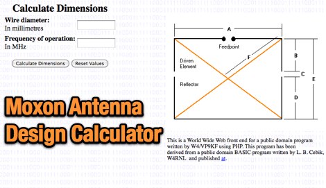 Online Moxon antenna calculator. Design your moxon antenna online giving wire diameter and resonant frequency
 -
-
 Constructing a linear focus parabolic antenna for WiFi operation involves precise metalwork, as detailed in this project. The author, AB9IL, shares a build that can be completed in a few hours, emphasizing the hands-on process of shaping and assembling metal components. This design aims to provide enhanced signal range for 2.4 GHz wireless networks, a common challenge in many ham shacks and home setups. The project outlines the practical steps required, from initial measurements to the final assembly, including cutting, bending, and bolting various metal parts. While specific gain figures are not provided, the parabolic design inherently offers significant _directional gain_ compared to omnidirectional antennas, making it suitable for point-to-point links or extending network coverage over distances. The construction process focuses on readily available materials and basic shop tools, aligning with the DIY spirit prevalent in amateur radio. This antenna project is presented as a straightforward build, requiring attention to detail in fabrication to achieve optimal performance.
 -
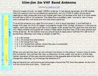 This VHF 145 MHz antenna is easy to build and with no radials. It shows equal gain of 5/8 lambda. It is light weight, you can hang it somewhere (on a tree may be) and work.
 -
 The Super J Pole antenna is a co-linear vertical consisting of a number of half wave length vertical elements separated with half-wave length stubs (Tuning stub) feed with a folded matching stub by vk6ysf
 -
 Theory, Modeling, and Practical Applications By W5JCK, presentation in PDF File. This presentation focuses on Near-Vertical Incidence Skywave (NVIS) antennas, which are crucial for short-range radio communications, particularly in military and emergency contexts. It explores NVIS theory, antenna models, and installation criteria while debunking common myths about reflectors. Key topics include usable frequency bands, optimal installation heights, and the impact of soil quality on performance. The presentation outlines the best bands for daytime and nighttime use, emphasizing the importance of understanding propagation characteristics to enhance communication effectiveness within 200 to 300 miles.
 -
 The document details the optimization and construction of the _Maria Maluca_ antenna, a compact 6-band (20m-6m) directional beam. It presents a comparative analysis of shortwave antenna principles, highlighting the efficiency gains achieved by using an open feeder line and tuner as a resonant unit, contrasting this with the losses associated with traps or capacitive loads in multiband antennas. The resource specifically revisits an older South American 2-element design for 10, 15, and 20 meters, applying modern NEC-based software to develop a six-band version. Performance data is meticulously tabulated, showing impedance, free space gain, gain at 12m height, elevation angle, and front-to-back (F/B) ratio for each band from 20m through 6m. For instance, on 15m, the antenna achieves 5.1 dBd free space gain and 13.72 dB F/B ratio. The construction section provides practical guidance on element assembly using aluminum pipes and hose clamps, detailing the use of a heavy-duty glass fiber reinforced polyamide rod for electrical separation and bending strength. It also specifies the use of 450-ohm _Wireman_ line CQ 552 for the transmission line. The document includes diagrams for rod fixing, an air-wound balun, and a vertical elevation diagram for the 15m band, illustrating its DX qualification. It also discusses the antenna's suitability for portable and expedition operations, noting its compact transport dimensions (max 1.50m length, 12 lb weight) and quick assembly time (under 15 minutes). The author, Dipl.Ing. Helmut Oeller, DC6NY, is identified as a source for material kits.
 -
 Comparison chart between Cushcraft R8, Hy-Gain AV640 , Butternut HF6V, Gap Titan and Eco 7+
 -
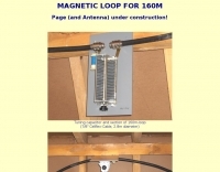 Pictures and calculated values for this home made magnetic loop antenna for the 160 meters band by HB9MTN
 -
 The article "Exploring the World of 10 Meter Beacons" by Ken Reitz, KS4ZR, provides an in-depth look at 10-meter beacon operations, focusing on their utility for propagation analysis. It details FCC Rules part 97.203 governing beacon stations, including license requirements, power limits (under 100 watts), and the specified band segment of 28.200-28.300 MHz for U.S. operations. The content highlights the diversity in beacon construction, from converted CB radios to home-brew QRP transmitters, and discusses the robust operating conditions these 24/7 stations endure. The resource presents several case studies of active 10-meter beacon operators like Ron Anderson KA0PSE/B, Domenic Bianco KC9GNK/B, and Bill Hays WJ5O/B, detailing their equipment, antenna setups, and typical signal report volumes. It also introduces the NCDXF/IARU International Beacon Project, which features 18 synchronized beacons worldwide transmitting on 28.200 MHz at varying power levels (100W, 10W, 1W, 100mW) to facilitate propagation testing. The article also covers the PropNet Project utilizing PSK31 on 28.131 MHz and the 250 Synchronized Propagation Beacon Project on 28.250 MHz. Practical advice for monitoring includes using the RST reporting method, understanding the impact of the solar cycle on 10-meter propagation, and tips for setting up a personal beacon, such as frequency selection and power output considerations. The IY4M Guglielmo Marconi Memorial Beacon Robot on 28.195 MHz is also mentioned for its automatic QSO mode. The article concludes with a list of other resources for 10-meter beacon information.
 -
 The G5RV antenna, a popular multi-band wire antenna, typically employs a center-fed design with a specific length of 300-ohm or 450-ohm open-wire line acting as an impedance transformer, feeding a coaxial cable run to the shack. Its overall length for 80-10 meters is approximately 102 feet (31 meters) for the flat-top section, with a 34-foot (10.36 meter) matching section. The original design by Louis Varney, G5RV, aimed for efficient operation on 14 MHz (20 meters) as a 3-half-wave antenna, with the matching section providing a good match to 50-ohm coax on that band. While the G5RV offers multi-band capability, its performance varies across bands, often requiring an antenna tuner for optimal SWR on bands other than 20 meters. The matching section's length is critical for its impedance transformation properties, influencing the feedpoint impedance presented to the coaxial cable. Variations like the G5RV Junior and ZS6BKW utilize different flat-top and matching section lengths to optimize performance for specific band sets or to achieve a lower SWR without a tuner on certain bands, demonstrating the adaptability of the basic G5RV concept.
 -
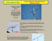 For two purposes a Cross-Yagi can be useful Satellite work or if you need both vertical and horizontal polarization for terrestrial contacts
 -
 A portable dualband dipole robust and compact antenna usable for horizontal and vertical polarisation by ON6MU
 -
 It consists of a group of JavaScript driven web pages that are intended for use as a quick reference for Ham Radio operators or just anyone interested in electronics. Offer calculators for Resistors, capacitors, inductors, power supplies, filters, attenuators and antennas
 -
 A simple drawing of a shortened antenna for 40 meters by using a PVC tube
 -
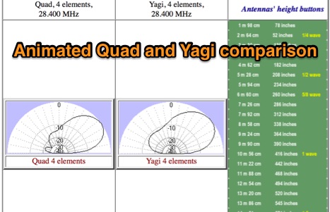 Animated quad and yagi comparison. You can see antennas' characteristics behavior in a vertical plane with changing of the height.
 -
 Simple DIY stealth apartment antenna for 20m and 40m. It is basically a ZigZag quarter wave dipole antenna
 -
 Article on the HF dual band antenna with construction details and how to add 160 meters to the HF2V
 -
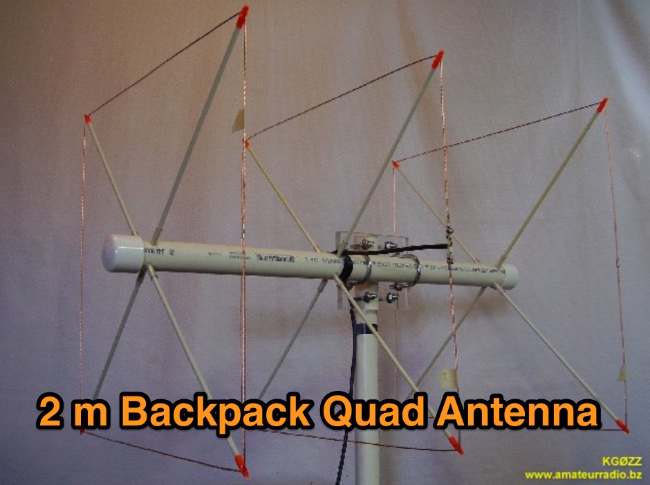 This 2 meter 3 element cubical quad antenna is small, light weight and portable. A backpack antenna that is easy to put together in just minutes and parts store inside the boom making it ready for travel or storage.
 -
 A 40 ft vertical dipole antenna that can cover HF Bands from 80 to 10 meters winding a dipole in a 12m HD telescoping fiberglass pole
 -
 The Charles Gizmotchy high performance horizontal and vertical beam antennas. Two, Six, Ten and eleven meters antennas
 -
 The Screwdriver Antenna Memory (SAM) product is designed to enhance the mobile antenna commonly called the "Screw Driver". It replaces your current control unit and provides an automated memory feature that eliminates the visual coil tuning method commonly used.
 -
 How to make a loading coil for the AD5X portable vertical antenna
 -
 A quarter-wave vertical antenna design for HF operation offers a practical solution for radio amateurs seeking a compact and efficient multi-band radiator. This project details the construction of a 5-band HF vertical, drawing inspiration from established commercial products such as the _DX COMMANDER_ and the MV6. The design emphasizes ease of assembly and disassembly, making it suitable for portable operations or installations with limited space. The article provides insights into various construction methods and offers practical tips for building a robust yet lightweight antenna. It highlights the benefits of a vertical configuration for DX contacts, particularly on the lower HF bands, and discusses real-world performance observations. The antenna is designed to cover multiple HF bands, providing versatility for various operating scenarios. Operators can achieve significant DX results with this type of antenna, often comparable to more complex arrays, especially when deployed with an effective ground system. The project aims to empower hams to build a capable antenna without significant financial outlay.
 -
 Homebrew a vertical antenna for 40 and 80 meters band based on popular HF2V model by DL7JV
 -
 1/2wave vertical antenna for the 6-meterband and a 5/8 ground plane antenna for 50 Mhz
 -
 The page describes the construction of a simple omnidirectional, vertically-polarised dipole antenna for two metres using coaxial cable. It can be used indoors or outdoors, with no extravagant gain claims. The project is low-cost and can be completed in about 20 minutes.
 -
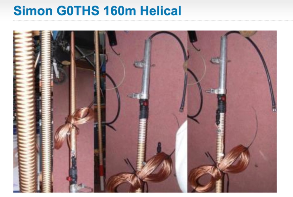
 A vertical antenna for the top band, made with a 26m fiberglass spiderpole by DJ0IP
 -
 Don't buy or build a semi-vertical trap antenna until you read this article! If you can use a drill, saw and screwdriver this is a simple project.
 -
 Homebrew a 2 meter 1/4 wave vertical antenna for the 146 mHz ham radio band
 -
 An homemade portable vertical antenna with a trap near the mid point of the main element. The trap is made with 42mm diameter PVC pipe with 9 turns of wire on it
 -
 Constructing a compact, two-band magnetic loop antenna for HF operation, especially from constrained locations like a balcony, presents unique challenges. OK1FOU's design, inspired by DJ3RW's 50 MHz loop, addresses these by employing an unusual side-fed configuration and placing the symmetric, two-section variable tuning capacitor at the bottom of the loop, directly connected to the coax shield. The article provides specific material recommendations, including two 1-meter wooden pales and about 3 meters of thick loudspeaker cable, noting the high current (60A at 100W) in the loop. Construction steps detail forming two turns with a 5 cm gap, using a GDO to pre-tune the open loop to a frequency slightly above the desired highest band, and then integrating the tuning and coupling capacitors. For 10/14 MHz, an open loop resonance of 16-17 MHz is suggested. Practical experience with the 10 MHz band from a third-floor balcony in Prague (JO70GC) shows a 1:1 SWR across most of the band without an external ATU. While DX traffic was modest due to the urban environment, QSO examples with RA6WF, LA6GIA, G0NXA, and LZ1QK on 10 MHz are provided, demonstrating its operational capability.
 -
 Constructing a Lindenblad antenna for 137MHz NOAA satellite reception involves specific design considerations for optimal performance. The resource details the use of 4mm galvanised steel fencing wire, 300-ohm television ribbon cable, and wood/plastic components for the antenna structure. Key dimensions for a 137.58MHz-resonant antenna are provided, derived from the ARRL Satellite Handbook, specifying s, l, w, and d as 42, 926, 893, and 654mm respectively. The antenna is designed for Right Hand Circularly Polarised (RHCP) signals, requiring the four folded dipole elements to be tilted clockwise by 30 degrees. A significant aspect covered is impedance matching between the antenna's 75-ohm impedance and a typical 50-ohm receiver input. A twelfth-wave matching transformer, constructed from 117mm sections of 50-ohm RG-58 and 75-ohm RG-59 coax with a 0.66 velocity factor, is described. The article also addresses coaxial cable and connector selection, recommending 75-ohm Type-N connectors for RG-6 cable in professional setups and F56/F59 connectors for general use, while strongly advising against PL-259/SO-259 connectors for VHF. Strategies for mitigating Radio Frequency Interference (RFI) are discussed, including antenna placement to shield from local TV transmitters and the use of commercial or DIY band-pass filters, such as cavity resonators or helical notch filters, along with ferrite chokes on coaxial cables. Antenna orientation is explored, noting the Lindenblad's 'cone of silence' directly overhead and its maximized sensitivity towards the horizon. An experimental vertical tilt of 90 degrees is presented as a method to improve overhead reception and reduce interference from strong horizontal signals, particularly relevant in high RFI environments like the Siding Spring Observatory site.
 -
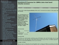 The Homebase10 is a simple to make wire halo antenna for 10m (28MHz) built using parts available from the local DIY store.The resulting antenna is very effective on 10m despite its small size and light weight.
 -
 A circular waveguide calculator for designing cantennas include source code and windows executable by lincomatic
 -
 G4URH calculations to design your own antennas, ground plane, half wave antennas, Quad Antennas and 5/8 verticals
 -
 The idea of using a low mount dipole, enhanced with reflector wires directly beneath the dipole, on the ground, appears to be a very good approach to creating an NVI specific antenna for local HF operation.