Search results
Query: HF antenna
Links: 899 | Categories: 40
Categories
- Radio Equipment > HF Vertical Antenna
- Radio Equipment > HF YAGI Antennas
- Shopping and Services > Antennas > VHF Antenna
- Radio Equipment > HF Portable Antenna
- Radio Equipment > HF Vertical Antenna > Butternut HF2V
- Manufacturers > Antennas > VHF UHF Microwave > Discone Antennas
- Manufacturers > Antennas > HF
- Manufacturers > Antennas > VHF UHF Microwave > Mobile Antennas
- Manufacturers > Antennas > VHF UHF Microwave > Quad Antennas
- Manufacturers > Antennas > HF > Quad Antennas
- Manufacturers > Antennas > HF > Small & Stealth Antennas
- Radio Equipment > HF Portable Antenna > Super Antennas MP-1
- Radio Equipment > HF Portable Antenna > TransWorld Antennas TW2010
- Manufacturers > Antennas > VHF UHF Microwave > Vertical Antennas
- Antennas > VHF UHF
- Manufacturers > Antennas > VHF UHF Microwave > Yagi Antennas
- Manufacturers > Antennas > HF > Yagi Antennas
- Manufacturers > Antennas > VHF UHF Microwave
- Manufacturers > Antennas > Broadcast
- Antennas > CobWebb
- Antennas > Collinear
- Radio Equipment > HF YAGI Antennas > Cushcraft A3S
- Radio Equipment > HF YAGI Antennas > Cushcraft MA5B
- Radio Equipment > HF Vertical Antenna > Cushcraft R5
- Radio Equipment > HF Vertical Antenna > Cushcraft R7
- Radio Equipment > HF Vertical Antenna > Cushcraft R8
- Antennas > Handhelds
- Radio Equipment > HF Vertical Antenna > Hustler 5-BTV
- Manufacturers > Antennas > HF > Magnetic Loop
- Radio Equipment > HF Vertical Antenna > Maldol MFB-300
-
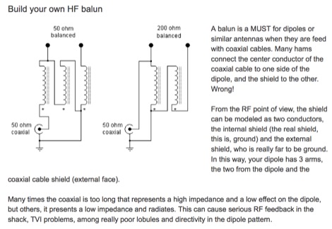 A balun is a MUST for dipoles or similar antennas when they are feed with coaxial cables. Many hams connect the center conductor of the coaxial cable to one side of the dipole, and the shield to the other. Wrong!
 -
 High End isopole VHF & UHF antennas for Amateur, Commercial and Military applications.
 -
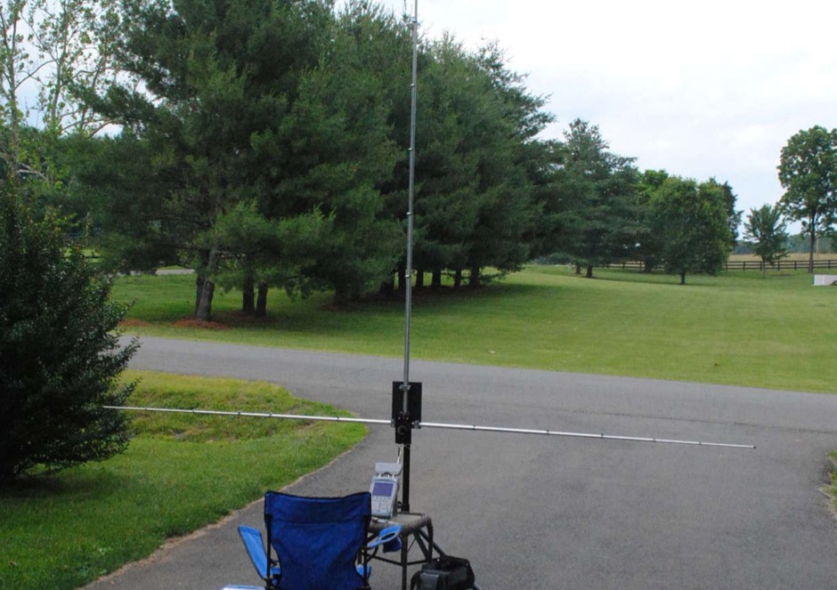 This article describes a project of asymmetrical hatted vertical dipole, a portable antenna that can be used for field day operations, sota, campings or even for fixed installations. This is a freestanding 20-10m antenna that is really easy to build, easy to tune and relatively easy to carry.
 -
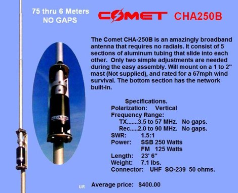 An interesting article by K3DAV comparing the COMET CHA250B to other HF multiband vertical antennas
 -
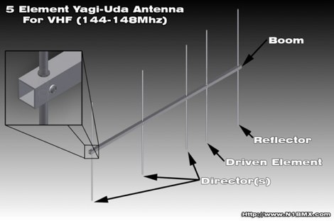 A project for a home made 5 element yagi-uda antenna for 2 meters, covering 144-148 MHz band by N1BMX
 -
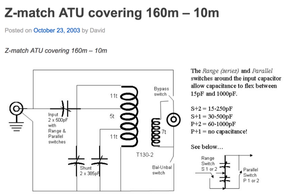 An home made Z-Match antenna tuner unit that cover all HF bands between 10 and 160 meters
 -
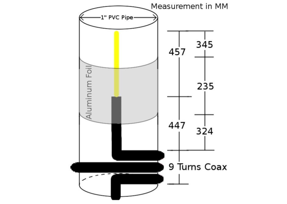 A homemade VHF/UHF vertical antenna made essentially with RG58 coax cable, with a 9 turns choke balun to prevent the shield acting as a RF Radiator.
 -
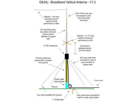 Broadband HF Vertical antenna which does not require a tuner, and which is capable of providing reasonable performance on all bands from 7MHz to 28MHz
 -
 An engineering oriented organization specializing in the design and manufacture of high performance parabolic antennas, 3dB high power RF couplers, Antenna power splitters, directional RF couplers and more items for RF transmission from HF through Microwave frequencies.
 -
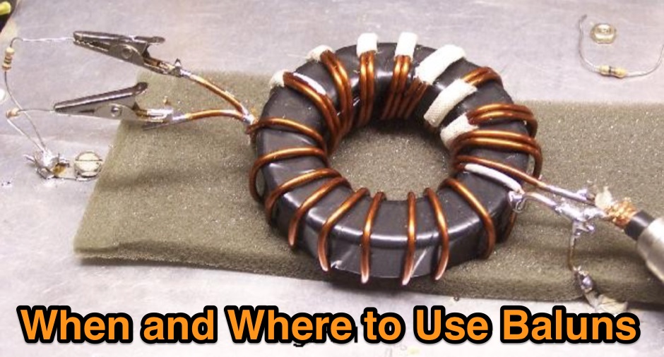 The document provides a comprehensive overview of baluns, which are devices used to connect balanced loads, like dipole antennas, to unbalanced inputs, such as coaxial cables. It covers various types of baluns, including voltage and current baluns, and their design, construction, and testing. The text discusses the importance of baluns in preventing RF currents on coax shields and their applications in Ham radio setups. It also includes practical advice on selecting and using baluns based on antenna impedance and power ratings, along with detailed performance evaluations and construction tips for different balun configurations.
 -
 Specialists in shortwave radio, scanners, amateur radio, FRS (family radio), CB radio, antennas, accessories and publications since 1995.
 -
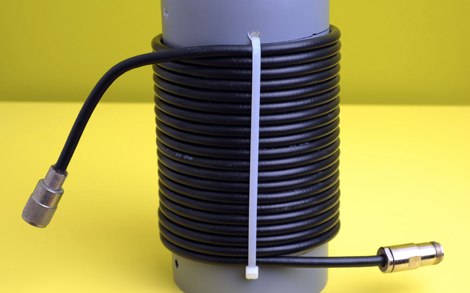 Are you having RF problems in the shack since you put up your HF vertical antenna? This is a common problem with an easy solution.
 -
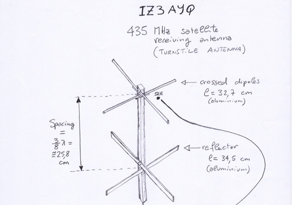 A UHF antenna for satellite reception. Anntenna mast is in wood, made with two aluminium rods
 -
 YF1AR multiband vertical antenna, based on orginal concept by VE7BS. Consist of 6 vertical elements and 6 base radials with a single 50 Ohm feed line.
 -
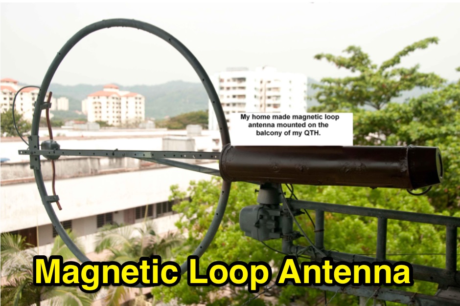 If you have space constraint at your QTH for a HF antenna, you can try contructing this HF magnetic loop antenna for 40-20 meters bands
 -
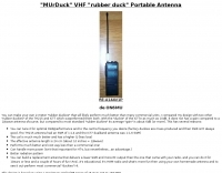 You can make your own 2-meter "rubber duckies" that will likely perform much better than many commercial units.
 -
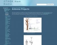 This is a design for a stealthy HF multi-band vertical wire antenna using a tree as a supportby G7AQK
 -
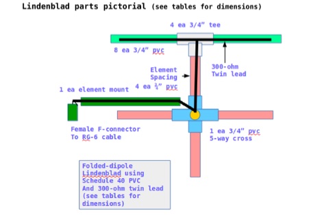 This document contains the detailed instructions to build a homemade lindenblad antenna using a twin-lead as dipole elements. This document contains 9 pages and includes a detailed construction sequence and some drawings to build this antenna for UHF and VHF ham radio bands
 -
 Cheap UHF antenna plans for 2 meters and up including 421 1296 and 902 Mhz
 -
 The G5RV multiband HF antenna, designed by Louis Varney (G5RV) in 1946, is a popular compromise antenna offering good overall performance on most HF bands when paired with an external antenna tuner. The basic full-size G5RV measures 102 feet across the top for 80 through 10 meter operation and is fed at the center via a 34-foot low-loss feed-stub. This interaction between the radiating section and the feed-stub facilitates matching across 80-10 meters with a standard tuner, often eliminating the need for ladder line directly to the shack. The antenna's design center frequency is 14.150 MHz, configured as a 3/2-wave dipole on 20 meters, with its 102-foot length derived from long-wire antenna formulas. Construction details emphasize the matching section, which can be open wire, ladder line (window-type), or TV twin lead. Each type has a specific velocity factor (VF) affecting its physical length for an electrical half-wave on 14 MHz; for instance, open wire requires 33.7 feet (VF 0.97), ladder line 31.3 feet (VF 0.90), and TV twin lead 28.5 feet (VF 0.82). The article provides formulas for calculating these lengths and discusses the antenna's behavior on individual bands, from 3.5 MHz where it acts as a shortened dipole, to 28 MHz where it functions as two three-half-wave long-wire antennas fed in-phase. Practical construction notes include recommendations for vertical descent of the matching section, sealing the coax junction, providing strain relief, and winding a coaxial choke coil to mitigate common mode current. The resource also presents dimensions for double-size (204 ft) and half-size (51 ft) G5RV versions, along with their corresponding matching section lengths for various line types, making it a versatile reference for hams considering this classic wire antenna.
 -
 Offer a wide range of homebrewing projects mainly for VHF UHF operations. From vhf antennas to preamplifiers, chargers and power supplies
 -
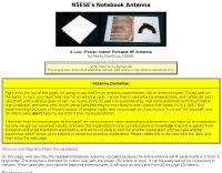 A Low -Power Indoor Portable HF Antenna by Monty Northrup, by N5ESE
 -
-
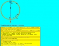
 A New Twist on Portable Multiband HF Dipoles, a Multi-band Spiral Dipole Off-Center-Feed match (OCF) antenna solution.
 -
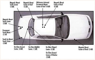 Mobile antenna placement presents unique challenges for the amateur radio operator, often requiring compromises between RF performance and mechanical considerations. This resource from KV5R.COM offers practical insights into achieving effective installations, drawing on real-world experience with different vehicle types. It details how factors like ground plane availability, proximity to vehicle structures, and antenna type (e.g., **HF mobile**, **VHF/UHF mobile**) influence signal radiation patterns and overall system efficiency. The author discusses common scenarios, from sedans and SUVs to trucks and RVs, highlighting the impact of mounting locations such as the trunk lip, fender, or roof. Specific attention is given to minimizing RF interference and maximizing radiated power, crucial for reliable mobile communications. Understanding the interaction between the antenna and the vehicle's metallic body is key to a successful mobile setup, and this content provides a solid foundation for making informed decisions.
 -
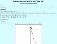 A vertical monoband antenna design that can work from 6 meters to 70 cm by F5ZV in French
 -
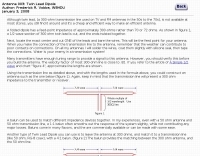
 The GW3YDX Super Moxon antenna design improves upon the standard Moxon Rectangle by incorporating additional directors in a rectangular configuration, yielding enhanced directivity and gain. For the 6m version, modeling with 4NEC2 and EZNEC+ indicated a 3dB gain increase and a 26.5dB front-to-back ratio, with VSWR below 1.5:1 between 50.0 and 50.3MHz when optimized for 50.1MHz. This design achieves a narrower -3dB power point beamwidth of 60° compared to the original Moxon's 80°, contributing to better QRM rejection. The boom length for the enhanced design is just under 2m, approximately double the original Moxon's, with no increase in wingspan. Construction details include tubing lengths for 6m, 4m, and 2m versions, with specific dimensions provided for elements A through M, measured to tubing centers. For instance, the 6m version uses a 2160mm element A and a 2140mm element H. The design maintains a 50-ohm feed impedance, with practical models showing VSWR plots consistent with simulations after minor adjustments to driven element lengths. The article also references Moxgen software for initial Moxon parameter calculation and NEC/EZNEC model generation. The 2m Super Moxon version measures approximately 30" x 25", demonstrating the compact nature of the design across different VHF bands. The article highlights the antenna's performance in real-world DX contacts on 6m, achieving contacts with over 80 stations in the USA from a modest QTH.
 -
-

-
 Manufacturer of single band and multiband transceiver bandpass filters for HF. High pass filters, two radoi headphones mix and switch, 6 meter portable antenna, antenna remote switching and steering.
 -
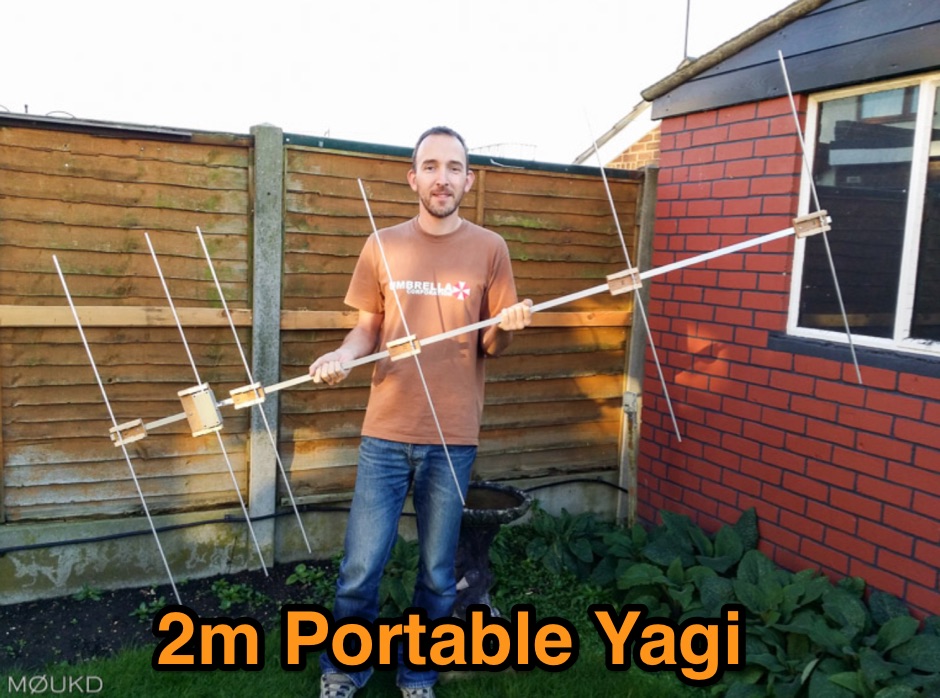 Building a 2 metre 144MHz VHF Yagi beam antenna, designed for portable use.
 -
-
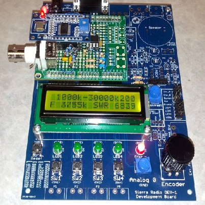 This article explain how to homebrew and use an HF antenna analyzer by simply adapting a Windows PC, micro-controller and a DDS evaluation board by K6BEZ
 -
-
 Located in southern Ontario Canada, supplier for HF VHF antenna kits, aluminium tubing, portable j-pole antennas, lightning suppressors, connectors and adapters
 -
 VHF UHF diplexer by G8MNY
 -
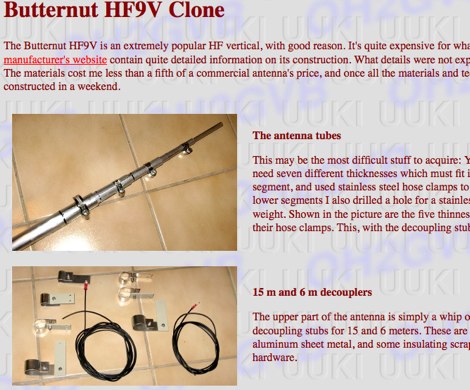 An home made Butternut HF9V clone antenna by OH2GVB
 -
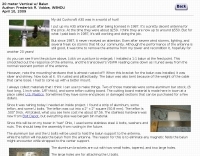 A method for supporting a balun on a Chushcraft A3S antenna. This allows the balun to be isolated from the boom, thus reducing the effect of introduction of reaction with the balun core.
 -
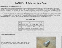 The resource details the construction of a **Hustler-compatible** HF mobile antenna mast, utilizing 1/2-inch copper water pipe and common hardware. It provides a bill of materials, specifying one 10-foot copper pipe, four 1/2-inch copper end caps, and 3/8-inch fine-thread hex bolts and nuts, totaling $8.75 for two masts. The construction process outlines preparing bolts by rounding their heads, drilling 3/8-inch holes in end caps, soldering bolts into caps, and then soldering these cap/bolt assemblies to 5-foot sections of copper pipe to achieve a final length of 54-1/4 inches per mast. The method emphasizes precise soldering techniques to ensure structural integrity and proper fit. The resulting masts are presented as functional alternatives to commercial units, with the author noting their performance is comparable to the "real thing." Installation tips are provided, including the use of braces connected to a trunk lid to mitigate stress on the antenna mount, contrasting this approach with WA8WTE's spring-based method. Photos illustrate the completed mast mounted on a vehicle, demonstrating practical application and support strategies for mobile HF operation, particularly with larger coils and longer whips at highway speeds.
 -
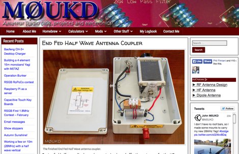 Centre fed half wave dipoles make great, simple and effective antennas for the HF bands. Sometimes however, the centre feed is not ideal. This great project will improve the overall antenna performance.
 -
 This article describes a simple Inverted L antenna for the HF bands designed to work on 80m, 40m, 30m and 20m
 -
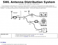 a methodology for connecting multiple LF/MF/HF receivers to a single antenna via readily available and inexpensive 75-ohm TV cable.
 -
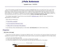 An easy portable VHF antenna to build for ARES - RACES work is the 300 Ohm Twin Lead JPole antenna
 -
 Demonstrates the construction of a _3MA triband mobile antenna_ designed by IZ7DJR, emphasizing a full-size quarter-wave whip for 10 meters. The design incorporates a rapid tilt-down mechanism to facilitate quick changes of loading coils for operation on 15 and 20 meters. This approach aims to minimize losses and enhance efficiency compared to conventional base-loaded mobile antennas. The resource provides specific coil winding data: 22 turns for 15 meters and **37 turns** for 20 meters, both using 1mm wire over an 80mm coil length. The 10-meter band operates without a loading coil, leveraging its full-size design. The author's design prioritizes ease of band switching and improved performance for mobile HF operations, offering a practical alternative to more lossy commercial options.
 -
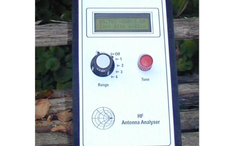 This antenna analyzer measures complex impedance over the 1.6 - 33 MHz HF spectrum
 -
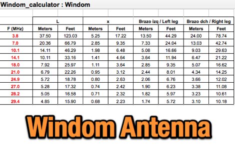 This article describes the characteristics of the Windom antenna and shows the results of several simulations made with MMANA-GAL, covering models optimized for the 20 m, 40 m and 80 m bands.
 -
 This article explores the performance of an unloaded elevated vertical, base matching and feed line as a multi-band HF antenna system.
 -

-
 A 5 band two element quad antenna working from 20 to 10 meters using hardware-store parts or modifying an existing commercial triband quad by KC6T
 -
 This article explores the performance of an unloaded vertical as a multi-band HF antenna.