Search results
Query: antennas for 2 meter
Links: 287 | Categories: 19
Categories
- Antennas > 20M > 20 meter Dipole Antennas
- Antennas > 20M > 20 meter Vertical Antennas
- Antennas > 20M > 20 meter Yagi antennas
- Antennas > 40M > 40 meter Dipole Antennas
- Antennas > 40M > 40 meter Loop Antennas
- Antennas > 40M > 40 meter Magnetic Loop Antennas
- Antennas > 40M > 40 meter Vertical Antennas
- Antennas > 6M > 6 meter Yagi Antennas
- Antennas > 6M > 6 meter Moxon Antennas
- Antennas > 40M > 40 meter Delta Loop Antennas
- Antennas > 40M > 40 meter Yagi Antennas
- Antennas > 6M > 6 meter J-Pole Antenna
- Antennas > 15M
- Antennas > 20M
- Antennas > 40M
- Antennas > 60M
- Antennas > 80M
- Antennas > Halo
- Antennas > Morgain
-
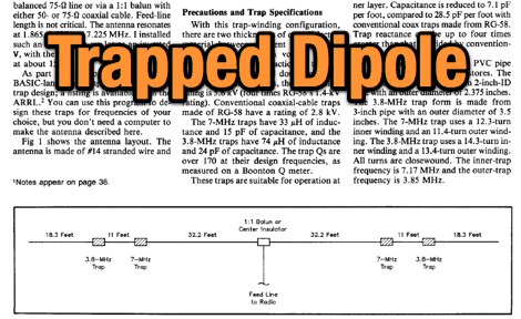 Build a space efficient trapped dipole antenna for 40-80-160 meter bands using RG-58 and PVC pipe. The document provides a brief guide on building a compact dipole antenna appropriate for the 40, 80, and 160-meter amateur radio bands. It explains the materials, building processes, and tuning methods required to provide best performance while preserving space. The paper also discusses theoretical elements of dipole antennas, such as impedance matching and feedline selection.
 -
 Demonstrates the construction of a **multi-band HF mobile antenna** utilizing a modified CB whip antenna base. The resource details the process of stripping a commercial CB whip, winding a new helical coil with 0.7mm insulated copper wire, and identifying tapping points for various HF bands. It emphasizes the importance of a rugged, slim design for mobile operation, discussing mechanical length, power handling (up to 200 watts), and coil diameter considerations. The article includes a graphic illustrating the antenna's operational principle, where sections of the helical coil are shorted from bottom to top to maintain efficiency and high Q. The resource presents a practical approach to achieving **band switching** without an external tuner, by manually adjusting tapping points on the coil. It provides a table with reference lengths in centimeters from the feedpoint for 7 MHz (40m) through 28.7 MHz (10m), including WARC bands. The author details mounting techniques, suggesting a Diamond bracket for secure attachment to a vehicle trunk, and stresses the critical role of proper grounding for optimal performance. The design allows for operation on 75m and 80m bands by adding a 110mm steel whip.
 -
 This resource provides a detailed guide on constructing a J-pole antenna specifically for the 2 meter band, which is popular among amateur radio operators. The article outlines the materials needed, including various sizes of aluminum pipes and PVC, as well as the tools required for assembly. It emphasizes the simplicity and effectiveness of the J-pole design, making it an ideal choice for newcomers to amateur radio. The instructions are straightforward, allowing users to build the antenna in less than an hour, and include tips for tuning the antenna for optimal performance. In addition to the construction details, the resource includes practical advice on the assembly process, such as how to cut and join the pipes, as well as how to mount the SO239 connector. The author shares personal experiences and insights on achieving a low standing wave ratio (S.W.R.) and suggests modifications for creating bi-band or tri-band J-pole antennas. This comprehensive guide is enriched with photographs that illustrate the construction steps, making it easier for users to follow along and successfully build their own J-pole antenna.
 -
 Cubic quad antennas are renowned for their high gain, excellent front-to-back ratios, and low angles of radiation, making them a popular choice among amateur radio operators. This resource provides detailed designs for constructing cubic quads optimized for 2, 6, 10, 12, and 15 meter bands. The lightweight structure can be easily built using fiberglass tubes and central hubs, allowing for portability and ease of assembly. The article discusses the specific dimensions and configurations required for both HF and VHF applications, emphasizing the importance of proper spreader lengths and boom dimensions. It also highlights the challenges of assembling larger cubic quads in limited spaces, offering practical solutions for hams with smaller backyards. With a focus on multi-band operation, this guide serves as a valuable resource for both novice and experienced operators looking to enhance their antenna systems.
 -
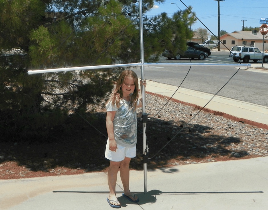 The 160/80m coaxial receiving loop antennas are designed to enhance reception on the top bands while minimizing noise. These antennas are particularly beneficial for operators with limited space, as they can be constructed using lightweight materials, making them portable and easy to deploy. The standalone 80m loop has a diameter of approximately four feet, allowing for easy rotation and installation above existing VHF antennas. Over the years, many amateur radio operators have turned to loop antennas as a viable alternative to traditional beverage antennas. The design allows for significant noise reduction, especially when paired with a quality pre-amplifier. Experimentation with various configurations has led to the discovery that diamond-shaped loops provide optimal performance. Users have reported a noticeable improvement in signal quality, making these loops a valuable addition to any low-band DXing setup.
 -
-
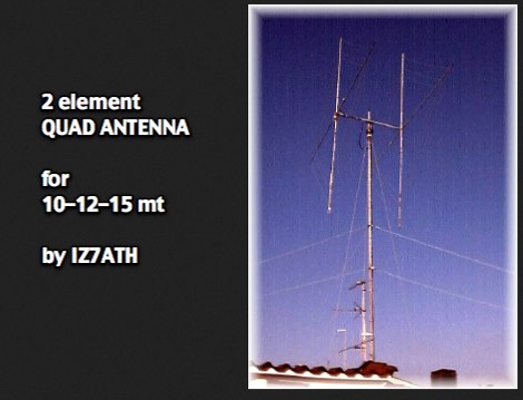 This resource provides comprehensive instructions for constructing a 2 element quad antenna specifically designed for the 10, 12, and 15 meter bands. The antenna features a diamond configuration, which offers improved gain compared to a square configuration. The author shares insights into the materials used, including a square-aluminum boom and bamboo poles, along with construction techniques that ensure durability and optimal performance. This project is ideal for amateur radio enthusiasts looking to create their own antennas at home. In addition to construction details, the author discusses the antenna's performance, noting its effectiveness even at a height of 8 meters. The quad antenna reportedly performs comparably to a 3 element yagi, with excellent SWR readings and strong signal reports from European stations. This project is suitable for beginners and offers a cost-effective solution for those interested in enhancing their amateur radio setup with a homemade antenna.
 -
 Sixty-four years of operating experience inform Glynn E. "Buck" Rogers Sr., K4ABT's, insights into the J-Pole antenna, which he describes as a direct descendant of the _Windom_ or _ZEPP_. His first article on the J-Pole appeared in HRC magazine in 1958, and he has since published numerous pieces in publications like CQ Magazine, consistently referring to the J-Pole as a Windom with a folded-back short section forming the parasitic element. He emphasizes that both the Windom and J-Pole are powerful multi-band antennas, performing exceptionally well at harmonics of their fundamental design frequency, and advocates for 50-ohm coaxial cable with a _BALUN_ at the feed-point to avoid RF energy losses. K4ABT details the J-Pole's features, noting its ease of erection, lack of radials, low angle radiation, greater bandwidth, and immunity to terrestrial noise. He highlights its suitability for local nets and distant repeaters, claiming more gain and durability than most ground planes, and its ability to meet stealth antenna requirements. The guide provides specific dimensions for 2-meter (145.000 to 146.000 MHz) and 6-meter (50.500 to 51.500 MHz) J-Pole antennas, including measurements for the long driven element, short tuning stub, and spacing. The construction section illustrates a modified feed technique using an SO-239 chassis-mount coax connector soldered into a copper tee, deviating from the usual hose clamp method. The author also discusses the use of _EMT_ (electrical metallic thin-wall conduit) as an alternative to copper in earlier days. He cautions against building a 75-meter J-Pole due to its impractical length, reinforcing the antenna's optimal application for VHF and UHF bands.
 -
 Demonstrates the construction of **magnetic loop antennas**, detailing both multi-turn and single-turn designs. It covers a 30-inch diameter multi-turn loop for 80 meters, based on a February 1996 QST article, and an octagon single-turn loop made from 15mm copper tube with a 4.8-meter circumference, operating from 7 MHz to 14 MHz. The document also presents a smaller 800mm diameter loop for 14 MHz to 28 MHz, emphasizing the importance of high-voltage tuning capacitors. Covers the design and construction of custom **butterfly capacitors** and piston capacitors, including a split stator capacitor with 140 pF capacitance and a 6000 Volt rating, and a butterfly capacitor with 5-65 pF and 7200 Volt rating. It explains why butterfly capacitors are preferred over split stator types for high power applications due to lower losses and direct series connection of rotors, reducing resistive losses from wiper contacts. Material recommendations include clear PVC for plates and brass or stainless steel for non-magnetic hardware. Addresses practical considerations such as feeding the loop with a shielded 1/5 Faraday loop made from RG213 or RG8 coax, achieving VSWR 1.1 across bands, and optimizing its placement 180° from the capacitor. It also discusses mechanical joint resistance, dissimilar metal oxidation prevention using Vaseline, and a simple method for determining radiation angle with a TL-light tube. The guide includes diagrams for rotor, stator, and end plate construction.
 -
 Low noise, receive only coax loop antennas for 160 - 10 meters HF bands
 -
 The **Extended Double Zepp** (EDZ) antenna, a simple wire design, is presented as a means to achieve 3-4 dB of gain on 10 meters, with an overall length of just 43 feet. This resource, authored by WB3HUZ, details several gain antennas suitable for the 29 MHz AM segment, all modeled using EZNEC software at 30 feet above ground. Other designs include a compact rectangular loop, offering more gain than the EDZ and a lower take-off angle, and the **Lazy H**, a bidirectional antenna providing 6 dB gain, which is also workable on 20, 17, 15, and 12 meters. The Bisquare, a diamond-shaped open-top loop, is also featured, providing approximately 4 dB gain and requiring only a single support. These designs are primarily fed with ladder line or open-wire line to simplify matching, though a coax feed option for the EDZ is shown for 10-meter-only operation. The Lazy H, for instance, requires about 16 feet of open-wire line for its half-wavelength elements spaced a half-wavelength apart. An enhanced EDZ Lazy H variant is also discussed, achieving an additional 1-2 dB gain by extending element length to 1.28 wavelengths and increasing spacing to 0.64-0.75 wavelengths. The Bisquare, while primarily a 10-meter antenna, can be adapted for 20 meters by closing the top connection.
 -
 Manufacturer of amplifiers, antenna switches antenna Tuners, wattmeters and relay buffers, amplifier accessories, antennas and tubes and parts
 -
 Base station and repeater antennas, mobile antennas, ,multi-band HF antennas , handheld transceivers, receiving and scanner antennas, power meters, swr meters, power supplies, coaxial switches
 -
 For radio amateurs considering homebrew antenna projects, this resource details several designs from WE6W, an experienced operator. It covers the construction and characteristics of a _160 Meter QRP Loop Antenna_ optimized for high voltage, along with standard and folded variations of the double bazooka antenna. The site also presents a unique Field Day antenna design and instructions for building a Sterba Curtain, a directional array known for its gain. Each design includes practical insights from the author's building experience. The author provides comparative data, such as the performance of a standard bazooka against a traditional dipole, offering real-world context for antenna selection. The Sterba Curtain section includes notes on its beamwidth and gain, crucial parameters for directional operation. These designs are suitable for hams looking to experiment with cost-effective, high-performance antennas for various bands and operating scenarios, from QRP on 160m to directional DXing with a Sterba Curtain, which can offer significant forward gain, often exceeding **10 dB**.
 -
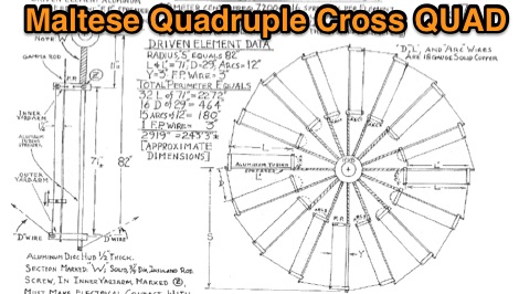 The Pfeiffer Maltese Quad Antenna System presents a unique approach to traditional quad antennas by utilizing a linear loading technique. This method effectively reduces the overall size of the antenna while maintaining its performance capabilities. Designed by Andrew Pfeiffer, the antenna's configuration resembles a Maltese cross, which not only enhances its structural integrity but also allows it to withstand challenging environmental conditions. This system is adaptable, offering various configurations from a 4-spreader Maltese Quad to a 16-spreader Maltese Quadruple-Cross, making it suitable for operators looking to optimize their setup without sacrificing efficiency. This antenna system is particularly versatile, covering multiple bands including 40, 20, 17, 12, and 10 meters. The design focuses on minimizing the physical footprint while ensuring effective signal transmission and reception. Amateur radio operators can benefit from the detailed plans available in the accompanying PDF, which outlines the construction process and specifications. Whether you're a seasoned DXer or a newcomer to the hobby, the Pfeiffer Maltese Quad Antenna System offers a practical solution for enhancing your station's capabilities.
 -
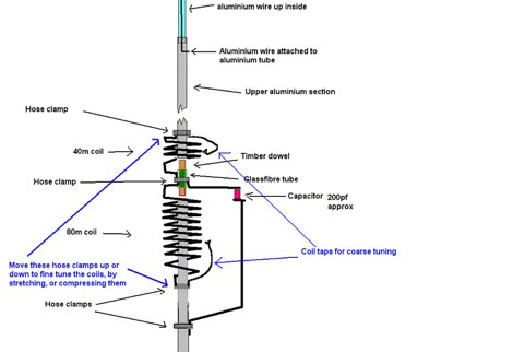 This is a custom home made antenna, based on concept of commercial HF antennas, that may work on 160 meters too.
 -
 The HB9ABX mobile HF antenna, developed by _Felix Meyer_, offers a high-performance alternative to commercial mobile antennas for 80 through 10 meters. Constructed from fiberglass rods and enamelled copper wire, this design incorporates a loading coil with multiple taps, allowing for band-specific tuning. The article provides detailed instructions for winding the coil, connecting the antenna elements, and integrating it with a vehicle's chassis ground. Field tests conducted at 100W consistently showed the HB9ABX antenna outperforming a HUSTLER mobile antenna by up to **10 dB** (1 S-point) and a YAESU ATAS-100/120 by **18 dB** (2-4 S-points) across distances from 5 km to 1000 km. The design emphasizes a robust ground connection and the use of an antenna tuner, such as an _MFJ-901B_, for optimal SWR on all bands, particularly 40 and 80 meters. Initial adjustment involves setting whip length and coil tap positions to achieve resonance without a tuner, followed by fine-tuning with the tuner during operation. Specific measurements are provided for checking resonance on 21.0 MHz and 14.2 MHz, with precise turn counts for the lower (79 turns) and upper (120 turns) antenna sections. Safety precautions for handling fiberglass dust are also highlighted.
 -
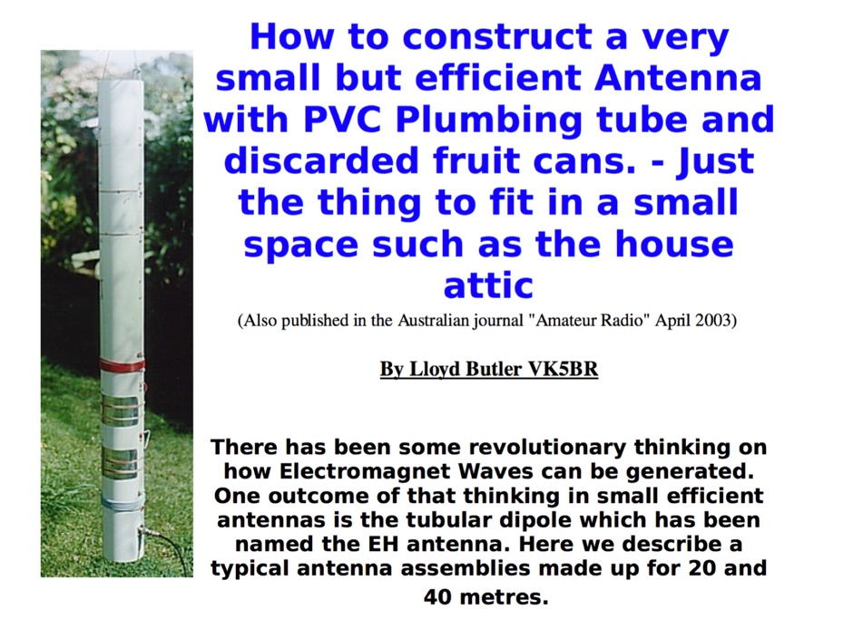 How to construct a very small but efficient Antenna with PVC Plumbing tube and discarded fruit cans. - Just the thing to fit in a small space such as the house attic
 -
 The page describes two types of 2 meter J-Pole antennas, one made of copper pipe and a roll-up J-pole made of TV twin lead, providing dimensions, components, and construction details. It is authored by Dr. Carl O. Jelinek N6VNG.
 -
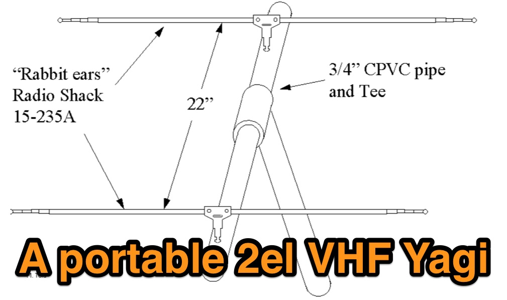 Build a portable VHF yagi antenna for 2 meters. All you need is two rabbit ear antennas from Radio Shack, two CATV baluns, four feet of 3/4 CPVC pipe with one tee.
 -
 The website https://www.qsl.net/dl5dbm showcases homebrew projects related to KW, 2-meter, 6-meter, antennas, amplifiers, preamps, power supplies, and more. It provides information and resources for radio amateurs interested in DIY projects and experimentation.
 -
 The RXO Unitenna, a vertical wideband antenna, offers operation across the 7-21 MHz spectrum, covering the 40, 30, 20, 17, and 15-meter amateur bands. This design focuses on achieving a low SWR across a broad frequency range, making it suitable for general HF operation without requiring an external antenna tuner for minor SWR variations. The antenna utilizes a unique loading coil and matching network to maintain efficient radiation characteristics across its operational bandwidth. Construction details within the PDF document include specific dimensions for the radiating element and the counterpoise system, which is critical for vertical antenna performance. The design incorporates readily available materials, simplifying the build process for radio amateurs. Performance graphs illustrate the SWR characteristics across the 7 MHz to 21 MHz range, demonstrating the antenna's wideband capabilities. The document also provides guidance on feedline connection and grounding considerations for optimal field deployment. This vertical antenna configuration is particularly useful for hams with limited space, offering a compact footprint compared to horizontal wire antennas.
 -

-
 NGC is now distributor for COMET and MALDOL brand antenna products designed, manufactured in Japan. Distributor of DAIWA brand RF SWR/power meters and switching power supplies, antennas, test equipment, antenna analyzers and more
 -
 How High should my Dipole be? Dipole Antennas and the effect of height above ground. The effectiveness of a dipole antenna is influenced by its height above ground, determined by the intended use such as DX work, local communication, directionality, omni-directionality, and feed point impedance. Through EZNEC modeling, the study evaluates a 40-meter dipole's performance at various heights, from 7 to 560 feet. Findings reveal that lower heights enhance omni-directional local communication, while higher placements favor DX work with low-angle radiation. The study emphasizes the importance of defining operational goals to optimize dipole height and performance.
 -
 Details the construction and optimization of antenna systems for amateur radio satellite operations, focusing on practical, homebrew solutions for VHF/UHF bands. It covers building _groundplane antennas_ from salvaged materials, recycling old beam antennas into new configurations like a 2-meter crossed yagi, and constructing a 10-meter horizontal delta loop. The resource also explains antenna matching techniques, including folded dipole driven elements and quarter-wave transformers, along with the importance of accurate SWR measurements and minimizing coax loss. Demonstrates how to achieve a **1:1 SWR** by carefully trimming elements and adjusting radial angles on groundplane antennas. It provides insights into selecting appropriate coax and connectors, highlighting the benefits of Belden 9913 for low loss and the proper installation of _N-connectors_. The article also addresses RFI mitigation from computer birdies and presents a design for a silent triac antenna control circuit, offering practical solutions for common satellite station challenges.
 -
 Demonstrates a **shunt-feed** matching technique for Hustler mobile HF antennas, specifically the MO-3 mast with RM series resonators, to achieve optimal **SWR** on the 40-meter and 20-meter bands. It details the construction of a loading coil using 20 turns of #12 solid wire, 1.25-inch ID, spread to 5 inches, and provides tap points: 8 turns for 40m and 4 turns for 20m, connecting one end to the feed point and the other to ground. The resource presents specific SWR results, noting a 1:1 match at 7.258 MHz on 40m and 14.275 MHz on 20m, with SWR remaining below 1.5:1 across significant portions of the General phone segments. It highlights a noticeable improvement in both transmit and receive performance compared to a straight antenna setup, emphasizing the practical application of this matching method for mobile installations, particularly on a fender-mounted ball mount.
 -
 An efficient program to calculate dimensions of coax dipoles, or bazooka antennas considering velocity length of different coax cables. Express dimensions in feet/inch and meters/cm. Freeware by VE3SQB
 -
 11 Meter CB, 10 Meter Amateur Ham, FRS, GMRS Radios, Test Meters, Scanners, Antennas, Microphones, Power Supplies, Inverters, Accessories and Technical Reference Information.
 -
 A 1.5-meter telescopic whip antenna project for the Yaesu FT-817 QRP transceiver is presented, offering a cost-effective alternative to commercial portable antennas like the Whip Miracle. The design incorporates a **toroidal matching unit** with a rotary switch for band selection and a toggle switch for fine-tuning the coil taps. This setup allows operators to achieve a low **Standing Wave Ratio (SWR)** across various HF bands, despite the inherent limitations of a physically short radiator on lower frequencies. The construction details include photographs of the completed unit, showcasing the compact enclosure and the integration with the FT-817. A simple schematic illustrates the coil tapping arrangement and the switching mechanism, guiding hams through the assembly process. The project emphasizes practical, portable operation for **QRP** enthusiasts, acknowledging that while performance on bands like 80m or 40m will be modest, it can still facilitate contacts under favorable conditions with skilled operation.
 -
 Quad Antennas by CUBEX, Cubex currently offers Cubical Quad antennas for 2 meters through 40 meters.
 -
 Normal mode helix antennas offer a solution for HF mobile operators facing significant height restrictions, such as those parking in indoor garages with limited overhead clearance. This design, adapted from concepts typically applied to VHF/UHF rubber duck antennas, allows for extremely shortened HF radiators that remain effective for county hunting and general mobile operation. The resource details the construction of a 20-meter helix antenna, approximately 10 inches long, wound with #14 AWG THHN wire on a 1 1/2-inch CPVC form, mounted on a standard 3/8 x 24 antenna stud. Mark Herson, _N2MH_, shares his experience developing these antennas, including initial research from the _RSGB VHF UHF Manual_ and practical winding experiments to establish the relationship between turns and resonant frequency. He provides coil data for various frequencies, emphasizing that these measurements were taken with an _MFJ-259a_ antenna analyzer and are dependent on the vehicle's grounding system. Despite their shortened nature, N2MH confirms the antennas' operational effectiveness, citing contacts with KL1V in Alaska on 20 meters and E-skip contacts on 10 meters. The design prioritizes continuous deployment without removal, making it suitable for operators who frequently navigate height-restricted environments.
 -
 Experimental omni-directional antennas for 6-meters band
 -
 Maco Manufacturing, HF Antennas, gamma matches, cable assemblies, power supply, swr meters, watt meters
 -
 Demonstrates the construction and on-air performance of the _NB6Zep_ antenna, a modified 20-meter Extended Double Zepp design optimized for multi-band operation from 40 through 10 meters. The resource covers basic design principles, including dimensions of 66 feet horizontal and 5 feet vertical elements, and specifies open ladder line or TV twin lead for the transmission line. It details material selection for low-cost wire antenna construction, such as 18 AWG wire for the legs and ceramic or plastic insulators, along with practical tips for soldering connections and insulating against moisture. The author, NB6Z, shares insights from extensive _EZNEC_ modeling to optimize the antenna's total length for a 40-meter half-wave dipole footprint and feed line length for direct tuner connection. The article presents field results, including successful _PSK31_ contacts from Oregon to the East Coast on 40 and 30 meters with 50 watts, even at a low height of 6 feet. It provides detailed performance characteristics for each band, noting the _NB6Zep_'s highest gain (over 3 dB) and sharp, medium-angle lobes on 20 meters, which yielded strong DX reports to locations like Korea, Japan, and Argentina. For 17 and 15 meters, it describes a butterfly-like pattern with broad lobes, while 12 and 10 meters exhibit narrow, directional lobes in an "X" configuration. The author also shares personal experiences operating successfully for over a decade in an antenna-restricted environment using the NB6Zep and other stealth wire antennas.
 -
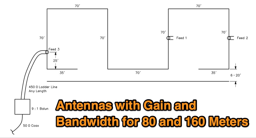 The Bruce array is a simple, often-forgotten wire antenna array that is advantageous for 80 and 160 meters, where typical gain antennas are very large. This bi-directional broadside vertical array is only 1\4 lambda high and does not require a ground system. It offers substantially greater SWR bandwidth than the half-square or bobtail curtain. A 4-element Bruce array used by N6LF showed a gain of about 4.6 dB compared to a 1\4 lambda vertical with 8 elevated radials, with a 2:1 SWR bandwidth greater than 400 kHz. The antenna is simple and its dimensions are flexible.
 -
 Lots of information of hidding transmitters, building portable yagi antennas, s-meters, and much more
 -
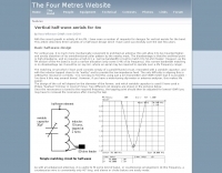 This project details three variants of a vertical half-wave antenna design for the 4-meter (70MHz) amateur radio band. The antennas use end-feeding with a parallel-tuned circuit for impedance matching to 50-ohm coaxial cable. The first variant uses suspended flexible wire for portable use, the second employs a fiberglass rod with internal wire for permanent outdoor installation, and the third utilizes aluminum tent poles for quick mobile deployment. Despite the narrow bandwidth of the matching circuit, this suits the narrow 4m FM allocation well. The design offers an effective omnidirectional radiation pattern and can be constructed with readily available materials.
 -
 The KD6WD Moxon Antenna Project details the construction of 50-ohm two-element wire beam antennas, specifically Moxon rectangles, for the 10, 15, 17, and 20-meter bands. It utilizes AC6LA's software for critical measurement calculations (A-E) based on center frequency and wire size. Construction involves 16-gauge silver-coated copper wire, 16-foot telescoping fiberglass crappie fishing poles as spreaders in an "X" configuration, and various hub designs including aluminum tubing or PVC joints. A 1:1 current balun is used at the feedpoint, with wire nuts for connections, often achieving a 1:1 SWR across the design band. The project highlights practical applications, such as running a kilowatt into the antennas for greyline DX contacts, consistently yielding excellent signal reports. Comparisons to quad loops show 4 to 5 S-unit improvements in both receive and transmit. The Moxon design, according to L.B. Cebik's analysis, offers superior forward gain and front-to-back ratio among wire beams. The author notes a "DX-Vane" effect where a freely suspended Moxon automatically points to the strongest DX signal. Attempts at dual-band operation (17/20 meters) with a single feed were unsuccessful, reinforcing the Moxon's monoband nature, with EZNEC plots provided for a 17-meter Moxon at 30 feet.
 -
 EI7BA Multiband Cubical Quads projects, includes two elements quad antennas for 10 12 15 17 20 meters band. Performance considerations, detailed pictures and construction notes.
 -
 WB2VUO presents a practical examination of effective HF mobile antennas, focusing on the inherent efficiency challenges encountered on the lower bands, specifically 160, 80, and 40 Meters. The resource delves into the necessity of loading coils for mobile operation below 21 MHz, where full-sized antennas are impractical. It contrasts base-loaded and center-loaded designs, noting that base-loaded antennas are simpler for the average ham to construct but offer lower efficiency compared to center-loaded configurations. The author provides specific data for an 8-foot whip, detailing its electrical length and _radiation resistance_ across various HF bands, from **0.08 ohms** on 160 Meters to **16.1 ohms** on 12 Meters. This data highlights the extremely low radiation resistance on lower frequencies, which significantly impacts feedpoint impedance due to ground and feedline losses. The discussion includes practical considerations for feedpoint impedance, noting that a typical 8-foot whip on 10 Meters might present 30-45 ohms, allowing for acceptable SWR without an ATU. Construction sketches illustrate both base-loaded and center-loaded mobile antennas, with advice on material selection like galvanized steel for rugged bottom sections. The article also includes coil value charts from the _ARRL Mobile Manual_ for both base and center loading, emphasizing the importance of using large diameter wire to minimize losses and suggesting capacity hats to reduce coil inductance and improve performance on 160-40 Meters.
 -
 Selecting an appropriate antenna system for shortwave broadcasting involves evaluating various types based on performance, cost, and operational parameters. This resource details the critical specifications for broadcast antennas, including average and peak power ratings, directivity, takeoff angle (TOA), horizontal beamwidth, and gain, emphasizing that a 100-kW transmitter requires an antenna rated for 150 kW average and 400 kW peak. It clarifies that low TOA signals travel thousands of kilometers, while high TOA is for local coverage, and nearly all modern shortwave broadcast antennas are horizontally polarized. The article explores specific antenna types, such as Log-Periodic Antennas (LPAs), which offer wide frequency ranges (e.g., 2-30 MHz) and directional patterns with 11 dBi gain, costing from $20K to over $100K for multi-curtain versions. Dipole arrays, also known as curtain antennas, are prevalent in international broadcasting, featuring steerable beams (±15° and ±30°) and mode-switching capabilities to alter TOA, with high/low pairs costing over $1 million. Fan dipoles are noted for omnidirectional patterns, smaller size, and lower cost for low-power applications, while rhombics, though simple, require resistive termination and incur several dB of I2R losses. Balun considerations are crucial, as most communications baluns are not rated for the higher average and peak powers of AM broadcast transmitters. Modern shortwave antennas utilize durable materials like Alumoweld wire rope for radiators and support elements, avoiding copper, fiberglass, or materials prone to stretching or deterioration. Feeder systems for high-power stations often require tapered-line baluns to convert 50-ohm unbalanced power to 300-ohm balanced for connection to the antenna.
 -
-
 Vertical antennas for all HF bands, expecially 80 40 20 meters bands
 -
 Rigid Dipole antennas for 14 MHz band using PVC and Aluminium tubing
 -
-
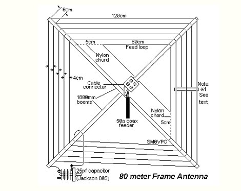
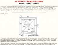 This projects was developed as a result of experiments to become QRV on 80 meters, again, using the little balcony by SM0VPO
 -
 Examines the practical considerations and technical challenges of deploying mobile antennas for 10-meter operation, particularly for operators on the move. It addresses the inherently _lossy_ nature of shortened, loaded vertical antennas typically used in mobile configurations, encouraging hams to view these limitations as engineering challenges. The resource provides actionable advice on safeguarding vehicle electronics, selecting appropriate cabling like _RG-213_, and properly grounding antenna mounts to the vehicle chassis. Specific mounting strategies are detailed, including roof, trunk lip, and side-mounting for trucks and vans, along with their respective advantages and drawbacks. It emphasizes the importance of a robust ground plane and suggests methods for improving grounding beyond simple set screws. The article also touches on antenna choices, mentioning "bugcatchers" and "Hamstick types" as viable options for 10 meters. Furthermore, the guide transitions to stationary mobile operation, where antenna options expand significantly. It outlines how to deploy portable dipoles or 2-element beams from a parked vehicle, offering practical tips for assembly, storage, and mast guying using simple materials like a concrete block. It notes that a 5/8 wavelength height, approximately **20 feet** on 10 meters, often yields good short-skip and DX performance, even with a take-off angle above **20 degrees**.
 -
 All copper J-Pole antennas for sale. 6 meter, 2 meter, 222 MHz, 440 MHz, LPFM, Marine, GMRS. Includes a construction plan in pdf format if you wish to build your own antenna.
 -
 The **NW3Z** optimized wideband antenna designs, originally presented at Dayton 2001, detail Yagi configurations for the 20-meter, 15-meter, and 10-meter amateur radio bands. This resource provides access to the design files, likely containing critical parameters such as element spacing, element lengths, and boom dimensions, which are essential for replicating these directional antennas. The designs focus on achieving wide bandwidth, a desirable characteristic for contesters and DXers operating across a significant portion of each band. The content specifically references "nw3z-Antenna-DesignsDownload," indicating that the core information is available as a downloadable file, presumably in a format suitable for antenna modeling software or direct construction. Such files typically include **NEC models** or similar data, allowing for performance analysis and optimization before physical construction. The emphasis on "optimized wideband" suggests design considerations for SWR bandwidth and gain characteristics over a broader frequency range than typical narrow-band Yagis. The resource serves as a direct source for specific, proven antenna designs from a known amateur radio antenna designer, offering practical data for hams interested in building high-performance Yagi arrays for HF.