Search results
Query: beam dx
Links: 57 | Categories: 0
-
 Details the construction of a **multiband vertical** antenna, specifically designed for stealth operation in a rented property, covering 80m, 60m, 40m, and 30m. The author, N3OX, leverages a 12m Spiderbeam telescoping fiberglass pole as the primary support, noting its sturdiness compared to typical fishing rods while remaining light enough for quick deployment and takedown. The radiating element is a 14 gauge Flex-Weave wire, attached to the pole's top with a rubber grommet, and fed by 27 bare 18 gauge radials spread across a 40-foot square backyard. N3OX describes the impedance matching solution, opting for custom-built L-networks over a remote tuner to enable fast bandswitching. Using an MFJ-259B and EZNEC modeling, base impedances were measured and component values calculated with G4FGQ's L_TUNER and SOLNOID_3 programs. The 80m coil is wound on a 3.5-inch PVC form, while the 30m, 40m, and 60m coils are air-wound, self-supporting #10 wire. Variable capacitors are incorporated for 40m and 30m shunt elements, with the 60m impedance matched by a series inductor. The project includes a **servo-controlled** homebrew band switch, utilizing a two-pole 12-position ceramic wafer switch for remote operation, addressing the limited 80m bandwidth. The entire matching network is housed in a weather-resistant shelter constructed from lumber and aluminum flashing. N3OX reports good DX results at 100W, estimating the total cost between $150 and $250, depending on existing parts.
 -
 For radio amateurs considering homebrew antenna projects, this resource details several designs from WE6W, an experienced operator. It covers the construction and characteristics of a _160 Meter QRP Loop Antenna_ optimized for high voltage, along with standard and folded variations of the double bazooka antenna. The site also presents a unique Field Day antenna design and instructions for building a Sterba Curtain, a directional array known for its gain. Each design includes practical insights from the author's building experience. The author provides comparative data, such as the performance of a standard bazooka against a traditional dipole, offering real-world context for antenna selection. The Sterba Curtain section includes notes on its beamwidth and gain, crucial parameters for directional operation. These designs are suitable for hams looking to experiment with cost-effective, high-performance antennas for various bands and operating scenarios, from QRP on 160m to directional DXing with a Sterba Curtain, which can offer significant forward gain, often exceeding **10 dB**.
 -
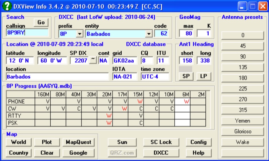 A free application that displays location information determined from a callsign, displays translations of common "QSO words and phrases" in the languages used in the callsign's DXCC entity, displays beam headings and SpotCollector DX Spots on a world map, displays country maps, and provides point-and-click control of antenna rotators from AlfaSpid, ARSWIN, Heath, Hygain, M2, Prosistel, SARTek, TIC, Trackbox, and Yaesu
 -
 G5RV 40m Beam Antenna. Adding a 28 ft. piece of vertical wire to one end of a 102 ft. center-fed dipole turns it into a 40m beam with a very wide beamwidth
 -
 The HB9ABX RoomCap antenna document details the construction and performance characteristics of a compact HF antenna design. It presents a series of comparative field tests conducted between July and September 2005, evaluating the HB9ABX antenna against established designs like the Microvert MV-500, Cushcraft R5/R7000 verticals, and a 5-element DJ2UT Yagi beam. Specific test scenarios include mobile installations, rooftop deployments, and comparisons on 20m, 40m, 80m, and 160m bands, with signal reports from various European and DX stations. The resource emphasizes the antenna's small physical footprint and its claimed efficiency across multiple HF bands. Test results consistently show the HB9ABX antenna performing comparably to, and often outperforming, larger reference antennas in terms of received signal strength, with reported differences of 1 to 2 S-points (6-12 dB) in many contacts. Notably, a 20m DX test on July 26, 2005, indicated the 1.3m HB9ABX radiator yielded 2-3 S-points stronger signals than an R7000 vertical for US DX stations. An August 12, 2005, test on 40m highlighted the HB9ABX's superior signal-to-noise ratio in urban QRM, demonstrating 10-18 dB better performance than an R7000. The document includes specific callsigns, signal reports, and QTHs for each comparison, providing empirical data for the antenna's performance claims.
 -
 The Shunt-fed Tower, an effective Low Band Antenna, uses your beam as a capacitive top-hat and only needs a simple feed network and a good ground system to work DX on 80M and 160M.
 -
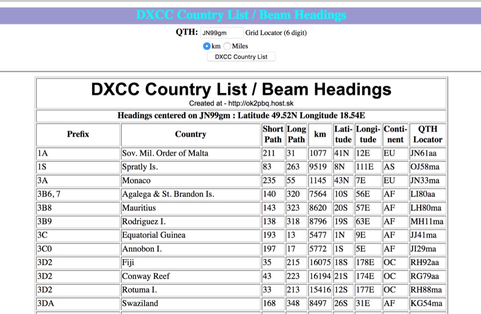 You can have your persolal DXCC country list with correct beam heading calculated on you grid square location
 -
 HF Vertical and Beam Antennas, antennas accessories by Butternut. Bencher is out ouf ham radio business. Recently company products has been sold to Vibroplex and DX Engenieering.
 -
 The KD6WD Moxon Antenna Project details the construction of 50-ohm two-element wire beam antennas, specifically Moxon rectangles, for the 10, 15, 17, and 20-meter bands. It utilizes AC6LA's software for critical measurement calculations (A-E) based on center frequency and wire size. Construction involves 16-gauge silver-coated copper wire, 16-foot telescoping fiberglass crappie fishing poles as spreaders in an "X" configuration, and various hub designs including aluminum tubing or PVC joints. A 1:1 current balun is used at the feedpoint, with wire nuts for connections, often achieving a 1:1 SWR across the design band. The project highlights practical applications, such as running a kilowatt into the antennas for greyline DX contacts, consistently yielding excellent signal reports. Comparisons to quad loops show 4 to 5 S-unit improvements in both receive and transmit. The Moxon design, according to L.B. Cebik's analysis, offers superior forward gain and front-to-back ratio among wire beams. The author notes a "DX-Vane" effect where a freely suspended Moxon automatically points to the strongest DX signal. Attempts at dual-band operation (17/20 meters) with a single feed were unsuccessful, reinforcing the Moxon's monoband nature, with EZNEC plots provided for a 17-meter Moxon at 30 feet.
 -
 A 70 MHz Moxon rectangle antenna, built with 0.83mm enamelled copper wire and a lightweight fiberglass kite spar frame, offers a compact two-element beam solution for the 4-meter band. This design, originally for HF, scales effectively to VHF, reducing the antenna's width to approximately 75% of a half-wavelength while allowing direct coaxial cable feeding. The author, G6GVI, details the construction process, including the use of an automated design tool for precise dimensions. Initial field testing revealed a VSWR of approximately 1.3, with distinct nulls observed at 90 degrees when the antenna was mounted horizontally. The lightweight build, supported by a wooden block and U-bolt for mast attachment, makes it suitable for thinner mast sections. Further experimentation included testing with vertical polarization and considering its potential for indoor loft installation due to its relatively short major axis, offering a discreet option for urban hams.
 -
 Examines the practical considerations and technical challenges of deploying mobile antennas for 10-meter operation, particularly for operators on the move. It addresses the inherently _lossy_ nature of shortened, loaded vertical antennas typically used in mobile configurations, encouraging hams to view these limitations as engineering challenges. The resource provides actionable advice on safeguarding vehicle electronics, selecting appropriate cabling like _RG-213_, and properly grounding antenna mounts to the vehicle chassis. Specific mounting strategies are detailed, including roof, trunk lip, and side-mounting for trucks and vans, along with their respective advantages and drawbacks. It emphasizes the importance of a robust ground plane and suggests methods for improving grounding beyond simple set screws. The article also touches on antenna choices, mentioning "bugcatchers" and "Hamstick types" as viable options for 10 meters. Furthermore, the guide transitions to stationary mobile operation, where antenna options expand significantly. It outlines how to deploy portable dipoles or 2-element beams from a parked vehicle, offering practical tips for assembly, storage, and mast guying using simple materials like a concrete block. It notes that a 5/8 wavelength height, approximately **20 feet** on 10 meters, often yields good short-skip and DX performance, even with a take-off angle above **20 degrees**.
 -
 The AZIMUTH program plots a world map in either azimuth (beam heading) or Mercator projections. If you specify your home location in latitude and longitude, the azimuth projection is centred on your location. The Azimuth map program can display Maidenhead grids - this is useful for 6m, 2m, and UHF DX communication display. Various features of the map are: Azimuth or Mercator projections , Maidenhead grid display, Simple map zooming, Print maps with adequate resolution up to one meter sized map
 -
 For amateur radio operators seeking a compact, directional antenna for the 10-meter band, this resource details the construction of a Moxon Yagi beam. The design utilizes readily available PVC pipe for the boom and elements, with specific measurements derived from the Moxon Rectangle Generator software. It outlines the assembly process for the main boom and end sections, providing critical dimensions for element spacing and overall length to achieve resonance at 28 MHz. The Moxon configuration offers a smaller footprint compared to a traditional Yagi, making it suitable for limited space installations. The article provides practical guidance for hams interested in a DIY antenna project, emphasizing the use of common hardware store materials. It specifies a 1 1/4" PVC schedule 40 pipe for the main boom and details the use of tees, reducing bushings, and 45-degree elbows for the element ends. Key measurements like the 55" spacing for the ends and the 150 3/4" overall length are provided, enabling replication of the design. The Moxon's inherent wide beamwidth and good front-to-back ratio make it an effective choice for DXing on 10 meters.
 -
 The W8JK is a famous and effective DX antenna, first built by John Kraus, W8JK, in 1937. A Beam antenna with two parallel dipoles driven with opposite phase, with a close spacing of an eighth of a wavelength.
 -
 Over 70 international contests are supported by YPlog, a Windows-based logging and radio control program designed for amateur radio operators. This software integrates with various digital mode applications like _WinPSK_, _HamScope_, and _MMTTY_, facilitating partially automated log entry for modes such as PSK31, CW, and RTTY. It provides comprehensive logging capabilities including QSL label printing, beam headings, and dup-checking, alongside award tracking for DXCC, ITU/CQ zones, IOTA, Grid Locators, and Counties. The program offers advanced contesting features, including multi-multi or multi-2 networked operations with automatic log data sharing, multiple Cabrillo submission formats, and configurable CW keyboard layouts. Device support extends to TR-compatible CW keying, SO2R control with Top-Ten devices like the DX-DOUBLER, and internal W9XT digital voice keyer integration. YPlog is notable for its support of the _OK1RR DXCC_ country resolution files, providing a robust historical DX compendium. Beyond logging, YPlog includes two freeware utilities: one for computing design parameters for coaxial traps and another for displaying and printing azimuth and Mercator maps from the operator's QTH. The software runs on Windows 95/98/ME/NT/2K, with a recommended screen resolution of 1024x768. Registration costs **$50.00 US** to unlock all features, including full contesting capabilities and rotator control.
 -
 An experimental antenna, similar to the _TAK spiral antenna_, was evaluated for SWR response over the 7.0 to 7.3 MHz frequency range. The analysis presents specific results: beam length significantly affects SWR, with increased distance between spirals raising the resonant frequency; the combined length of antenna and hookup wire lowers the resonant frequency as it increases; and spiral diameter impacts bandwidth, with larger diameters yielding greater bandwidth. The design addresses the fixed beam length limitation of the commercial TAK antenna by introducing an adjustable version constructed primarily from PVC electrical conduit and water pipe, using 14-gauge aluminum wire. The resource includes a detailed mechanical design, construction steps, and a parts list. It also features a spiral antenna spreadsheet model for calculating design parameters like start point, pitch, safe edge, spoke length, and arm length, which aids in determining wire length and kerf cutting tables. Model verification involved constructing an antenna to specific parameters, with SWR tests conducted using an _MFJ Model 269_ antenna analyzer at 13 feet above ground with 60 feet of RG8 mini coax. Measurements showed that adjusting beam length from 27 to 37 inches shifted the resonant frequency by approximately 0.18 MHz. Further data compares 32-inch versus 48-inch diameter spirals, demonstrating increased bandwidth for the larger diameter. The model accurately predicted revolutions for given antenna lengths, pitch, and starting distances. The final design achieved a resonant frequency of 7.17 MHz, favoring the voice portion of the 40-meter band after adjustments.
 -
 The document details the optimization and construction of the _Maria Maluca_ antenna, a compact 6-band (20m-6m) directional beam. It presents a comparative analysis of shortwave antenna principles, highlighting the efficiency gains achieved by using an open feeder line and tuner as a resonant unit, contrasting this with the losses associated with traps or capacitive loads in multiband antennas. The resource specifically revisits an older South American 2-element design for 10, 15, and 20 meters, applying modern NEC-based software to develop a six-band version. Performance data is meticulously tabulated, showing impedance, free space gain, gain at 12m height, elevation angle, and front-to-back (F/B) ratio for each band from 20m through 6m. For instance, on 15m, the antenna achieves 5.1 dBd free space gain and 13.72 dB F/B ratio. The construction section provides practical guidance on element assembly using aluminum pipes and hose clamps, detailing the use of a heavy-duty glass fiber reinforced polyamide rod for electrical separation and bending strength. It also specifies the use of 450-ohm _Wireman_ line CQ 552 for the transmission line. The document includes diagrams for rod fixing, an air-wound balun, and a vertical elevation diagram for the 15m band, illustrating its DX qualification. It also discusses the antenna's suitability for portable and expedition operations, noting its compact transport dimensions (max 1.50m length, 12 lb weight) and quick assembly time (under 15 minutes). The author, Dipl.Ing. Helmut Oeller, DC6NY, is identified as a source for material kits.
 -
 This resource presents a technical guide detailing antenna measurement theory, focusing on the fundamental electromagnetic principles governing antenna operation and characterization. It delineates the three primary spatial regions surrounding an antenna: the reactive field (0 < r < lambda/2pi), the radiating near-field (lambda/2pi < r < 2D2/lambda), and the radiating far-field (r > **2D2/lambda**). The guide defines key antenna parameters, including polarization, input impedance, VSWR, directivity, gain, efficiency, Effective Isotropically Radiated Power (EIRP), antenna noise temperature, and the G/T parameter. Radiation patterns are discussed, with examples of both rectangular and polar forms, emphasizing the determination of patterns in the far-field region for constant radial distance and frequency, typically characterized by a main beam with **3 dB** beamwidth and sidelobes. The document further elaborates on the mathematical definitions of these parameters, such as the Poynting vector (E x H*) for electromagnetic waves and the relationship between antenna gain and directivity. It also introduces related terms like mixers, which are critical components in antenna measurement instrumentation for frequency conversion (fIF = fRF +/-nfLO). The theoretical framework provided supports the scientific analysis of antenna performance, applicable to various antenna types and operational frequencies. DXZone Focus: Technical Guide | Electromagnetic Theory | Far-Field Region | G/T Parameter
 -
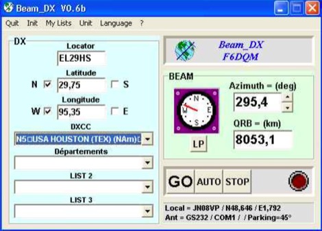 BEAM_DX is a free windows software for radioamateurs or radio listeners usage. It allows to point a directionnal antenna towards an azimuth, a locator, an international prefix or any other geographical position on earth predefined by its latitude and its longitude
 -
 JJ0DRC's HF multi-band delta loop antenna project, initially conceived during the waning peak of Cycle 23, addresses the common challenge of achieving effective DX operation from a small residential lot in Japan. Dissatisfied with a ground plane antenna's performance in SSB pile-ups, the author sought a beam-like solution without a tower, drawing inspiration from a JJ1VKL article in CQ Ham Radio Sep. 2000. The antenna, constructed in October 2000, employs two 7.2-meter fishing rods (37% carbon fiber, reinforced with cyano-acrylate glue and aluminum tape) and 1mm enameled wire, fed by an Icom AH-4 external antenna tuner. While the exact beam pattern remains unmeasured, JJ0DRC observed a significantly higher callback rate compared to dipole antennas, particularly on higher bands. The system's circumference length of 15-20m is crucial for maintaining a good beam pattern across HF bands, though performance on lower bands like 80m, 40m, and 30m becomes less directional as the length deviates from a full wavelength. Ongoing maintenance addressed degradation issues, including aluminum tape cracking and wire breakage at connection points due to strong winds (often exceeding 10-15m/s in winter). The author reinforced rod connections with IRECTOR PIPE SYSTEM components and INSU-ROCK ties, and improved wire attachment methods using Cremona rope and epoxy bond to enhance durability.
 -
 Illustrates the construction of a compact _Moxon_ beam antenna specifically tailored for the 40-meter band (7 MHz). The resource details a homebrew project by W7XA, emphasizing its design for limited space while maintaining good bandwidth and directivity characteristics. It highlights the practical application of the _Moxon_ rectangle model to achieve performance on a lower HF band. The primary content is a downloadable PDF document titled "40-Meter-Mini-MOXON-Beam-Antenna.pdf," which provides comprehensive illustrations and technical specifications for replicating the antenna. This includes dimensions, materials, and assembly instructions, making it a practical guide for radio amateurs interested in directional antennas for HF. The project demonstrates how a relatively small footprint can yield a directional antenna suitable for DXing or contesting on 40 meters, a band typically requiring much larger arrays for similar gain and front-to-back ratios. The documentation supports hands-on construction.
 -
 Located in France, DXBeam designs and manufactures a range of monoband, dual band and triband antennas, rotary dipoles, Moxons and Yagis
 -
 Details the construction of a **17-meter Moxon Rectangle** antenna, specifically engineered for mounting on a mast beneath an existing beam. The design incorporates insulated wire calculations (0.95804 x generator length) to compensate for velocity factor differences, utilizing readily available materials such as crappie poles for elements, PVC for the boom and mast, and a Budwig HQ-1 dipole connector for the 50 Ohm coax feed. The project outlines a step-by-step assembly process, including mast construction from PVC T-connectors and pipe, element fabrication from crappie poles, and securing elements to prevent droop. Initial testing demonstrated an SWR of 1.3:1 on 17 meters, achieving a 5-8 signal report into Texas with 100 watts. Subsequent reinforcement and elevation of the antenna resulted in a 15 over 9 report from Florida. Comparative testing against an 88-foot center-fed Zepp antenna indicated superior performance, with the Moxon consistently outperforming the Zepp and receiving signals the Zepp could not. A notable DX contact with JA8NFV in Hokkaido, Japan, yielded a 5-9+ signal report both ways using 100 watts.
 -

-
 Presents the mechanical and electrical specifications for a 5-element Yagi beam antenna designed for the 6-meter band. The resource details element lengths, spacing, and boom dimensions, specifically utilizing _EMT conduit_ for construction. It includes a diagram illustrating the element layout, a coaxial balun connection, and a reported SWR curve, providing a practical blueprint for hams to replicate the design. The design achieves a reported SWR of **1.1:1** at 50.125 MHz, indicating efficient impedance matching across the primary 6-meter DX window. The boom length is specified at 2.44 meters (8 feet), with element lengths ranging from 2.87 meters for the reflector to 2.59 meters for the director 3. This configuration suggests a gain figure typical for a 5-element Yagi, likely in the range of **9-10 dBi**, making it suitable for local and sporadic-E DX contacts.
 -
 Draws a world map centered on your QTH. Type in a DX station's call sign to get the beam aim azimuth and distance to the station.
 -
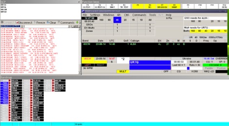 TR4W is a contest logging software package supporting over **180** amateur radio contests. The program operates on Windows 7 to windows 11 operating systems. It supports CW keying via serial port, LPT port, or Winkey, with CW speeds ranging from 1 to **99** WPM. Paddle input via LPT port enables the program to function as a keyer, with paddle input aborting computer-generated CW. PTT support includes programmable delay. The software incorporates automatic super check partial and call checking, along with an expanded .DTA database format for names, QTH, grid, and SS check information. A band map displays color-coded aging data. The software features a built-in telnet DXCluster interface, automatically inserting spots into the band map. It supports RTTY operation via the MMTTY engine and includes WAE QTC support for both European and non-European stations. TR4W provides radio interfacing for Elecraft, Icom, Japan Radio, Kenwood, Ten-Tec, and Yaesu transceivers, utilizing serial or USB-to-serial adapters. Networked multiple-rig operation is supported through a client-server model using TCP/IP protocol. Integrated two-radio support (SO2R) is present. The program includes on-the-fly MP3 recording and log backup to USB drives or selected HDD folders. It uses the standard CTY.DAT file for country and beam heading data.
 -
 Demonstrates the design and construction of a compact, portable multi-band mini-delta loop antenna, specifically optimized for /P (portable) operations from remote locations like Scottish islands. The resource covers the theoretical underpinnings of half-wave loops, contrasting closed and open configurations, and then details the application of a folded dipole principle to achieve a 50-ohm match for direct coax feed. It presents empirical formulas for calculating element lengths, considering the velocity factor of common wire types, and provides a detailed example for a 20m (14.175 MHz) version. The article includes a comprehensive table of dimensions and allowances for a five-band (20m, 17m, 15m, 12m, 10m) mini-delta beam, along with construction hints for the central support and balun. It specifies a 1:1 trifilar balun wound on a ferrite rod and describes the antenna adjustment process using an _MFJ-259B Antenna Analyser_. Initial test results indicate an SWR of 1:1 at resonance and a bandwidth of approximately 240 kHz on 20m, even at a low height of five feet above ground. The distinctive utility lies in its focus on a practical, easily deployable beam antenna for portable DXing, offering a viable alternative to more complex or larger arrays.
 -
 Description of the 80m antenna used at CN2WW in the ARRL-DX CW 2007
 -
 Over 47 full-screen maps are available within _NAOMI_ (North American Overlay Mapper), a free Windows program designed for US and Canadian amateur radio enthusiasts. This mapping suite includes 9 backgrounds such as CQ Zones, ITU Zones, and ARRL Sections, along with 16 foreground layers like Counties, Areacodes, and Grid Locators. Users can calculate distances and bearings, track real-time mouse positions with continuous Grid-Locator data, and integrate with APRS for live station tracking via the FindU database. For a global perspective, the _Global Overlay Mapper_ (GOM) provides a world map, 8 continental maps, and 29 sub-continental maps, all with 12 active layers including Country Outlines, CQ/ITU Zones, and Prefix information. Both NAOMI and GOM offer feature-locate systems to jump to positions based on prefixes, capital cities, or Grid Locators, and provide customized beam headings and distance displays. The site also features _LogView_, a post-contest log visualization tool that analyzes Cabrillo-format logs by plotting QSOs on maps, supporting over 30 major contests like CQWW and ARRL DX, and allowing comparison with published results.
 -
 The GW3YDX Super Moxon antenna design improves upon the standard Moxon Rectangle by incorporating additional directors in a rectangular configuration, yielding enhanced directivity and gain. For the 6m version, modeling with 4NEC2 and EZNEC+ indicated a 3dB gain increase and a 26.5dB front-to-back ratio, with VSWR below 1.5:1 between 50.0 and 50.3MHz when optimized for 50.1MHz. This design achieves a narrower -3dB power point beamwidth of 60° compared to the original Moxon's 80°, contributing to better QRM rejection. The boom length for the enhanced design is just under 2m, approximately double the original Moxon's, with no increase in wingspan. Construction details include tubing lengths for 6m, 4m, and 2m versions, with specific dimensions provided for elements A through M, measured to tubing centers. For instance, the 6m version uses a 2160mm element A and a 2140mm element H. The design maintains a 50-ohm feed impedance, with practical models showing VSWR plots consistent with simulations after minor adjustments to driven element lengths. The article also references Moxgen software for initial Moxon parameter calculation and NEC/EZNEC model generation. The 2m Super Moxon version measures approximately 30" x 25", demonstrating the compact nature of the design across different VHF bands. The article highlights the antenna's performance in real-world DX contacts on 6m, achieving contacts with over 80 stations in the USA from a modest QTH.
 -
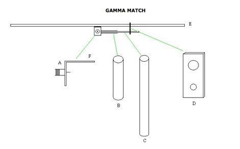 how to make a gamma match for a antenna. The Gamma match is the most used matching device used for yagi beams.
 -
 Constructing a compact, single-feed triband Moxon antenna for 20, 15, and 10 meters is detailed by DU1RZ, drawing from his personal experience with space-constrained antenna projects. Initially fascinated by cubical quads, the author transitioned to Moxon designs in 2005 after realizing his roof space was insufficient for a bulky quad. His first experimental monoband Moxon for 15 meters, built from repurposed materials, provided solid DX QSOs for seven years, despite being slightly below the 21 MHz band center. The project outlines the design process, including using the _MOXGEN Calculator_ for element dimensions and material selection, such as #14 AWG enamel copper wire and fishing poles for spreaders. DU1RZ shares insights from simulations with DL2GMS regarding insulated versus non-insulated wire performance, noting that insulated wire can shift resonant frequencies lower. The assembly instructions cover preparing wire elements, connecting feed points, and tuning the antenna, with initial SWR measurements taken at 10 feet and final readings on a mast showing excellent results: 1.0:1 on 14.225 MHz, 1.1:1 on 21.250 MHz, and 1.3:1 on 28.50 MHz. Transmission tests with 4F1BYN indicated a front-to-back ratio of approximately 2 S units with 10 watts output. The author emphasizes adaptability, encouraging builders to use readily available materials rather than strictly replicating his setup. Key observations from DU1RZ and DL2GMS highlight the antenna's strong performance across 20, 15, and 10 meters, good front-to-back ratio, full bandwidth on 20 and 15 meters, and its small turning radius of about 4.18 meters (13.54 feet), making it suitable for limited antenna space. Its lightweight construction and low wind load are also noted as significant advantages.
 -
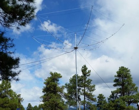
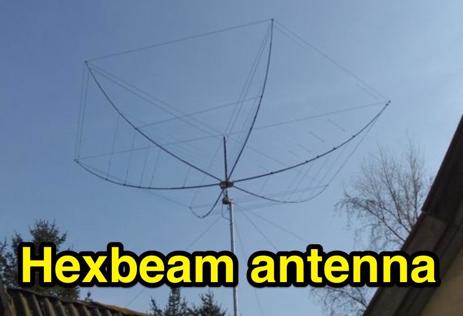 An HexBeam antenna project, a 2 full elements on six bands
 -
 This resource details the construction of a Moxon rectangle antenna, a two-element wire beam, drawing inspiration from a _QST_ article by Allen Baker, KG4JJH, and a project group led by KD6WD. It outlines the use of _AC6LA_ software for critical measurements (A-E) to design the antenna for specific bands like 17 meters, emphasizing the simplicity of adjusting frequency and wire size. The guide covers material selection for spreaders, such as telescoping fiberglass fishing poles, and various hub constructions, including aluminum tubing and PVC joints, with accompanying images. The author shares practical insights from building multiple Moxons for 10, 15, 17, and 20 meters, noting consistent 1:1 SWR at design frequencies and broadbanded performance. It describes the feedpoint assembly using a 1:1 Yagi current balun and wire nuts for robust, adjustable connections. The resource also discusses element insulators made from Lucite strips and attachment methods to spreaders using plastic wire ties and duct tape, ensuring precise element spacing. Performance observations include significant signal improvements (4-5 S units) over quad loops and a unique "DX-Vane" effect where the suspended antenna self-aligns with the strongest DX signal. The author also recounts an unsuccessful attempt at a dual-band 17/20 meter Moxon, concluding that the Moxon is inherently a monoband antenna, supported by _EZNEC_ plots for a 17-meter design.
 -
 A 2x3-foot laminated world map product is detailed, offering customization for amateur radio operators. Each map features two distinct views: one centered on the operator's specific station location and another precisely centered on its _antipode_. Countries are clearly labeled, complemented by a tabular listing of all countries. The map integrates a standard latitude/longitude grid alongside concentric circles that delineate distance increments radiating outward from the operator's QTH. Personalization includes the operator's name, callsign, and location printed directly on the map. This custom mapping service provides a unique visual aid for DXing and propagation analysis, allowing operators to quickly ascertain beam headings and distances from their station. The dual-view presentation, particularly the antipodal centering, offers a practical reference for understanding long-path propagation and identifying potential DX opportunities. The inclusion of distance circles and personalized station data makes it a tailored tool for daily operating and contest planning, distinct from generic world maps.
 -
 Constructing a compact directional antenna for the 17-meter band, this resource details the build process for a Moxon rectangle, a two-element Yagi variant with folded-back elements. It covers the antenna's evolution from the _VK2ABQ beam_ and provides specific dimensions for a version built using fishing pole whips. The content includes a discussion of the antenna's radiation pattern, feedpoint impedance, and its inherent front-to-back ratio, which is often superior to a standard two-element Yagi. Practical considerations for element spacing and material choices are also addressed, alongside a visual representation of the antenna's physical layout. Performance data presented includes a comparison showing the Moxon rectangle's **2.5 dB gain** over a half-wave dipole and a front-to-back ratio of **20 dB**. The resource also touches upon the antenna's relatively wide bandwidth for a two-element beam and its suitability for portable operations due to its compact footprint. It offers insights into optimizing the design for specific operating conditions and discusses the advantages of its lower take-off angle compared to omnidirectional wire antennas, making it effective for DX contacts on the 17-meter band.
 -
-
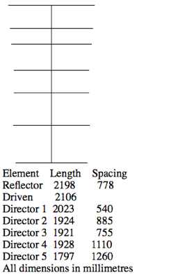
 Plans for building your own 3-element beam for use on 6m.
 -
-
 Designing and constructing a two-element receiving loop antenna array for HF operation involves specific considerations for achieving high directivity and noise reduction. This resource details a homebrew system comprising two 30-inch diamond-shaped loops, spaced 20 feet apart, which are fed through mast-mounted preamplifiers and passive signal combiners. The operational principle relies on adjusting phase delays between elements via precise _Belden 8241_ coaxial cable lengths, optimized for specific bands from 160m to 20m. Performance data, derived from _EZ-NEC_ modeling, illustrates consistent 90° azimuth-plane beamwidth and low take-off angles across the target bands, with _Receiving Directivity Factor_ (RDF) values comparable to a 300-foot Beverage antenna. The article presents detailed elevation and azimuth plots for 20m, 30m, 40m, 80m, and 160m, demonstrating the array's ability to provide strong response at low DX angles while also supporting _NVIS_ signals. Key components like the _DX Engineering RPA-1_ preamplifier and _DXE RSC-2_ signal combiner are discussed, alongside the importance of impedance matching to preserve antenna patterns. The construction emphasizes self-contained elements that do not require ground radials, offering a compact solution suitable for suburban environments and stealth installations, with a focus on optimizing receive performance independently from transmit antennas.
 -
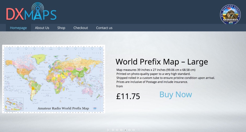 DX Maps provides a specialized map printing service, focusing on amateur radio applications such as world prefix maps and custom great circle projections. The platform allows radio operators to visualize propagation paths and DX entities relevant to their QTH and operational goals. This service supports the creation of high-quality, large-format maps tailored for shack display or operational planning. The service facilitates the generation of personalized maps, which can include specific callsign locations, beam headings, and other critical amateur radio data points. Users can specify parameters to create maps that aid in understanding global propagation conditions and optimizing antenna aiming for long-distance contacts. The UK-based operation ensures a localized service for European hams, with international shipping options available. DX Maps also offers QSL card printing, complementing its mapping services.
 -
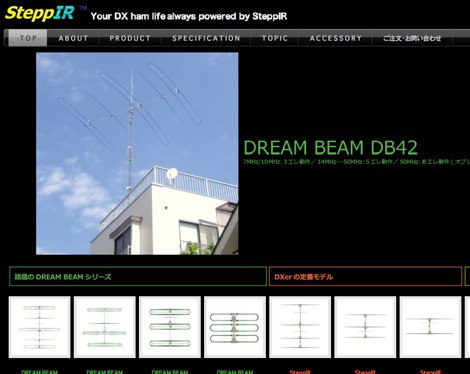 Presents _Beam Quest_, the official Japanese distributor for _SteppIR_ antennas, detailing their product lineup and services. The site showcases various _SteppIR_ Yagi models, including the _Dream Beam_ series (DB42, DB36, DB18E, DB11) with configurations from two to four elements, alongside the _Big IR_ and _Small IR_ vertical antennas. It also lists accessories such as TX/RX and PC interfaces, essential for integrating these advanced antenna systems into a ham shack. Operators often seek out _SteppIR_ antennas for their dynamically adjustable element lengths, which allow for optimization across multiple bands, a significant advantage for DXing and contesting. This adaptability contrasts sharply with fixed-element Yagis, providing a distinct edge in varying band conditions. The resource provides contact information, including email and phone numbers, for inquiries and support regarding _SteppIR_ products within Japan, serving as a direct point of contact for sales and technical assistance.
 -
 Documents S21RC's construction of an impedance transformer harness for a VHF/UHF cross yagi, utilizing 20m of _RG179_ cable. Details the creation of a DIY RF sampler with a -50dB sampling output, primarily for measuring HF radio PA section output with a Spectrum Analyzer, also applicable for _Pure Signal_ transmission. Chronicles the deployment of a 200m long beverage antenna for the _S21DX IOTA_ operation in 2022, positioned 2m above ground. Discusses the construction of a 3-element short beam for 10m to replace a previous 2-element antenna, with assistance from S21DW. Provides guidance on operating cheap _PA-70_ and _PA-100_ type Chinese SSPAs using IRF530 MOSFETs, emphasizing the necessity of a final LPF. Outlines the design and construction of a fully isolated interface for radio-to-computer connections, supporting various digital modes with isolated ground, audio transformers for IN/OUT, optical isolation for CAT/CIV, and isolated PTT/COS lines. Includes a log of software updates, such as the _HMI/TFT for NX8048K070_ and _2.1.14 Lite_ release with bug fixes for PEP hold and gradual watt decay.
 -
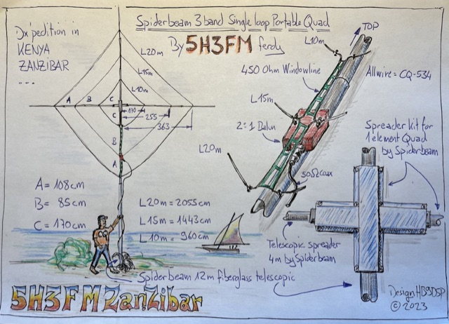 Handmade drawing of a 3 bands single loop, portable quad antenna used by the author during his dx pedition in Kenya as 5H3FM. This antenna is done using 3 telescopic spreaders and the spreader kit for 1 element quad by spiderbeam.
 -
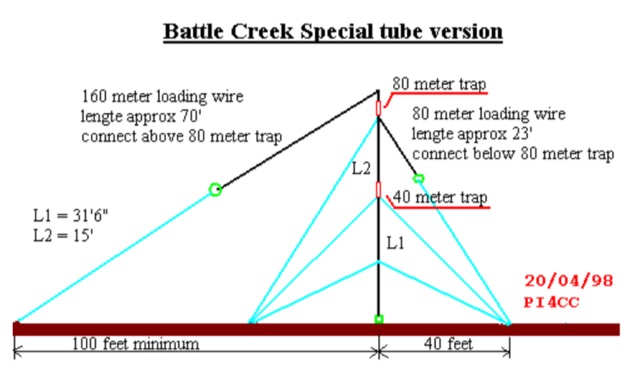 This antenna is designed for 40, 80 and 160 meters to complement a tri-band beam normally taken on DX peditions for 10, 15 and 20 meters, so six bands can be worked with only two antennas.
 -
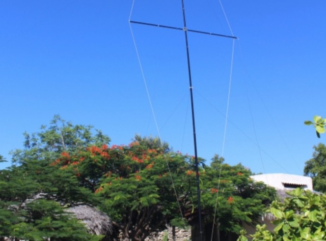 This project documents the construction and enhancement of a 30m Vertical Dipole Array (VDA) antenna inspired by Remco 7QNL article. Initial design utilized an 18m Spiderbeam pole and a 4m boom. Improvements included a lighter boom structure using fishing rods and a revised coaxial arrangement for enhanced mechanical stability.
 -
 Documents the design and construction of a **four-band Moxon beam** antenna, covering 20, 15, 10, and 6 meters. Author W7JMP shares his journey from initial research and computer modeling using 4NEC2 to the final on-air testing and optimization. The project aimed for gain over a dipole on 20 meters, with a budget under $500, including the antenna rotor. The design incorporates fiberglass spreaders and a single feedpoint, avoiding complex relay switching. The article details the selection of materials, assembly techniques, and the critical tuning process. W7JMP describes fabricating the hub, mounting spreaders, and attaching elements made from stripped THTN wire. A notable innovation is the use of a half-wave tuning stub with a loading coil for in-situ adjustment of the 20-meter reflector, optimized via remote S-meter readings using a webcam and smartphone. This method allowed for fine-tuning the **front-to-back ratio** without lowering the antenna. Initial testing revealed a dipole-like pattern, which was significantly improved after tuning, resulting in reported 2 to 4 S-unit front-to-back ratios and enhanced signal strength for DX contacts on multiple bands, including sporadic E on 10 and 6 meters.
 -
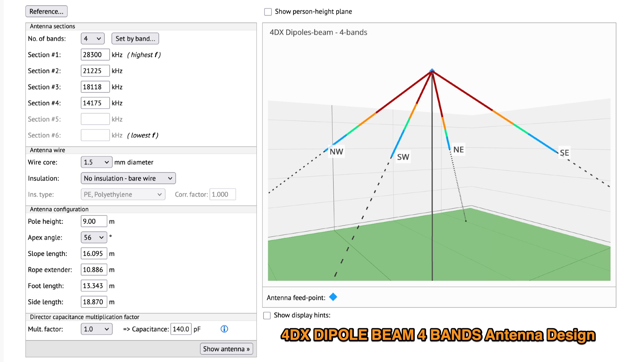 This page provides detailed information on the 4DX directional wire beam antenna designed by LZ1AQ, LZ1ABC, VK6LW, and DD5LP. It explains how to create this antenna for single or multiple bands using four separate sloping wires. The page includes instructions on achieving directionality, gains, and F/B ratios, as well as generating radiation patterns, VSWR charts, antenna currents diagrams, and Smith charts. It is a valuable resource for hams interested in building and optimizing their own directional wire beam antennas for improved performance and long-distance contacts.
 -
 Learn how to design a Hentenna antenna, a portable asymmetrical double-loop antenna ideal for amateur HF or VHF bands. This page provides details on constructing and optimizing the antenna for maximum performance in DX communications. Discover how altering the antenna's vertical feed section can adjust the VSWR resonant frequency and how changing the support pole's position can alter the beam direction. Originally developed by Japanese 6-meter operators, the 'Hentenna' offers a unique design that allows for horizontal polarization when vertically oriented. Explore radiation patterns, VSWR charts, and antenna currents diagrams to optimize your antenna's performance for long-distance contacts.