Search results
Query: google com ig
Links: 385 | Categories: 0
-
 Superfast analyzer for audio and radio signals. Examining radio signals is the original idea of Analyzer2000. Simply connect the AF-output of your receiver to the input of your soundcard and see, what you hear. Use SSB and you will have a feeling like using an expensive IF panorama adapter. Support for this version has been discontinued.
 -
 Dissects the internal components of the popular _Antron 99_ vertical antenna, revealing its unique design elements. The analysis details the construction of the coaxial phasing sections, which contribute to its multi-band performance across 10, 12, 15, and 17 meters. Observations include the use of fiberglass tubing for weather protection and the specific arrangement of conductors within the antenna's structure. The examination highlights the antenna's reliance on a series of coaxial stubs to achieve resonance on multiple HF bands without external tuning. This internal architecture provides insights into how the _Antron 99_ manages impedance matching and radiation patterns for effective DX operation. Further details cover the antenna's base mounting and overall physical dimensions.
 -
 CW Decoder provides a robust solution for amateur radio operators aiming to decode Morse code directly on their computer. The software processes incoming audio, presenting the decoded CW as text on the screen, which can be particularly useful during crowded band conditions or for those refining their copying skills. Additionally, it offers the capability to generate a sidetone, allowing operators to monitor the decoded audio in real-time. The application features a **spectrum display** of the audio input, complete with a sliding cursor. This visual aid enables precise selection of a specific audio frequency for decoding, helping to isolate desired signals from QRM. My field experience with similar decoders confirms that a clear visual representation of the signal greatly improves decoding accuracy, especially when dealing with weak signals or multiple stations. Beyond decoding, the program integrates a **keying function**, allowing users to transmit CW directly from their keyboard. This feature supports full CW break-in operation, which is essential for efficient contesting and DXing, providing immediate switching between transmit and receive modes without manual intervention.
 -
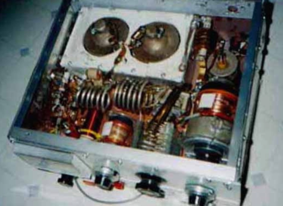 This high range amplifier is very small [SB200 size] Vacuum variable input and output caps as well input and output switching.
 -
 Sixty-four years of operating experience inform Glynn E. "Buck" Rogers Sr., K4ABT's, insights into the J-Pole antenna, which he describes as a direct descendant of the _Windom_ or _ZEPP_. His first article on the J-Pole appeared in HRC magazine in 1958, and he has since published numerous pieces in publications like CQ Magazine, consistently referring to the J-Pole as a Windom with a folded-back short section forming the parasitic element. He emphasizes that both the Windom and J-Pole are powerful multi-band antennas, performing exceptionally well at harmonics of their fundamental design frequency, and advocates for 50-ohm coaxial cable with a _BALUN_ at the feed-point to avoid RF energy losses. K4ABT details the J-Pole's features, noting its ease of erection, lack of radials, low angle radiation, greater bandwidth, and immunity to terrestrial noise. He highlights its suitability for local nets and distant repeaters, claiming more gain and durability than most ground planes, and its ability to meet stealth antenna requirements. The guide provides specific dimensions for 2-meter (145.000 to 146.000 MHz) and 6-meter (50.500 to 51.500 MHz) J-Pole antennas, including measurements for the long driven element, short tuning stub, and spacing. The construction section illustrates a modified feed technique using an SO-239 chassis-mount coax connector soldered into a copper tee, deviating from the usual hose clamp method. The author also discusses the use of _EMT_ (electrical metallic thin-wall conduit) as an alternative to copper in earlier days. He cautions against building a 75-meter J-Pole due to its impractical length, reinforcing the antenna's optimal application for VHF and UHF bands.
 -
 Demonstrates the construction of **magnetic loop antennas**, detailing both multi-turn and single-turn designs. It covers a 30-inch diameter multi-turn loop for 80 meters, based on a February 1996 QST article, and an octagon single-turn loop made from 15mm copper tube with a 4.8-meter circumference, operating from 7 MHz to 14 MHz. The document also presents a smaller 800mm diameter loop for 14 MHz to 28 MHz, emphasizing the importance of high-voltage tuning capacitors. Covers the design and construction of custom **butterfly capacitors** and piston capacitors, including a split stator capacitor with 140 pF capacitance and a 6000 Volt rating, and a butterfly capacitor with 5-65 pF and 7200 Volt rating. It explains why butterfly capacitors are preferred over split stator types for high power applications due to lower losses and direct series connection of rotors, reducing resistive losses from wiper contacts. Material recommendations include clear PVC for plates and brass or stainless steel for non-magnetic hardware. Addresses practical considerations such as feeding the loop with a shielded 1/5 Faraday loop made from RG213 or RG8 coax, achieving VSWR 1.1 across bands, and optimizing its placement 180° from the capacitor. It also discusses mechanical joint resistance, dissimilar metal oxidation prevention using Vaseline, and a simple method for determining radiation angle with a TL-light tube. The guide includes diagrams for rotor, stator, and end plate construction.
 -
 The antenna is nothing more than a simple 2.4 metre square loop drawing pinned to the internal brick wall of the spare bedroom. Yep, thats right, the inside wall of the spare bedroom - ideal for flat dwellers, hotel rooms or whinging neighbours, The loop has a simple switched inductance at the top of the square loop and uses a simple coaxial stub to tune the antenna. An additional variable capacitor placed across the feedpoint can be used to fine tune the resonance of the antenna, by Andy G0FTD
 -
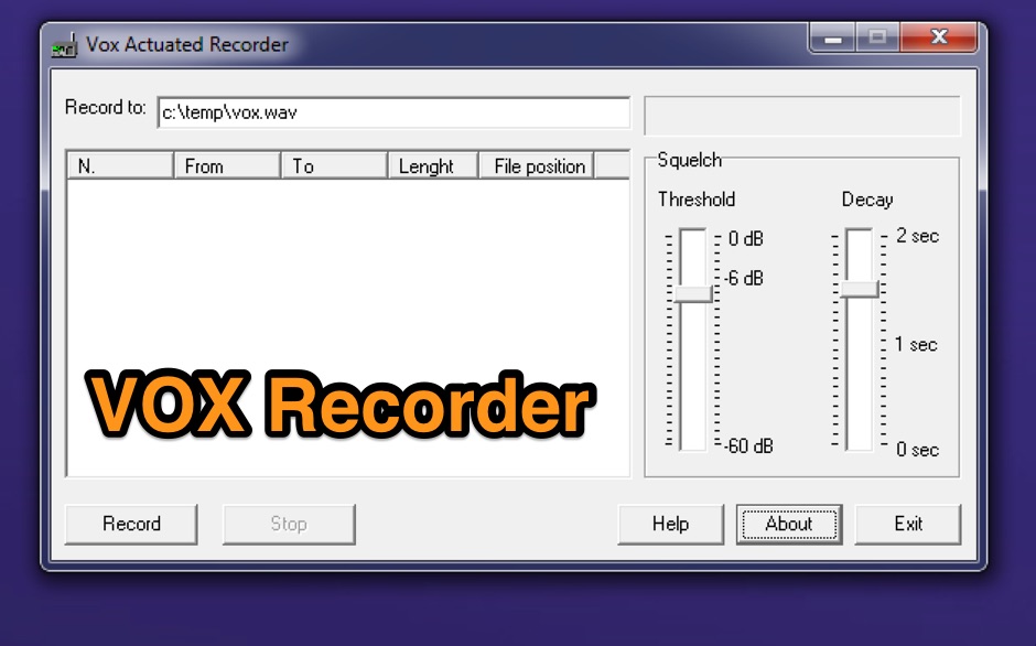 Vox Recorder is a specialized Windows utility designed for amateur radio operators, and radio listeners particularly those who use radio scanners. This software allows users to record audio from various sources, but it only activates when an audio signal is detected. This feature is particularly useful for avoiding the capture of silence or background noise, which can be common in radio scanning. By focusing on the audio signals, users can create cleaner recordings that are more relevant to their interests. The utility is user-friendly and tailored for hobbyists who want to document their radio listening experiences without the hassle of editing out silence later. Vox Recorder is an excellent tool for anyone involved in amateur radio, as it streamlines the recording process and enhances the overall experience of monitoring radio frequencies. Whether for personal use or for sharing with fellow enthusiasts, Vox Recorder helps ensure that every important transmission is captured effectively.
 -
 Great first time J-pole project. Covers most of the basics. This small and thin design also makes it good for several stealth applications.
 -
 Presents the WA7BNM Contest Calendar, a long-standing resource for amateur radio operators seeking contest schedules and rules. Bruce Horn, WA7BNM, compiles comprehensive listings that include an _8-Day Calendar_ for immediate planning, a _5-Week Calendar_ for near-term strategy, and a _12-Month Calendar_ for broader outlooks. The site also offers specialized views like the Perpetual Calendar for predictable events and a dedicated section for State QSO Parties. Operators can access historical data back to **2005** and customize their calendar views to filter for specific modes or QRP power levels. The calendar integrates with modern tools, providing RSS feeds, iCal downloads for desktop calendars, and direct links to Google Calendar for seamless integration. This resource is a staple for contesters, offering essential details like log due dates and links to official contest sponsor rules.
 -
 Super Morse is the original comprehensive Morse Code training program for the PC. Super Morse permits the user to learn the Morse characters in a very orderly way using several different methods, including one unique to Super Morse; build speed with special exercises
 -
 The only ACARS software to feature in-line message decoding and aircraft tracking. ACARS Reception and Decoding Software for legacy Windows versions. This software will allow you to decode the ACARS signals received by your air band receiver using the soundcard that is installed in you PC
 -
 SkySpy is a cheap Windows 95/98 software program combining a decoder and a database in order to decode ACARS transmissions, the digital data link between commercial aircraft and ground stations, demod ACARS FAX METEO POCSAG HAM. Software is no more supported and developed.
 -
 DigiPan provides a panoramic display of the frequency spectrum in the form of an active dial scale extending the full width of the computer screen. DigiPan is the result of a joint effort between myself and Nick Fedoseev, UT2UZ, the author of MIXW32, and is intended to make PSK31 operation easier and more enjoyable for everyone. You can download digipan 2.0 for windows form here.
 -
 A 9 dB gain 70cm collinear antenna construction is detailed, utilizing eight half-wavelength sections of _RG58/U_ coaxial cable. The design incorporates specific calculations for velocity factor (0.66 for RG58/U) to determine precise element lengths, such as 223mm for a half-wavelength at 444 MHz. A quarter-wave radiating element of #16 solid wire, 169mm long, is added to the top, and a 160mm aluminum tube acts as a quarter-wave counterpoise at the feed point. RF choke baluns, constructed from three _FT50-43_ toroids, are positioned a half-wavelength from the feed point to mitigate common mode current. Assembly involves soldering the coax sections in series, followed by SWR testing during construction and final mounting within a ¾-inch PVC pipe. The article suggests using four half-wave elements for a shorter antenna, noting a potential slight increase in SWR, which can be mitigated with quarter-wave ground radials. The design principles and formulas are scalable for other VHF/UHF bands like 6m, 2m, or 1¼m, providing a versatile homebrew solution for enhanced gain.
 -
 This resource presents the _FCC_ Online Table of Frequency Allocations, codified under 47 C.F.R. § 2.106. The document details frequency assignments across the electromagnetic spectrum, from 0 kHz to beyond 2170 MHz, specifying allocations for various radio services including amateur, maritime mobile, aeronautical radionavigation, and broadcasting. The table is structured with columns for International Table (ITU Radio Regulations Article 5, Section IV, 2019 Edition), United States Table (Federal and Non-Federal), and corresponding _FCC_ Rule Part(s). Specific frequency ranges, such as **135.7-137.8 kHz** and **472-479 kHz**, are identified with their primary and secondary allocations, including Amateur Radio (Part 97) and Maritime Mobile (Part 80). The methodology involves direct publication of regulatory data, reflecting amendments adopted by the _FCC_ that may not yet be codified in the Code of Federal Regulations. Each entry provides the allocated service (e.g., METEOROLOGICAL AIDS, RADIONAVIGATION), relevant footnotes (e.g., 5.53, US18), and the applicable _FCC_ Rule Part. For example, the 1800-2000 kHz range is allocated to AMATEUR radio under Part 97, alongside MOBILE services. Contact information for the Office of Engineering and Technology Policy and Rules Division is provided for inquiries regarding the data. DXZone Focus: Regulatory Database | FCC Publication | Frequency Allocation | Rule Part Reference
 -
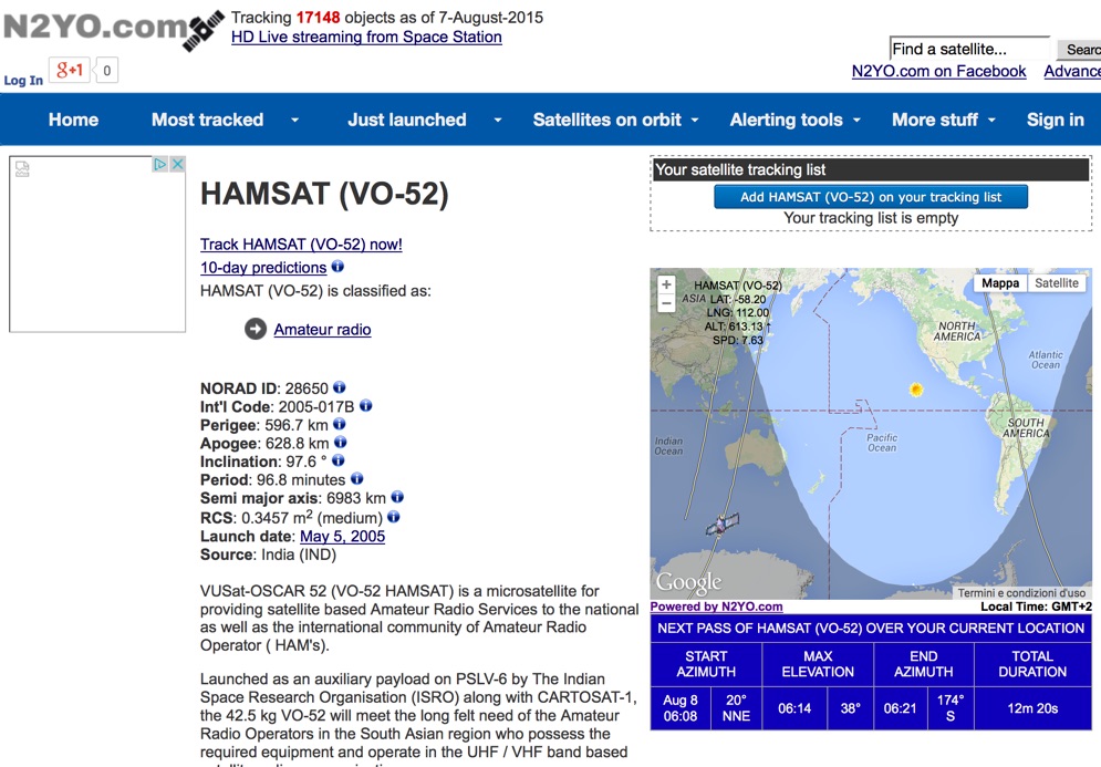 Select your favorite satellite and watch its trajectory on Google Maps in real time! Includes ISS tracking, Weather, Geostationary, GPS Military, and of course Amateur radio satellites. N2YO provides comprehensive real-time satellite tracking with particular emphasis on amateur radio satellites. The service offers precise pass predictions calculated for user-specific locations, displaying upcoming passes with azimuth, elevation, and duration data essential for ham operators planning satellite contacts. N2YO features dedicated tracking for amateur radio satellites including FM, linear transponder, and digital satellites, with frequency information and downlink/uplink details. The platform delivers live tracking visualizations on interactive maps, Doppler shift calculations, and automated email notifications for upcoming passes. This free resource integrates weather satellite tracking alongside NOAA imagery, making it invaluable for radio enthusiasts pursuing satellite communications.
 -
 HamCalc is a free collection of calculators for radio amateurs include Antenna ERP calculations, Attenuators, Audio Filter design, Coil Winding, Decibels, Great Circles map and calculator, HF Filters, HF Traps, Metric conversions OP Amps QRA Locator to Latitude/Longitude, Radio Horizon calculator, Resonance Satellite orbit calculator Timer calculations (555 timer)Zener Diode calculations Download zip By G4VWL
 -
 Optimizing the impedance transformation and common-mode current suppression in antenna systems often involves selecting an appropriate balun. This project presents a **hybrid balun** design, combining characteristics of both voltage and current baluns to achieve superior performance, particularly when used with an antenna tuner. The design addresses issues like **common-mode current** on the feedline, which can distort the antenna's radiation pattern and introduce RFI in the shack. The construction details include winding techniques for the toroid core, component selection, and practical considerations for integration into an existing antenna system. Performance comparisons are drawn against conventional balun types, highlighting the hybrid balun's effectiveness across the HF bands. The resource provides insights into the current distribution and impedance matching properties, crucial for efficient power transfer and reduced SWR.
 -
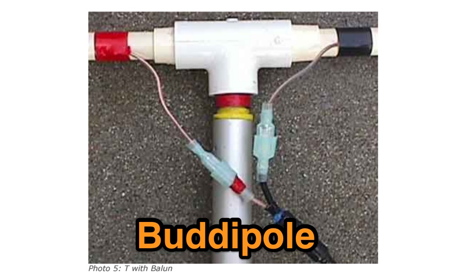 This is the antenna w3ff designed for his walking portable station. It is a dipole constructed out of the plastic plumbing pipe CPVC. There are telescoping whips at the ends of each side of the dipole, and these whips are adjusted to bring the antenna into resonance on each of five HF Bands 10, 12, 15, 17, and 20 Meters
 -
 WinDRM is the hottest digital mode on HF today! Nothing else exists where you can transfer data at almost 1KB/s without using proprietary hardware. HF Digital Radio Mondiale allow fast data, pictures, and voice over a 2.5Khz bandwidth. In this GDrive folder you can find a 2008 version of WinDRM for WIndows.
 -
 Presents a practical design for a **crossed-dipole turnstile antenna** specifically engineered for 2-meter Amateur Radio Direction Finding (ARDF) events. The author, WB6RDV, details a robust, omnidirectional, horizontally-polarized antenna, addressing the international ARDF rules requiring such characteristics at a height of two to three meters above ground. This contrasts with the vertical polarization often used in Southern California, highlighting the design's adherence to specific event requirements. The electrical design employs a classic crossed-dipole with a 75-ohm phasing section, resulting in a slight impedance mismatch and an SWR of approximately 1.3:1 with a 50-ohm feedline. Construction utilizes readily available and inexpensive PVC plumbing components and 1/8-inch bronze welding rod for elements. The guide provides step-by-step instructions for mechanical assembly, including drilling element holes at precise 90-degree spacing and preparing the RG-179 matching section. WB6RDV shares insights from his own build experience, discussing the use of plated brass versus aluminum spacers for element attachment and the effectiveness of crimping as an alternative to soldering. The document also covers final assembly, including the integration of ferrite beads as a choke balun and options for weatherproofing and alternative mounting configurations, emphasizing the adaptability of the design for other VHF bands through scaling.
 -
 Presents detailed plans and construction notes for a compact 3-element Yagi antenna specifically designed for the 50 MHz band, authored by Ken Willis, _G8VR_. The article, originally published in _Practical Wireless_ in 1989 and updated in 1999, outlines the design philosophy behind a small, gain-oriented antenna suitable for restricted QTHs. It covers element dimensions, boom length, and a unique coaxial _gamma match_ system, emphasizing a "plumber's delight" construction approach using readily available hardware. The resource details the author's operational experience, achieving _DXCC_ on 50 MHz with over 110 countries worked using this antenna. It also incorporates insights from computer simulation studies by _G3SEK_ and _W1XP_ using _MININEC_, which suggested minor adjustments to element lengths and spacing for improved front-to-back ratio, increasing it from 14dB to 31dB. The author compares theoretical performance with practical results, noting that while larger arrays might offer a few dB more gain, this compact design provides excellent performance for F2 propagation and general 6-meter DXing.
 -
 Examines the operational differences between **quad** and **Yagi** antenna designs, focusing on their respective performance characteristics for amateur radio applications. The document highlights key metrics such as forward gain, front-to-back ratio, and bandwidth, which are crucial for effective DXing and contesting. It discusses how element configuration, boom length, and material choices impact the efficiency and radiation patterns of each antenna type across various HF bands. Practical considerations for antenna builders are addressed, including structural integrity, wind loading, and overall weight, particularly when using fiberglass spreaders for quads. The resource also covers precipitation static reduction in quads due to their closed-loop design and their ability to operate efficiently at lower elevations compared to Yagis. It provides insights into dual-polarization feed systems for quads, offering independent vertical and horizontal feed points for enhanced operational flexibility.
 -
 A self-supporting vertical antenna design for stationary-mobile HF-VHF operation is presented, emphasizing ease of construction with common materials like a fiberglass fishing rod and PVC pipe. The design focuses on creating a set of no-tuner monoband radiators for bands such as **2m**, **6m**, 10m, and 12m, with an overall radiator support length of 3.3m. The construction process details the assembly of the antenna base using a magnetic mount, PL-259 connector, and PVC pipe sections, which then supports the telescopic fishing rod. Radiator extensions are cut to achieve quarter-wave resonance on specific bands, with detailed instructions for 6m (50-51 MHz), 10m (28.5 MHz), and 12m (24.9 MHz). For lower HF bands like 15m, 17m, and 20m, the design incorporates base-loading coils, with specific turn counts provided (e.g., 21 turns for 20m). The project also suggests using an _antenna analyzer_ for precise tuning of extensions and coils, moving beyond theoretical values to achieve optimal performance. The author, _IK1ZYW_, notes that for 80m and 160m, the antenna becomes less efficient as a vertical, suggesting alternative configurations like an inverted-V dipole or asymmetrical inverted-L.
 -
 The G3TPW CobWebb antenna design provides a compact, horizontally polarized, omni-directional solution for 20m, 17m, 15m, 12m, and 10m bands. This antenna utilizes five full-size half-wave dipoles, each bent into a square configuration to achieve omni-directional radiation without the nulls typically found in straight dipoles. The design incorporates a single 50-ohm coaxial feedline with an integrated air-core choke balun, minimizing feeder radiation and reducing EMC issues. Construction details include using PVC-covered multi-stranded copper twin cable for elements, supported by a fiberglass cross. The document specifies tapping points for impedance matching to 50 ohms on all five bands, ensuring high radiation efficiency without lossy traps or loading coils. Physical dimensions are compact, with 2.6-meter (8.5 feet) sides and a total weight of 6 kg (14 lbs), making it suitable for mounting on a 20-foot aluminum scaffold pole. Detailed instructions for assembling the junction box, including terminal strip wiring and the coaxial choke balun, are provided with photographs and diagrams. The design emphasizes a confined electric field to reduce coupling to nearby conductors, which helps mitigate TVI and makes the antenna less sensitive to mounting height or ground conductivity.
 -
 HF Wire Yagi antenna with notes and eznec file on original article of a Portable 3-Band Yagi antenna for 10-15-20 meter band made with wire elements. Include link the original to QST article.
 -
 This program descrambles band inverted encrypted transmissions, usually found on VHF/UHF. It uses a NCO (numerical controlled oscillator) to re-produce the originally inverted audio band. Use it only if legally permitted in your country. I assume no responsabilities deriving from its use. Standard disclaimer applies
 -
 Normal mode helix antennas offer a solution for HF mobile operators facing significant height restrictions, such as those parking in indoor garages with limited overhead clearance. This design, adapted from concepts typically applied to VHF/UHF rubber duck antennas, allows for extremely shortened HF radiators that remain effective for county hunting and general mobile operation. The resource details the construction of a 20-meter helix antenna, approximately 10 inches long, wound with #14 AWG THHN wire on a 1 1/2-inch CPVC form, mounted on a standard 3/8 x 24 antenna stud. Mark Herson, _N2MH_, shares his experience developing these antennas, including initial research from the _RSGB VHF UHF Manual_ and practical winding experiments to establish the relationship between turns and resonant frequency. He provides coil data for various frequencies, emphasizing that these measurements were taken with an _MFJ-259a_ antenna analyzer and are dependent on the vehicle's grounding system. Despite their shortened nature, N2MH confirms the antennas' operational effectiveness, citing contacts with KL1V in Alaska on 20 meters and E-skip contacts on 10 meters. The design prioritizes continuous deployment without removal, making it suitable for operators who frequently navigate height-restricted environments.
 -
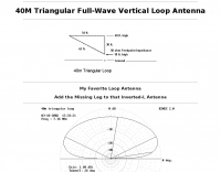 A 40 meters band full wave antenna project plan with model, adding the Missing Leg to the Inverted-L Antenna
 -
 Building a directional antenna for limited space, M0MRR shares his experience constructing a 10-meter Moxon rectangle. Initially using fiberglass fishing poles and a plastic breadboard, he achieved a 1:1.2 SWR across the band with 50 watts, making contacts as far as PY2TO from the UK. The design incorporates 10-amp power cable for elements and RG58 coax with crocodile clips for feeding, demonstrating a cost-effective approach. His field observations confirm the directional properties, noting European signals fading when facing Stateside, and receiving better reports from stations in the antenna's favored direction. While not formally measured, the front-to-back ratio appears effective. The initial build was somewhat flimsy, intended for temporary deployment, but proved effective for DX. Later, M0MRR constructed a more robust 10-meter Moxon using tubular aluminum pipe, indicating an evolution in his design approach for durability. The project highlights practical antenna building for small backyards, emphasizing the benefits of a directional antenna even with modest power.
 -
 This drawing shows a simple 10 meter wire J-pole antenna designed for 28.4 MHz. It is a vertical, end-fed Zepp-style antenna made from common materials and intended for easy home construction. The main radiating element is a straight length of stranded copper wire, either 14 or 18 gauge, cut to about 16.5 feet. At the top, the wire is supported by an insulator, allowing the antenna to be hoisted vertically. The matching section is made from 450-ohm ladder line, approximately 7 feet 9.5 inches long, and shorted at the bottom. This matching stub transforms the impedance so the antenna can be fed with coaxial cable. The feed point is tapped about 6 inches above the bottom of the stub, with the shield and center conductor connected at the proper points. A choke balun is formed with five turns of RG-58 coax in a 4-inch diameter loop to help reduce unwanted RF on the feed line. The drawing notes that this antenna has about 0 dBd gain, similar to a dipole, but offers an omnidirectional pattern and low-angle radiation when installed high. Its main advantage is practical performance, simple construction, and effective coverage for 10 meter operation.
 -
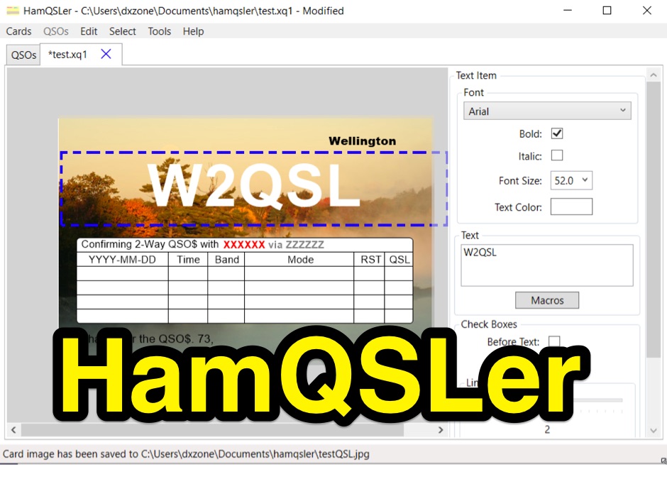 A program to design and print QSL cards on your computer, as well as design QSL cards for printing by commercial printers. This program overcomes many of the limitations that are present in other QSL design and print programs and methods. Works on Windows 7 to 10.
 -
 The 20-meter homebrew **Moxon antenna** project by 9Y4DD, Dave, details the construction of a 14 MHz directional antenna using readily available and repurposed materials. Initial SWR readings at 6 feet were 1.2 at 14.000 MHz, 1.4 at 14.350 MHz, and 1.1 at 14.175 MHz, with a subsequent increase of 0.1 on all frequencies when raised to 15 feet. The design adheres to specifications provided by L.B. Cebik (W4RNL). Key components include a discarded domestic water pump pressure tank as the center mounting bracket, 1/2-inch PVC conduit for spreaders, and 1/2-inch CPVC hot water pipe inserts to enhance rigidity. The total weight of the antenna is 12.625 pounds, with a material cost of U.S.$36.63. The spreaders are 165 inches from the center, utilizing 2.5mm sq. stranded copper wire for the elements. Dave's design incorporates hexagonal 'spider webs' of waxed twine to stabilize the flexible PVC spreaders, addressing initial issues with wind-induced movement. Separators cut from 3/16-inch Plexiglas maintain an 8.6-inch element spacing. The antenna demonstrated effective DX contacts with Europe from Trinidad, showing improved noise reduction compared to an inverted V.
 -
 M1PAF's 20 Meter Vertical Moxon antenna design, based on Pete Mills' EZNEC model, utilizes a push-up GRP mast and Tufnol plate for mounting cross arms, minimizing metallic elements within the beam. Hydraulic pipe clamps, also plastic, secure the tube clamps, with only two bolts and a plate being metallic. Dog bone insulators with Kevlar line and snap links facilitate quick wire element attachment, ensuring tension in all dimensions. The antenna's support structure includes Tufnol guying rings for Kevlar guys, providing stability against high winds. The cross arms are constructed from three 1-meter sections, allowing for convenient packing. This portable setup was successfully deployed adjacent to the ocean, enabling over 4500 QSOs in six days with 100W, achieving easy contacts into Japan and Asia. The design emphasizes ease of erection by a single operator and robust performance in challenging environments. Components for the cross arms were sourced from Spiderbeam. Further information is available via M1PAF's QRZ.com details.
 -
 The _Astron RS35m Power Supply Schematic_ provides a detailed circuit diagram for this popular linear power supply, focusing on the rectifier and pass transistor stages. It presents the AC input and DC output sections, illustrating the component layout and interconnections critical for understanding its operation. The schematic is enhanced with specific annotations derived from the December 2005 QST "Hands-On Radio, Experiment #35 Power Supply Analysis." These notes offer insights into the circuit's functionality and potential analysis points, making the diagram more instructive than a bare schematic. The resource serves as a practical reference for hams interested in the internal workings or maintenance of the _Astron RS35m_ unit. This document specifically highlights the key components responsible for voltage regulation and current delivery.
 -
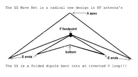 ZZ Wave Net is a 40 & 80 meter full wave loop designed to fit on a city lot. ZZ Antenna is a folded dipole bent into an inverted V loop
 -
 EasyPal is a sophisticated digital Slow-Scan Television (SSTV) application that utilizes soundcard technology to encode and decode SSTV signals. Developed by the late Erik Sundstrup (VK4AES SK), this software has evolved into a versatile communication tool for amateur radio operators, extending beyond basic image transmission capabilities. EasyPal implements Digital Radio Mondiale (DRM) encoding technology, enabling efficient data transmission over narrow 2.5 KHz channels on both HF and VHF frequencies with remarkable speed. The application supports multiple file formats, including jpg, pdf, txt, doc, and xls, as well as specialized forms such as ICS-213 and ICS-213 (ARES). Additionally, EasyPal offers email functionality through designated repeater stations with internet access. Its responsive development history and robust feature set have established it as a premier digital SSTV solution in the amateur radio community, though users of Windows 11 should note specific configuration requirements to ensure optimal performance.
 -
 The PringlesCantenna is an ultracheap Yagi-type directional antenna that can be built for under $10. The original Pringles Yagi was designed by Andrew Clap.
 -
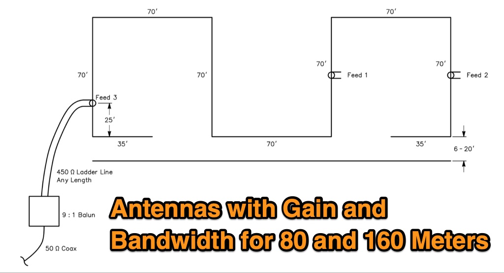 The Bruce array is a simple, often-forgotten wire antenna array that is advantageous for 80 and 160 meters, where typical gain antennas are very large. This bi-directional broadside vertical array is only 1\4 lambda high and does not require a ground system. It offers substantially greater SWR bandwidth than the half-square or bobtail curtain. A 4-element Bruce array used by N6LF showed a gain of about 4.6 dB compared to a 1\4 lambda vertical with 8 elevated radials, with a 2:1 SWR bandwidth greater than 400 kHz. The antenna is simple and its dimensions are flexible.
 -
 This project details three variants of a vertical half-wave antenna design for the 4-meter (70MHz) amateur radio band. The antennas use end-feeding with a parallel-tuned circuit for impedance matching to 50-ohm coaxial cable. The first variant uses suspended flexible wire for portable use, the second employs a fiberglass rod with internal wire for permanent outdoor installation, and the third utilizes aluminum tent poles for quick mobile deployment. Despite the narrow bandwidth of the matching circuit, this suits the narrow 4m FM allocation well. The design offers an effective omnidirectional radiation pattern and can be constructed with readily available materials.
 -
 Presents a crystal-controlled CW transmitter design for the 40-meter band, delivering 5 to 7.5 watts output power. The circuit innovatively employs an _IRF510_ power MOSFET in the final amplifier stage, diverging from conventional bipolar transistors. This design offers high gain, nearly 90% efficiency, and robust resistance to high SWR, allowing 30-second key-down operation into an open circuit without damage. A critical aspect is the precise adjustment of the MOSFET gate bias via a 10K trimmer pot, _R10_, to maintain quiescent current between 5 and 10 mA, preventing thermal runaway inherent to bipolar devices. The prototype was constructed on a _Radio Shack universal board_ and achieved immediate operational success. The design requires a 15-volt Zener diode to protect the MOSFET gate from overvoltage. Component sourcing information is provided, including specific crystal frequencies (7.040 MHz or 7.122 MHz) available from _Dan’s Small Parts & Kits_ or Doug Hendricks. The fixed frequency can be slightly adjusted with a trimmer capacitor. A complete bill of materials, including resistor values, capacitor types, toroid specifications, and transistor part numbers, is detailed, alongside a clear schematic diagram.
 -
 Presents a detailed construction guide for a 2-element _Moxon rectangle_ antenna optimized for the 10-meter band, designed by L. B. Cebik, W4RNL (SK). This resource demonstrates how to build a compact beam antenna using readily available hardware store aluminum tubing, fitting within a 12-13 foot width. It highlights the antenna's performance characteristics, including a gain comparable to a 2-element Yagi (11+ dBi) and a front-to-back ratio exceeding 20 dB between 28.3 and 28.5 MHz, with an SWR below 2:1 across the entire band. The design emphasizes direct 50-ohm coax connection without a separate matching system, though a 1:1 choke _balun_ is recommended. The guide provides practical advice on element construction, corner fabrication using L-stock or radius-bent tubing, and the critical side-to-side length adjustment for SWR optimization. It details the feedpoint assembly using a chassis-mounting coax connector and discusses element-to-boom plate options, including spar varnished plywood or LE plastic. The author's experience with a test model on a 20-foot mast confirms stable feedpoint characteristics and excellent performance even at lower heights. The document also includes insights into the antenna's free-space azimuth patterns, noting a broad forward lobe and significant front-to-back rejection. It contrasts the Moxon with traditional Yagis, positioning it as an effective, home-buildable alternative for compact sites or _Field Day_ operations, particularly beneficial during periods of increased 10-meter activity.
 -
 SM0DTK's 40-meter Moxon antenna project details the construction and deployment of a wire Moxon rectangle, specifically dimensioned for the 7 MHz band. The resource outlines the use of a _Moxon Rectangle Generator_ for calculating wire lengths and the fabrication of plexiglass supports for corners and the feeding point. It describes the practical challenges of elevating the antenna to approximately **14 meters** using an aluminum tube and fiberglass rod, emphasizing the adjustment process for achieving the correct rectangular shape. The article presents comparative results against a 60-meter long-wire and a full-size 40-meter ground plane antenna. The Moxon demonstrated significant directional gain towards the west, facilitating DX contacts in the Caribbean with **100 watts**, while simultaneously reducing QRM from strong eastern European stations. The SWR was reported as perfect without the need for an antenna tuner, validating the design's effectiveness for targeted signal enhancement and interference mitigation.
 -

-
 A 70 MHz Moxon rectangle antenna, built with 0.83mm enamelled copper wire and a lightweight fiberglass kite spar frame, offers a compact two-element beam solution for the 4-meter band. This design, originally for HF, scales effectively to VHF, reducing the antenna's width to approximately 75% of a half-wavelength while allowing direct coaxial cable feeding. The author, G6GVI, details the construction process, including the use of an automated design tool for precise dimensions. Initial field testing revealed a VSWR of approximately 1.3, with distinct nulls observed at 90 degrees when the antenna was mounted horizontally. The lightweight build, supported by a wooden block and U-bolt for mast attachment, makes it suitable for thinner mast sections. Further experimentation included testing with vertical polarization and considering its potential for indoor loft installation due to its relatively short major axis, offering a discreet option for urban hams.
 -
 This resource details the construction and feeding of a vertical Moxon antenna specifically designed for the 20-meter band (14 MHz). It addresses the common issue of impedance variations at the feed point of vertical dipoles and Moxons, which typically requires the coax to exit at a specific angle (45-90 degrees) to maintain a good 50-ohm match. The presented solution involves opening the lower corner of the fed element and utilizing a transformer for impedance matching, simplifying installation and improving SWR. The alternative feeding method provides a stable match, eliminating the need for precise coax routing to achieve a low SWR. This design offers a practical improvement over conventional vertical Moxon feeding, making deployment significantly easier. The author, SM0DTK, confirms the efficacy of this setup, noting its fine performance and reduced installation complexity compared to traditional methods.
 -
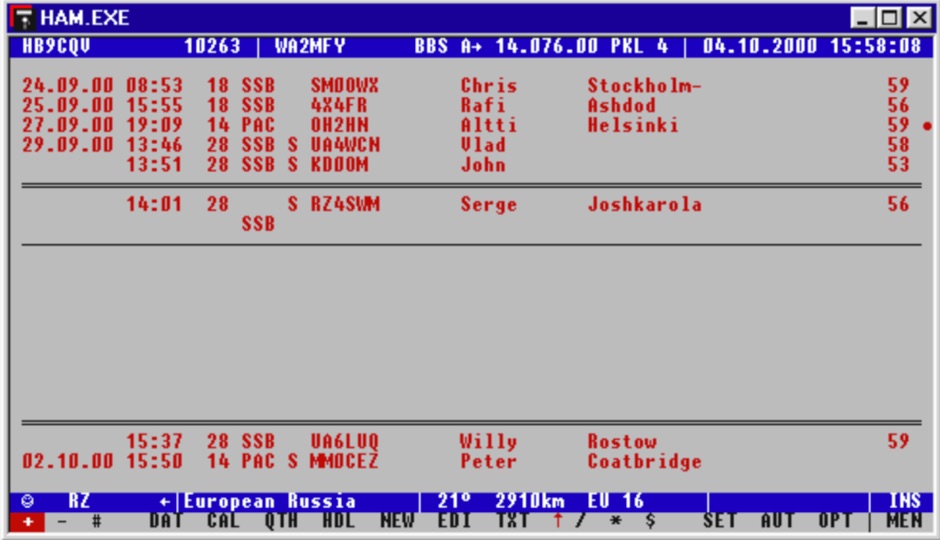 Facilitates efficient logging of amateur radio contacts, offering a robust solution for hams managing their station activities. The software integrates _CAT control_ capabilities, allowing direct interfacing with popular transceivers from manufacturers like Yaesu, Icom, and Kenwood. This feature streamlines the logging process by automatically capturing frequency, mode, and other QSO details directly from the radio, reducing manual entry errors and improving operational efficiency during contests or DXing. _HAM-LCT_ includes a comprehensive database, enabling users to store and retrieve contact information, QSL data, and other relevant details for each QSO. The program supports various operating modes and provides tools for searching and filtering log entries, which is beneficial for award tracking and station analysis. Its design focuses on providing a user-friendly interface for everyday logging tasks. While the original author, _HB9CQV_, has discontinued development of HAM-LCT in favor of a newer logging application, this version remains available as a functional freeware option for Windows users seeking a dedicated logbook with integrated rig control.
 -
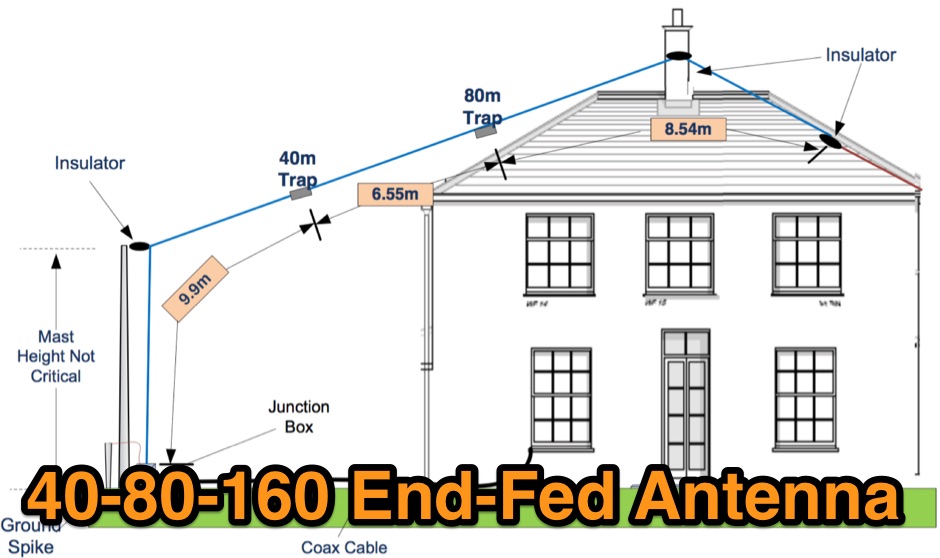 This PDF File desscribes how to homemade a multi-band end-fed trapped wire antenna resonating on the low bands of 160 80 and 40 meters. Contains trap design instructions and some construction tips.
 -
 This article addresses the subject of obtaining the best signal transfer from an antenna to the typical 50-ohm receiver input over a wide frequency range, with emphasis on medium-wave (500 - 2000 kHz), encompassing the standard AM broadcast band and the 160-m amateur band.