Search results
Query: ground antenna
Links: 248 | Categories: 5
-
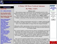
 Demonstrates the construction of a **multi-band HF mobile antenna** utilizing a modified CB whip antenna base. The resource details the process of stripping a commercial CB whip, winding a new helical coil with 0.7mm insulated copper wire, and identifying tapping points for various HF bands. It emphasizes the importance of a rugged, slim design for mobile operation, discussing mechanical length, power handling (up to 200 watts), and coil diameter considerations. The article includes a graphic illustrating the antenna's operational principle, where sections of the helical coil are shorted from bottom to top to maintain efficiency and high Q. The resource presents a practical approach to achieving **band switching** without an external tuner, by manually adjusting tapping points on the coil. It provides a table with reference lengths in centimeters from the feedpoint for 7 MHz (40m) through 28.7 MHz (10m), including WARC bands. The author details mounting techniques, suggesting a Diamond bracket for secure attachment to a vehicle trunk, and stresses the critical role of proper grounding for optimal performance. The design allows for operation on 75m and 80m bands by adding a 110mm steel whip.
 -
 Author evaluated a custom-built passive AM loop antenna, achieving notable DX reception including KLBJ Austin (230 miles) and WWL New Orleans (700 miles). The antenna operates solely on resonant inductive coupling, enhancing weak signal reception without external amplification. This project illustrates how fundamental RF design—calculating inductance, capacitance, and Q factor—can significantly boost performance of consumer-grade radios. Detailed construction techniques, theoretical background, and optimization strategies for effective loop antenna design are presented for amateur and experimental use.
 -
 2-Element parasitic Yagis for the Shortwave-Bands 10-12-15-17-20-30m. The antennas are feeded with the DK7ZB-match. A quarter-wave choke of coax is grounded at the socket.
 -
 The **Extended Double Zepp** (EDZ) antenna, a simple wire design, is presented as a means to achieve 3-4 dB of gain on 10 meters, with an overall length of just 43 feet. This resource, authored by WB3HUZ, details several gain antennas suitable for the 29 MHz AM segment, all modeled using EZNEC software at 30 feet above ground. Other designs include a compact rectangular loop, offering more gain than the EDZ and a lower take-off angle, and the **Lazy H**, a bidirectional antenna providing 6 dB gain, which is also workable on 20, 17, 15, and 12 meters. The Bisquare, a diamond-shaped open-top loop, is also featured, providing approximately 4 dB gain and requiring only a single support. These designs are primarily fed with ladder line or open-wire line to simplify matching, though a coax feed option for the EDZ is shown for 10-meter-only operation. The Lazy H, for instance, requires about 16 feet of open-wire line for its half-wavelength elements spaced a half-wavelength apart. An enhanced EDZ Lazy H variant is also discussed, achieving an additional 1-2 dB gain by extending element length to 1.28 wavelengths and increasing spacing to 0.64-0.75 wavelengths. The Bisquare, while primarily a 10-meter antenna, can be adapted for 20 meters by closing the top connection.
 -
 This PDF article from April 2001 QST details the construction of the "NJQRP Squirt," a reduced-size 80-meter inverted-V dipole antenna. The resource provides a general construction sketch, a photograph of the assembled antenna, and specific dimensions for PC-board insulators. The antenna consists of two wire legs, each approximately **34 feet long**, separated by 90 degrees, fed at the center. It is designed for operation on 80 meters (3.5-4.0 MHz) as a quarter-wavelength antenna, requiring a low-loss feedline and an external antenna tuner due to its non-resonant feedpoint impedance. Construction utilizes readily available materials, including 1/16-inch glass-epoxy PC board for end and center insulators, and #20 or #22 insulated hookup wire for the elements. The feedline specified is 300-ohm TV flat ribbon line, with a note on potential trimming for tuner compatibility. N2CX reports the antenna's center should be elevated to at least **20 feet**, with ends no lower than seven feet above ground, resulting in a ground footprint of approximately 50 feet wide. The design prioritizes NVIS propagation for local 80-meter contacts. DXZone Focus: PDF Article | 80m Inverted-V Dipole | Construction Notes | 34 ft element length
 -
 Here is a sure fire way to make end-fed halfwave antennas fed with a 50 ohm coupler work - without long radials, grounds, chokes, voodoo.
 -
 The page describes a Double-L antenna for 80 and 160 meters bands, designed by Don Toman, K2KQ, with a simple, effective, and ground system-free design. The antenna is a center-fed half-wave vertical with horizontal top and bottom sections, providing good performance without the need for an elaborate ground system.
 -
 Build your mobile antenna which outperforms Hustler by 10db and ATAS-100 by 18db. From 80 to 10m. The HB9ABX mobile HF antenna, designed for 10 to 80 meters, was developed by Felix Meyer and outperforms commercial antennas like HUSTLER and YAESU ATAS-100/120 in field tests. Made from fiberglass rods and enamelled copper wire, it includes a loading coil with adjustable taps for tuning across bands. Installation requires solid grounding, and adjustments are made via whip length and coil settings. An antenna tuner ensures optimal SWR. Users must handle fiberglass with care due to health risks. This design proved highly effective in South America and Europe.
 -
 Need a general purpose antenna on the magic band? The J-Pole is an easy-to-build and inexpensive device that provides an omni-directional vertically polarised antenna without the need for a ground plane. In technical terms, it is an end fed vertical 1/2 wave which is fed via a 1/4 wave matching stub.
 -
 A 9 dB gain 70cm collinear antenna construction is detailed, utilizing eight half-wavelength sections of _RG58/U_ coaxial cable. The design incorporates specific calculations for velocity factor (0.66 for RG58/U) to determine precise element lengths, such as 223mm for a half-wavelength at 444 MHz. A quarter-wave radiating element of #16 solid wire, 169mm long, is added to the top, and a 160mm aluminum tube acts as a quarter-wave counterpoise at the feed point. RF choke baluns, constructed from three _FT50-43_ toroids, are positioned a half-wavelength from the feed point to mitigate common mode current. Assembly involves soldering the coax sections in series, followed by SWR testing during construction and final mounting within a ¾-inch PVC pipe. The article suggests using four half-wave elements for a shorter antenna, noting a potential slight increase in SWR, which can be mitigated with quarter-wave ground radials. The design principles and formulas are scalable for other VHF/UHF bands like 6m, 2m, or 1¼m, providing a versatile homebrew solution for enhanced gain.
 -
 The J-Pole antenna is an omnidirectional antenna that can be used for base, mobile and field day stations. It does not need a ground plane, radials or a complicated matching system. The J-Pole can be cheaply, simply and quickly constructed using a variety of techniques, some of which are discussed in this article.
 -
 The RXO Unitenna, a vertical wideband antenna, offers operation across the 7-21 MHz spectrum, covering the 40, 30, 20, 17, and 15-meter amateur bands. This design focuses on achieving a low SWR across a broad frequency range, making it suitable for general HF operation without requiring an external antenna tuner for minor SWR variations. The antenna utilizes a unique loading coil and matching network to maintain efficient radiation characteristics across its operational bandwidth. Construction details within the PDF document include specific dimensions for the radiating element and the counterpoise system, which is critical for vertical antenna performance. The design incorporates readily available materials, simplifying the build process for radio amateurs. Performance graphs illustrate the SWR characteristics across the 7 MHz to 21 MHz range, demonstrating the antenna's wideband capabilities. The document also provides guidance on feedline connection and grounding considerations for optimal field deployment. This vertical antenna configuration is particularly useful for hams with limited space, offering a compact footprint compared to horizontal wire antennas.
 -
 This article describes how an effective ground system can be produced for a short vertical antenna.
 -
 Suggestions on finding RF ground when you live in an apartment and you want to setup an antenna
 -
 End-Fed antennas are NOT balanced systems; but neither are verticals, ground planes, discones, windoms, zepps, Marconis, half-slopers, et al. Additionally, the low-impedance antenna port of your transmitter/receiver is not balanced.
 -
 This Vertical antenna design by David Reid for lower bands focuses on achieving effective DX communication by optimizing the antenna low-angle radiation for long-distance contacts. The design incorporates techniques like linear loading and capacity hats to reduce the antenna's height while maintaining performance, especially on 40m and 80m bands. Building a solid ground plane and using quality materials ensure efficiency and durability. Although vertical antennas can be complex to build, this project simplifies the process, making it accessible for ham operators seeking strong, reliable signals.
 -
 How High should my Dipole be? Dipole Antennas and the effect of height above ground. The effectiveness of a dipole antenna is influenced by its height above ground, determined by the intended use such as DX work, local communication, directionality, omni-directionality, and feed point impedance. Through EZNEC modeling, the study evaluates a 40-meter dipole's performance at various heights, from 7 to 560 feet. Findings reveal that lower heights enhance omni-directional local communication, while higher placements favor DX work with low-angle radiation. The study emphasizes the importance of defining operational goals to optimize dipole height and performance.
 -
 Details the construction and optimization of antenna systems for amateur radio satellite operations, focusing on practical, homebrew solutions for VHF/UHF bands. It covers building _groundplane antennas_ from salvaged materials, recycling old beam antennas into new configurations like a 2-meter crossed yagi, and constructing a 10-meter horizontal delta loop. The resource also explains antenna matching techniques, including folded dipole driven elements and quarter-wave transformers, along with the importance of accurate SWR measurements and minimizing coax loss. Demonstrates how to achieve a **1:1 SWR** by carefully trimming elements and adjusting radial angles on groundplane antennas. It provides insights into selecting appropriate coax and connectors, highlighting the benefits of Belden 9913 for low loss and the proper installation of _N-connectors_. The article also addresses RFI mitigation from computer birdies and presents a design for a silent triac antenna control circuit, offering practical solutions for common satellite station challenges.
 -
 The G3JVL 6 Meter ground plane vertical is a compact antenna that is ideal for portable operations. If needed, it can be disassembled into a very small bundle no longer than the longest element.
 -
 Homebrew a 5/8 wave ground plane antenna for 10 meter band. Interesting article with lots of pictures and homebrew details.
 -
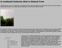 The Shunt-fed Tower, an effective Low Band Antenna, uses your beam as a capacitive top-hat and only needs a simple feed network and a good ground system to work DX on 80M and 160M.
 -
 Presents a practical design for a **crossed-dipole turnstile antenna** specifically engineered for 2-meter Amateur Radio Direction Finding (ARDF) events. The author, WB6RDV, details a robust, omnidirectional, horizontally-polarized antenna, addressing the international ARDF rules requiring such characteristics at a height of two to three meters above ground. This contrasts with the vertical polarization often used in Southern California, highlighting the design's adherence to specific event requirements. The electrical design employs a classic crossed-dipole with a 75-ohm phasing section, resulting in a slight impedance mismatch and an SWR of approximately 1.3:1 with a 50-ohm feedline. Construction utilizes readily available and inexpensive PVC plumbing components and 1/8-inch bronze welding rod for elements. The guide provides step-by-step instructions for mechanical assembly, including drilling element holes at precise 90-degree spacing and preparing the RG-179 matching section. WB6RDV shares insights from his own build experience, discussing the use of plated brass versus aluminum spacers for element attachment and the effectiveness of crimping as an alternative to soldering. The document also covers final assembly, including the integration of ferrite beads as a choke balun and options for weatherproofing and alternative mounting configurations, emphasizing the adaptability of the design for other VHF bands through scaling.
 -
 How to build a beverage antenna. How to deploy a BOG antenna for your next SWL DX-ing activity. Give it a try and follow the orientation tips for this bi-directional antenna.
 -
 Types of beverage wires, choose best supports and insulators, multiple antennas at one feedpoint, all well documented with photos and exaustive explanation. This article offers insights on building Beverage antennas for optimal reception. Key takeaways include using strong wire (copperweld or electric fence), proper termination, and a good grounding system (multiple copper rods). The author recommends maximizing antenna length and orienting it towards desired stations. For best results, utilize an antenna tuner and experiment with termination resistors.
 -
 Presents the KE4UYP linear-loaded vertical antenna design, which introduces very little loss on 80 or 160 meters, achieving an overall radiation efficiency of 80% to 85%. This design addresses common pitfalls of traditional base-fed verticals by placing the majority of the current at the top of the antenna, eliminating the heavy reliance on extensive ground radial systems. The author's initial 10-meter model, only three feet tall, yielded 5/9 signal reports to Anchorage, AK, and Europe, confirming its effectiveness. The antenna incorporates both vertically and horizontally polarized radiators, with a 1/4 wavelength horizontal counterpoise located at the feed-point, near the top, to create an almost totally omnidirectional pattern with high wave angle horizontally polarized radiation. This dual polarization ensures even illumination across all take-off angles, making it effective for both local contacts and **DXing**. The vertical element is linear loaded, adding capacitance reactance and making it longer than the horizontal element to achieve resonance and raise the feed-point impedance to 50 ohms. Fine-tuning the antenna requires careful adjustment, as tower reactance can vary. The article suggests starting with 80 feet for 80m and 170 feet for 160m for the vertical wire, then trimming for resonance. Bandwidth specifications include 300 kHz under 2:1 **SWR** on 80m and 100 kHz on 160m when suspended between trees, or 150 kHz on 80m when side-mounted on a tower.
 -
 The Bruce array is a simple, often-forgotten wire antenna array that is advantageous for 80 and 160 meters, where typical gain antennas are very large. This bi-directional broadside vertical array is only 1\4 lambda high and does not require a ground system. It offers substantially greater SWR bandwidth than the half-square or bobtail curtain. A 4-element Bruce array used by N6LF showed a gain of about 4.6 dB compared to a 1\4 lambda vertical with 8 elevated radials, with a 2:1 SWR bandwidth greater than 400 kHz. The antenna is simple and its dimensions are flexible.
 -
 We worry a lot about Standing Wave Ratio (SWR) in amateur radio since SWR is one indication of how well our antenna system is working. Most HF transceivers and antenna tuners have built in SWR meters. SWR is a measure of a transceiver' s output power verses the portion of that power reflected by the antenna system
 -
 Demonstrates the construction and performance of an updated ZS6BKW multiband dipole, a variant of the _G5RV_ antenna, specifically designed for HF operation. The article details a real-world installation using 13.5m copper wire elements and 12.2m of 450 Ohm ladder line, configured as a sloping inverted-V with the apex at 10m and ends at 4m above ground. It covers the critical aspect of impedance matching, incorporating an 8-turn choke balun at the feedline transition to RG-58U coax to mitigate RF common mode current. Measurements confirm favorable SWR readings below **1.3:1** on 7.1 MHz, 14.11 MHz, 18.06 MHz, and 24.8 MHz, indicating effective resonance across 40m, 20m, 17m, and 12m bands. The installation also shows usable SWR dips on 3.55 MHz (5:1), 29.02 MHz (2:1), and 50.84 MHz (3:1), extending its utility to 80m, 10m, and 6m with an antenna tuning unit. Initial on-air results report clear reception of stations over **5000km** away, validating its DX potential.
 -
 The Inverted L antenna is a versatile and efficient design suitable for small gardens, allowing amateur radio operators to operate on multiple bands. This project outlines the construction of a 5-band inverted L antenna, which can cover HF bands effectively. The design is particularly advantageous for those with limited space, as it requires minimal ground space while providing good performance. The antenna can be easily constructed using common materials, making it accessible for both beginners and experienced hams. In this guide, GM0ONX shares detailed instructions on how to build the inverted L antenna, including dimensions and tuning tips. The project emphasizes the importance of proper installation and grounding to ensure optimal performance. Additionally, it discusses the antenna's compatibility with various transceivers and the potential for portable operation. This resource is ideal for hams looking to enhance their station with a multiband antenna that performs well in limited space.
 -
 How High should my Dipole be? Dipole Antennas - the Effect of Height Above Ground
 -
 Perfect ground vs. poor ground. What is the difference? How does the ground influence the DX-gain?
 -
 Interesting article on mobile antennas by Cebik. . The article offers advice for setting up and operating mobile antennas for ham radio use. It emphasizes the lossy nature of mobile-in-motion antennas but encourages users to rise to the challenge. Steps include safeguarding car electronics, choosing proper cabling, and carefully selecting and mounting antennas. It highlights potential issues like roof mounting, trunk lip grounding, and side-mounting for trucks. For stationary operation, options like dipoles or beams are explored, with safety tips for masts and guying systems. Lastly, it stresses safety, suggesting stopping the vehicle to operate whenever possible
 -
 A 20 meter quarter wave vertical antenna by jerry sevick W2FMI QST Article
 -
 A **90-foot tall** top-loaded vertical antenna for the 160-meter band is detailed, constructed from aluminum irrigation tubing. The design incorporates four sets of four guy wires for structural stability, essential for an antenna of this physical size. This _monoband_ vertical is optimized for low-band operation, providing a robust solution for DXing and contesting on 1.8 MHz. The document includes specific construction methods for assembling the aluminum irrigation tubing sections and securing the guy wires. While a full NEC model is not explicitly provided, the physical dimensions and construction materials are sufficient for replication by experienced builders. The antenna's height and top-loading configuration are critical for achieving efficient radiation on 160 meters, particularly in minimizing ground losses.
 -
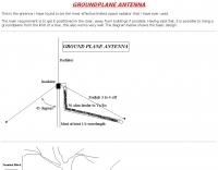 Short guide to build your own groundplane antenna, includes radial measurements fro warc bands
 -
 A rotary trapped-dipole for 17 and 20 meters, as described by IZ7ATH, presents a practical solution for multi-band HF operation. The author, Talino, recounts his experience building this antenna for IK7ZCQ, detailing the evolution from an initial concept involving a grounded-driven element and gamma-match to a direct-fed, non-grounded design. His pragmatic approach, adapting available materials, is evident throughout the construction narrative, particularly with the use of eight tapered aluminum pipes for the driven element. Construction specifics include precise measurements for the aluminum tubing, with diameters ranging from 30 mm down to 16 mm, and a critical note on reducing tip thickness for weight optimization. The _traps_, initially a concern, are fabricated using 8 turns of RG58 coax on a 27 mm support, tuned to resonate at 18.1 MHz using a dip-meter. Talino emphasizes sealing the traps with RF glue and PVC tape to prevent water ingress, a crucial step for longevity. Field test results, conducted on a 10-meter pole in a clear garden environment, showed an SWR of 1.2:1 on 17 meters and 1.5:1 at 14.200 MHz. While SWR varied slightly when installed at Mario's QTH due to nearby objects, the antenna's performance remained commendable. The final half-dipole length is 46 cm for the 18 MHz tips, and the total weight is under 6 kg, with potential for further reduction.
 -
 Technical reference about Accessories, Amplifiers, Antennas, Cable and Connectors, Filters, Geography, Grounding, Gunk, Matching Networks, Projects, Propagation Info Radios, RFI/EMI, Rotors, Station Setup, Towers.
 -
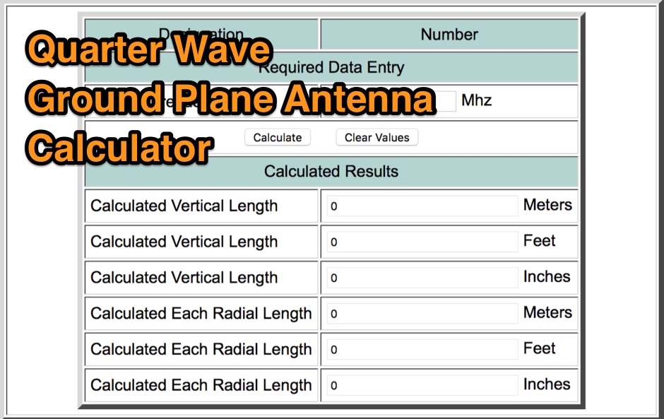 Amateur quarter wave ground plane antenna calculator, calculate vertical and radial length
 -
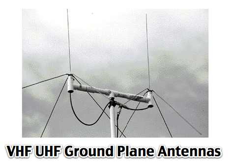 Phased array Ground Planes antennas for 144 Mhz
 -
 This antenna project came out very nice. It's a rugged homebrew multi-band trap vertical antenna that works the 10, 15, and 20 meter amateur radio bands. The antenna can be mounted on the ground or on a mast. Mounted on the ground the antenna has a low take off angle for working DX. If mounted on a mast the antenna will acheive both a low angle as well as another radiation lobe that has a much higher take off angle.
 -
 Inverted V antennas is a dipole with the center raised on a mast and the endpoints near ground. Calculate dimensions online.
 -
 Java script antenna calculators for ground planes, half wave verticals, quad antenna, 5/8th wave vertical antenna, dipole and inverted vee antennas
 -
 Constructing an HF End-Fed Half-Wave (EFHW) vertical antenna, the resource details the winding of a monoband matching unit, inspired by _AA5TB_, designed to provide a 50 Ohm impedance match without a ground plane or antenna tuner. It specifies the use of a _T200-2_ ferrite core for the transformer, outlining the 13-turn secondary and 2-turn primary winding process with enamelled copper wire. The document also describes the integration of a coax capacitor, whose length is critical for tuning and varies by band, with specific starting lengths provided for 20m, 17m, 15m, 12m, and 10m operation. The practical application section guides the builder through tuning the antenna using an antenna analyzer, emphasizing the iterative process of spacing secondary windings and trimming the coax capacitor to achieve resonance at the desired band frequency. It highlights the antenna's low angle of radiation, beneficial for DX, and claims up to 2 S-points improvement over a _G5RV_ or similar doublet when used as an omnidirectional vertical. A comprehensive shopping list, including specific part numbers from _Rapid Electronics_, is provided, along with advice on selecting fiberglass fishing poles for support and suitable antenna wire.
 -
 Wound on a 3 foot length of PVC pipe, the long loopstick antenna was an experiment to try to improve AM radio reception without using a long wire or ground.
 -
 The basic antenna is a vertical monopole, using elevated radials to complete the ground plane by k5oe
 -
 The total length of the inverted L is 240 feet, which is 7/16th of a wave length long. It has a 92 foot horizontal linear load section 1 foot above ground that terminates into a home-brewed parallel network tuner by KN4LF
 -
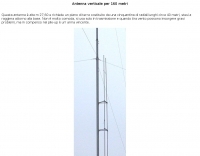 This high antenna require a large ground composed by 40 radials. It's not very handy expecially in windy situations but is very powerfull in pile-ups. In italian
 -
 End-Fed Half-Wave Antennas (EFHWAs) are analyzed for their utility in portable QRP operations, emphasizing their simplicity, efficiency, and predictable radiation patterns compared to other portable antenna types. The discussion contrasts EFHWAs with vertical antennas, random length wires, and center-fed dipoles, highlighting the common pitfalls of each, such as ground system dependency for verticals and feedline issues for dipoles. The article details the electrical half-wavelength calculation using the formula L (Ft) = 468/F(MHz) and explains how EFHWAs can be resonant on harmonic frequencies, enabling multiband operation. Various deployment configurations are presented, including the inverted L, inverted Vee, sloping wire, and vertical setups, each with specific advantages for radiation angle and polarization. For instance, a vertical EFHWA offers a low angle of radiation suitable for DX contacts without requiring an extensive ground system. The resource also addresses the counterpoise requirements, suggesting a quarter-wavelength wire or connection to a metallic structure for decoupling. A schematic diagram for a simple parallel-tuned circuit tuner, based on the _Rainbow Bridge/Tuner_ design, is provided, detailing component values for 30 and 40 meters, including a 6 microhenry toroidal inductor and a 20-100 picofarad mica compression capacitor. The tuner's adjustment process for SWR matching is also outlined.
 -
 This PDF document, authored by KT4QW in October 2004, details the construction and modeling of a dual-band, horizontally polarized hanging rectangular loop antenna for **10 and 17 meters**. The design, adapted from *The ARRL Handbook*, utilizes _NEC4WIN95_ software for scaling and optimization, targeting a 50 ohm feedpoint impedance. The resource includes a bill of materials, step-by-step construction instructions, and a discussion of the antenna's radiation characteristics. It presents NEC-generated elevation and azimuth patterns, comparing the loop's performance to a half-wave horizontal dipole at the same height and frequency. The 17-meter element is centered at 18.140 MHz for low SWR across the phone band, while the 10-meter element is centered at 28.500 MHz. Construction involves 14-gauge stranded copper wire and Schedule 40 PVC spreaders, with the total wire length calculated by the formula: Length in feet = 1005/MHz. The feedpoint impedance can be adjusted by modifying the rectangular aspect ratio. The document specifies hoisting the antenna to at least a half-wave above ground for testing. It notes that a balun was tested and found to have no measurable effect on SWR or radiation characteristics. A 2-meter scale model is presented to illustrate the physical design, and a "rotator" string is incorporated for directional adjustment up to 90 degrees.
 -
 There are many kinds of satellite antennas that will get you on the birds and allow you to have lots of fun