Search results
Query: igate
Links: 88 | Categories: 5
-
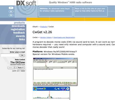 CwGet v2.55 is a software application for amateur radio operators designed to decode Morse code (CW) signals into text using a standard computer sound card, eliminating the need for specialized hardware. The program features a customizable interface with a spectrum display for visualizing signal frequencies and peaks, an oscillogram for monitoring signal presence and setting detection thresholds, and a received symbols window for displaying decoded text. Key functionalities include Automatic Frequency Control (AFC) to lock onto signals, adjustable FIR and IIR filters for noise reduction, and a burst filter to mitigate short noise impulses. It also supports automatic CW speed detection, multiple character sets, and the ability to record and replay received audio. Integration with logging software like AALog is facilitated through double-click word transfer, and transceiver frequency control is possible via the Omni-Rig interface, allowing for automatic tuning of the radio's VFO or RIT. The multi-channel decoder feature can simultaneously decode up to five strong signals within a 1600 Hz bandwidth, displayed in a separate Multi-RX Window with an adjustable squelch. CwGet also offers the capability to decode signals from pre-recorded WAVE files and can function as a narrow-band sound DSP filter for aural decoding. This is a commercial version and it has been tested on latest MS Winows versions.
 -
 This resource details the fundamental aspects of deploying longwire antennas, emphasizing ease of construction and installation for shortwave listening (SWL) and broadcast reception. It covers wire gauge selection, suggesting 14 to 24 AWG for general use, with heavier gauges (14-20 AWG) for permanent outdoor installations. Guidance is provided for various deployment scenarios, including indoor setups where the wire can be run around a room, temporary outdoor installations from balconies using light 18-24 AWG wire, and permanent outdoor configurations requiring higher placement and slack for tree movement. Feeding methods are discussed, recommending coaxial cable (50-75 ohms) to mitigate man-made interference, with instructions for connecting only the center conductor to the longwire. Safety precautions are highlighted, particularly avoiding contact with power lines and conductive materials, and managing static electricity buildup by unplugging the antenna after use and bleeding off charges before connection. The article also advises against using outdoor longwires during thunderstorms or snowstorms due to static and lightning risks. Optimal height considerations are presented, advocating for the highest safe placement, ideally a couple of feet above underlying structures, to maintain free air space. The text mentions a personal setup with one end at a roof peak (20 feet) and the other at a 17-foot mast, illustrating practical deployment without strict height requirements beyond safety and clearance.
 -
 A 9 dB gain 70cm collinear antenna construction is detailed, utilizing eight half-wavelength sections of _RG58/U_ coaxial cable. The design incorporates specific calculations for velocity factor (0.66 for RG58/U) to determine precise element lengths, such as 223mm for a half-wavelength at 444 MHz. A quarter-wave radiating element of #16 solid wire, 169mm long, is added to the top, and a 160mm aluminum tube acts as a quarter-wave counterpoise at the feed point. RF choke baluns, constructed from three _FT50-43_ toroids, are positioned a half-wavelength from the feed point to mitigate common mode current. Assembly involves soldering the coax sections in series, followed by SWR testing during construction and final mounting within a ¾-inch PVC pipe. The article suggests using four half-wave elements for a shorter antenna, noting a potential slight increase in SWR, which can be mitigated with quarter-wave ground radials. The design principles and formulas are scalable for other VHF/UHF bands like 6m, 2m, or 1¼m, providing a versatile homebrew solution for enhanced gain.
 -
 The G3TPW CobWebb antenna design provides a compact, horizontally polarized, omni-directional solution for 20m, 17m, 15m, 12m, and 10m bands. This antenna utilizes five full-size half-wave dipoles, each bent into a square configuration to achieve omni-directional radiation without the nulls typically found in straight dipoles. The design incorporates a single 50-ohm coaxial feedline with an integrated air-core choke balun, minimizing feeder radiation and reducing EMC issues. Construction details include using PVC-covered multi-stranded copper twin cable for elements, supported by a fiberglass cross. The document specifies tapping points for impedance matching to 50 ohms on all five bands, ensuring high radiation efficiency without lossy traps or loading coils. Physical dimensions are compact, with 2.6-meter (8.5 feet) sides and a total weight of 6 kg (14 lbs), making it suitable for mounting on a 20-foot aluminum scaffold pole. Detailed instructions for assembling the junction box, including terminal strip wiring and the coaxial choke balun, are provided with photographs and diagrams. The design emphasizes a confined electric field to reduce coupling to nearby conductors, which helps mitigate TVI and makes the antenna less sensitive to mounting height or ground conductivity.
 -
 Normal mode helix antennas offer a solution for HF mobile operators facing significant height restrictions, such as those parking in indoor garages with limited overhead clearance. This design, adapted from concepts typically applied to VHF/UHF rubber duck antennas, allows for extremely shortened HF radiators that remain effective for county hunting and general mobile operation. The resource details the construction of a 20-meter helix antenna, approximately 10 inches long, wound with #14 AWG THHN wire on a 1 1/2-inch CPVC form, mounted on a standard 3/8 x 24 antenna stud. Mark Herson, _N2MH_, shares his experience developing these antennas, including initial research from the _RSGB VHF UHF Manual_ and practical winding experiments to establish the relationship between turns and resonant frequency. He provides coil data for various frequencies, emphasizing that these measurements were taken with an _MFJ-259a_ antenna analyzer and are dependent on the vehicle's grounding system. Despite their shortened nature, N2MH confirms the antennas' operational effectiveness, citing contacts with KL1V in Alaska on 20 meters and E-skip contacts on 10 meters. The design prioritizes continuous deployment without removal, making it suitable for operators who frequently navigate height-restricted environments.
 -
 Constructing a compact, directional antenna for the 6-meter band presents unique challenges, especially for operators with limited space or those seeking portable solutions. This project details the build of a 50 MHz Moxon rectangle, specifically engineered for balcony or temporary mast deployment, using readily available materials from a typical hardware store. The design emphasizes ease of construction and portability, allowing for quick setup and breakdown. The antenna's dimensions are precisely calculated using _Moxgen_ software for 50.200 MHz, ensuring optimal performance. Key construction techniques include using aluminum U-channel for elements, fiberglass driveway markers for insulation, and cable ties for secure assembly. The guide provides detailed instructions for fabricating the driven element, reflector, and boom, including a clever method for creating foldable element tips for transport. Performance observations indicate a respectable front-to-back ratio, capable of reducing an S7 signal to S0 when pointed away, and a modest gain over a simple wire antenna. The design incorporates a ferrite bead choke balun at the feedpoint to mitigate common-mode current and reduce shack noise, a critical consideration for urban or apartment-based operations.
 -
 Demonstrates the construction and performance of an updated ZS6BKW multiband dipole, a variant of the _G5RV_ antenna, specifically designed for HF operation. The article details a real-world installation using 13.5m copper wire elements and 12.2m of 450 Ohm ladder line, configured as a sloping inverted-V with the apex at 10m and ends at 4m above ground. It covers the critical aspect of impedance matching, incorporating an 8-turn choke balun at the feedline transition to RG-58U coax to mitigate RF common mode current. Measurements confirm favorable SWR readings below **1.3:1** on 7.1 MHz, 14.11 MHz, 18.06 MHz, and 24.8 MHz, indicating effective resonance across 40m, 20m, 17m, and 12m bands. The installation also shows usable SWR dips on 3.55 MHz (5:1), 29.02 MHz (2:1), and 50.84 MHz (3:1), extending its utility to 80m, 10m, and 6m with an antenna tuning unit. Initial on-air results report clear reception of stations over **5000km** away, validating its DX potential.
 -
 QTH.COM offers a comprehensive platform for amateur radio enthusiasts to buy, sell, and trade equipment. This online service is designed to facilitate transactions between hams, allowing users to list their gear for free. Whether you're looking for HF or VHF equipment, antennas, or even vintage radios, QTH.COM serves as a hub for all your ham radio needs. The site is user-friendly and accessible, making it easy for both seasoned operators and newcomers to navigate the listings. In addition to individual sellers, QTH.COM also attracts dealers and manufacturers looking to reach a wider audience. With a diverse range of categories, including military radios and radio tubes, users can find unique items that may not be available elsewhere. The platform's commitment to providing a free service ensures that all hams can participate in the marketplace without financial barriers. Join the community at QTH.COM and discover the best deals in the ham radio world.
 -
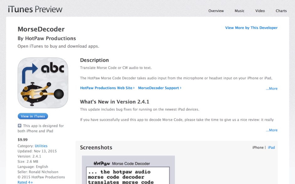 HotPaw MorseDecoder, an iOS application, provides real-time translation of Morse Code audio signals into plain text, leveraging the device's microphone or headset input. It incorporates a DSP narrow-band audio filter, adjustable from 300 to 2400 Hz, to mitigate background noise and QRM, enhancing signal clarity for decoding. The application offers both an automatic decoding mode and manual controls for fine-tuning parameters such as audio filter frequency, WPM dot/dash speed, noise threshold, and Farnsworth timing. The WPM detection automatically adapts from 8 to 40 WPM, with a QRQ High Speed mode extending this range to 30-80 WPM for faster code. A built-in spectrogram aids in identifying the precise audio frequency of the CW tones. User feedback indicates effective performance with various transceivers like the Yaesu FT-857 and Icom IC-R8600, particularly when manual settings are optimized. The app's ability to visually tune stations within the passband and decode speeds beyond an operator's manual capability has proven beneficial during contests and general QRP operation.
 -
 An antenna does not have to be resonant to work, as the primary reason for resonance is to eliminate the need for an impedance-matching device. A non-resonant wire dipole fed with open-wire line and an antenna tuner can function as an effective multiband antenna. Two wires are essential for powering an antenna, ideally with a balanced configuration like a dipole fed by parallel-wire line, though coaxial cable can be used with a 1:1 balun to mitigate RF feedback on the shield. Antenna gain is achieved by shaping and aiming RF energy, concentrating it in a particular direction, as seen in beam antennas or shaped radiation patterns of wire antennas. The function of an antenna tuner is to match the transceiver's 50 Ohm output to the antenna system's impedance, which can vary widely. Wire antennas do not always require center feeding; end-fed long wires or off-center-fed dipoles (Windom antennas) can be used, often requiring a counterpoise or radial system. Dipole antennas do not need to be perfectly horizontal; their legs can be bent, inclined, or even vertical, affecting feed point impedance. Vertical antennas shorter than a half wavelength necessitate a ground system, typically comprising radial wires, with more radials generally leading to greater efficiency. A 1:1 SWR indicates an impedance match but does not guarantee a good antenna, as an inefficient antenna with a poor ground system can still show a perfect SWR while wasting RF as heat. Always using the best feed line affordable is crucial for minimizing loss and maximizing RF signal delivery to and from the antenna.
 -
 The purpose of this web page is to try to investigate the ICOM IC-746PRO Dead TX problem reported by many radio amateurs through out the world; and unfortunately not properly taken care of by ICOM. If you are the owner of either the ICOM IC-746PRO or the IC-7400 you may already have experienced the Dead TX Issue. If not you may sooner or later.
 -
 Dire Wolf is a software soundcard modem and APRS encoder/decoder. It can be used stand-alone to receive APRS messages, as a digipeater, APRStt gateway, or Internet Gateway (IGate). It can also be used as a virtual TNC for other applications such as APRSIS32, UI-View32, Xastir, APRS-TW, YAAC, UISS, Linux AX25, and many others.
 -
 The W1TAG LF Receiving Loop is a specialized antenna project for LF reception, designed to mitigate local noise and enhance weak signal pickup on the lower frequencies. This square loop, measuring 6 feet per side, utilizes 14 turns of #12 THHN wire wound on a PVC frame, offering a robust mechanical structure. The design incorporates a series-tuned circuit with a coupling transformer, allowing for tuning from over 400 kHz down to _45 kHz_ using a switched capacitor bank. Construction details include the use of 1.5-inch PVC pipe for the frame, with specific measurements for spreaders and drilled holes for wire threading. The two 7-turn sections of wire are connected at the center, providing an option for a center tap. The loop rotates on a 1-inch steel pipe, enabling directional nulling of noise sources. The tuning unit, housed in a box clamped to the PVC, employs a 1:2 step-up transformer wound on an _FT-82-77 core_ and uses relays to switch capacitance values from 50 pF to 6400 pF, providing precise frequency adjustment. The current setup connects to the shack via 100 feet of RG-58, feeding into a W1VD-designed preamp, with plans for a balanced, shielded twisted pair cable upgrade.
 -
 A GSM1800 Moxon Square antenna project is presented, detailing its construction using three 1.5mm copper wire pieces for the reflector and dipole elements. The design inherently offers a 50-ohm feedpoint impedance, allowing direct connection to 50-ohm coax without complex matching networks like baluns or gamma matches, which are prone to high attenuation at 1.8 GHz if not precisely built. The resource includes a construction plan, expected **SWR plots**, and **radiation patterns** for the GSM 1800 band, specifically covering the 1710-1785 MHz transmit (red zone) and 1805-1880 MHz receive (blue zone) segments. The SWR remains below 2:1 across the entire GSM 1800 band, with the main lobe consistently achieving 5-6 dBi gain. While the radiation pattern shows some changes across the band, these primarily affect the back of the antenna, maintaining consistent forward gain. Practical considerations for high-frequency operation are emphasized, such as minimizing coax length (e.g., under 1 meter for RG-174) and selecting appropriate connectors like N, SMA, or BNC to mitigate significant attenuation. The article also discusses direct connection to the phone's RF PCB for minimal loss and notes observed signal strength variations with antenna orientation despite crossed polarization at cell sites.
 -
 The G5RV multiband HF antenna, designed by Louis Varney (G5RV) in 1946, is a popular compromise antenna offering good overall performance on most HF bands when paired with an external antenna tuner. The basic full-size G5RV measures 102 feet across the top for 80 through 10 meter operation and is fed at the center via a 34-foot low-loss feed-stub. This interaction between the radiating section and the feed-stub facilitates matching across 80-10 meters with a standard tuner, often eliminating the need for ladder line directly to the shack. The antenna's design center frequency is 14.150 MHz, configured as a 3/2-wave dipole on 20 meters, with its 102-foot length derived from long-wire antenna formulas. Construction details emphasize the matching section, which can be open wire, ladder line (window-type), or TV twin lead. Each type has a specific velocity factor (VF) affecting its physical length for an electrical half-wave on 14 MHz; for instance, open wire requires 33.7 feet (VF 0.97), ladder line 31.3 feet (VF 0.90), and TV twin lead 28.5 feet (VF 0.82). The article provides formulas for calculating these lengths and discusses the antenna's behavior on individual bands, from 3.5 MHz where it acts as a shortened dipole, to 28 MHz where it functions as two three-half-wave long-wire antennas fed in-phase. Practical construction notes include recommendations for vertical descent of the matching section, sealing the coax junction, providing strain relief, and winding a coaxial choke coil to mitigate common mode current. The resource also presents dimensions for double-size (204 ft) and half-size (51 ft) G5RV versions, along with their corresponding matching section lengths for various line types, making it a versatile reference for hams considering this classic wire antenna.
 -
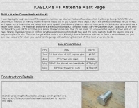 The resource details the construction of a **Hustler-compatible** HF mobile antenna mast, utilizing 1/2-inch copper water pipe and common hardware. It provides a bill of materials, specifying one 10-foot copper pipe, four 1/2-inch copper end caps, and 3/8-inch fine-thread hex bolts and nuts, totaling $8.75 for two masts. The construction process outlines preparing bolts by rounding their heads, drilling 3/8-inch holes in end caps, soldering bolts into caps, and then soldering these cap/bolt assemblies to 5-foot sections of copper pipe to achieve a final length of 54-1/4 inches per mast. The method emphasizes precise soldering techniques to ensure structural integrity and proper fit. The resulting masts are presented as functional alternatives to commercial units, with the author noting their performance is comparable to the "real thing." Installation tips are provided, including the use of braces connected to a trunk lid to mitigate stress on the antenna mount, contrasting this approach with WA8WTE's spring-based method. Photos illustrate the completed mast mounted on a vehicle, demonstrating practical application and support strategies for mobile HF operation, particularly with larger coils and longer whips at highway speeds.
 -
 Industrial Communication Engineers (ICE) was a manufacturer specializing in **RF components** and solutions for amateur radio and commercial applications. Their product line included a range of RF parts, various types of filters, and RF switching products designed to enhance station performance and mitigate interference. These components were critical for hams engaged in contesting, DXing, or general operating, providing means to improve signal integrity and manage complex antenna systems. The company's offerings addressed common operational challenges such as RFI and TVI, with products like **low pass filters** and antenna filters. While the specific technical specifications of their product range are no longer available, such components typically provided significant attenuation of unwanted harmonics and out-of-band emissions, crucial for maintaining a clean signal and preventing interference with other electronic devices. The current status indicates the domain is for sale, suggesting the manufacturing operations have ceased.
 -
 A 6 dB gain Moxon rectangle antenna, designed for the 2-meter band, offers an excellent solution for hams seeking a compact, directional antenna for **SSB** operation, particularly in restricted spaces like an attic. This design emphasizes ease of construction using readily available materials such as 4mm OD brass tubing and plywood, making it an accessible project for many radio amateurs. The antenna's inherent characteristics, including a high front-to-back ratio of 37 dB and a 50-ohm feed impedance, contribute to its effectiveness in mitigating local noise and focusing radiated power. The project leverages the free MoxGen program for precise dimension calculations based on the desired frequency and wire size, and utilizes 4nec2 for pattern analysis, confirming a 3 dB beamwidth of 80 degrees. Construction involves bending brass tubing for the driven and passive elements, mounting them on an 800 x 350 mm plywood boom, and securing them with cable clips and epoxy resin. Initial SWR measurements at 144.3 MHz showed 1.6:1, which improved to 1.3:1 at 145.3 MHz across a flat band from 144.1 MHz to 145.5 MHz after adding a **coaxial choke** to mitigate common mode current.
 -
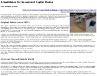 The Elecraft K2 transceiver requires specific modifications for optimal soundcard digital mode operation, particularly for PSK31. The original article, circa 2001, details initial challenges with manual PTT and speech compression settings. A key modification involves adding headphone audio and a compression disable signal to the K2's microphone jack, utilizing pins 4 and 5. The **COMP0** signal, active low, is shorted to ground via a non-inverting open collector switch circuit, comprising two resistors and two transistors, mounted on the SSB board near U3. This circuit provides effective control of an analog signal line with good noise immunity. The switchbox itself repurposes a computer COM port switch, using only two of its original connectors and four of the nine poles. It integrates a microphone preamplifier, a PTT circuit built with 'flying leads' construction, and RCA jacks for soundcard connections. A trimpot adjusts the audio drive to the K2. The central DB9 connector links to the K2's mic connector via a shielded RS232 serial cable, ensuring proper grounding and signal routing. An external footswitch PTT jack is also included. Further enhancements include a **noise-canceling microphone** preamp based on a QST December 2000 article, adapted for Heil mic elements. This preamp, built with pseudo-Manhattan style construction, provides a gain of approximately 2 by changing emitter resistors (R9 and R16) from 680 ohms to 330 ohms. A 10-ohm series resistor and 47 µF capacitor on the +5V supply mitigate noise spikes.
 -
 This resource details the four primary functions of a ground system: lightning energy dispersion, equipment safety, RF return path provision for end-fed antennas, and management of induced RF currents. It clarifies that a ground system's effectiveness varies depending on its specific function, noting that a good lightning ground might not be an effective RF ground. The content emphasizes that proper antenna system design, including baluns and appropriate feedline lengths, often negates the need for an RF station ground to mitigate common mode currents or RFI in the shack. The article quantifies lightning energy, stating its peak is in the dozens or hundreds of kilohertz, with damaging energy extending to hundreds of megahertz, and currents reaching thousands of amperes. It recommends solid, wide, smooth copper surfaces for ground leads to achieve low impedance across a wide frequency range. The author, W8JI, shares practical insights from his station, which includes two 300-ft towers and four 130-ft wire verticals, detailing his use of common point grounds and _DX Engineering RR-8 HD_ antenna switches for lightning protection without coaxial surge protectors. Specific examples of antenna systems prone to common mode current problems are listed, such as random wire antennas without proper feedline lengths and off-center fed dipoles. The text also explains how a ground screen or radial system can reduce local noise sensitivity for vertically polarized antennas by covering the lossy earth.
 -
 The purpose of this web page is to try to investigate some of the issues around ICOM IC-746PRO reported by many radio amateurs through out the world; and unfortunately not properly taken care of by ICOM.
 -
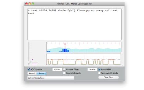 The HotPaw Morse Code Decoder application for macOS processes audio input to transcribe Morse code characters into text. It presents both an audio spectrum graph and a tone amplitude graph, which aid in configuring a narrow band audio filter. Operators can set the audio filter for tone frequencies between 400 and 1600 Hz, optimizing reception for various CW signals. The software offers user-configurable settings, including WPM dot/dash speed detection, a noise threshold level, and the option to use Farnsworth timing for inter-character spacing. The Morse code WPM detection automatically adapts from approximately 8 to 40 WPM, with a lock feature for the estimated speed. A High Speed WPM Mode is available for code speeds ranging from 40 to 80 WPM, catering to faster CW operators. The application's decoding performance is influenced by signal level, signal-to-noise ratio, frequency and WPM stability, keying quality, and proper configuration, with an initial learning phase required for WPM estimation to stabilize. An external microphone or line-in may be necessary for optimal performance on some MacBook models to mitigate fan noise or room reverberations. Version 1.4.4, updated on November 11, 2021, includes compatibility improvements for newer macOS releases. The developer, Ronald Nicholson of HotPaw Productions, does not collect any user data from the application.
 -
 Ten essential tips and truisms for understanding HF antenna: Non-resonant wire dipole antennas fed with open-wire line and an antenna tuner can function effectively as multiband antennas, as detailed in "The Classic Multiband Dipole Antenna" by WB8IMY in March 2004 QST. Coaxial cable, unlike balanced parallel-wire feed lines, can cause RF to travel on the outer shield braid, leading to RF feedback to the station; a 1:1 balun at the dipole center can mitigate this by isolating the unbalanced coaxial feed line. Antenna gain is achieved by shaping and directing RF energy, with beam antennas concentrating power in a specific direction, and wire antennas also exhibiting shaped radiation patterns. An antenna tuner's primary role is to match the transceiver's 50-ohm output to the antenna system's impedance, allowing modern transceivers to deliver full power. Wire antennas do not always require center feeding; end-fed long wires or off-center-fed dipoles (like the Windom) can be used, though they often necessitate an antenna tuner and a counterpoise or radial network. Dipole antennas do not need to be perfectly horizontal; their legs can be bent or inclined, which affects feed point impedance and may require SWR experimentation with coaxial feed. Vertical antennas shorter than a half wavelength require an efficient ground system, typically comprising elevated or buried radial wires, with more radials generally leading to better efficiency. A 1:1 SWR indicates an impedance match but does not guarantee antenna efficiency; an inefficient vertical antenna with a poor ground system can show a low SWR while wasting most RF as heat. Investing in high-quality, low-loss feed line, especially coaxial cable, is crucial for maximizing RF signal transfer and overall antenna system performance.
 -
 For over 20 years, bhi Ltd has specialized in digital signal processing (DSP) technology to mitigate noise and interference across various radio channels. Their product line, including the _ParaPro EQ20 Audio DSP_ units, focuses on enhancing receive audio quality, even for operators without significant noise issues, by offering precise parametric equalization to suit individual hearing preferences. The core offerings are noise-cancelling speakers and in-line modules, specifically engineered for amateur radio applications, but also adapted for commercial, PMR, and marine radio systems. The company provides audio demonstrations, such as a 20m SSB example and a 14MHz band filter comparison, allowing users to hear the effectiveness of their DSP units against common QRM sources like plasma TV interference or diesel engine noise. Located in Burgess Hill, West Sussex, UK, bhi Ltd emphasizes clear voice communications, aiming to remove unwanted noise and leave only intelligible speech.
 -
 A 200 kHz bandwidth digital transmission system for image transfer in the Amateur Service is under development, specifically targeting VHF allocations. John B. Stephensen, KD6OZH, leads this project under an FCC Special Temporary Authority (STA) valid until September 10, 2006, authorizing emissions up to 200 kHz bandwidth in the 50.3-50.8 MHz segment. Current regulations typically limit bandwidths to 20 kHz on VHF amateur bands, making this STA crucial for testing wideband digital modes. The modem, a modified **OFDM** (Orthogonal Frequency Division Multiplexed) unit, was initially tested on the 70-cm band. It splits a high-rate data stream into multiple low-rate subcarriers to mitigate multipath echoes. The system uses a DCP-1 card with a Xilinx XC3S400 FPGA and Oki Semiconductor ML67Q5003 microcontroller. The transmitter, located at 36d 46m 30s N, 119d 46m 22s W, generates 150 WPEP into an 8 dBi gain vertical antenna, while the mobile receiver uses a Ham-stick. Three data formats for 50, 100, and 200 kHz channels are being tested, with encoded data rates of 96, 192, and 384 kbps. Verilog code for the VHF OFDM modem is 95% simulated, with modifications from the UHF version including increased filter coefficient precision and a change from Ungerboeck **TCM** to BICM for improved performance over fading paths. Final tests will involve one-way over-the-air measurements of bit error rates and coverage area.
 -
 Details the construction of an **HF converter** designed by M1GEO, George Smart, specifically to extend the frequency range of the FunCube Dongle Pro (FCD) for amateur radio reception. The FCD natively covers 64 to 1,700 MHz, but this project enables reception from 0 Hz to 64 MHz by up-converting signals to the FCD's operational range. It employs a **double-balanced mixer** with a 100 MHz local oscillator (LO) to translate incoming HF signals; for instance, a 1 MHz signal appears at 101 MHz within the FCD's passband. The design incorporates a 7th-order Chebyshev low-pass filter with a 62 MHz cutoff frequency at the input to mitigate image frequencies, ensuring cleaner spectral presentation. George provides the schematic, PCB masks, and Gerber files for replication, noting that Far Circuits also offers PCBs. The resource includes test results for the low-pass filter and measurements of LO leakage, identifying -36.8 dBm at 100 MHz as a potential sensitivity concern. M1GEO discusses potential improvements, such as adjusting the mixer's LO drive, adding a balance pot, or incorporating a post-mixer high-pass filter to reduce LO breakthrough. Audio recordings from 40m and 17m demonstrate the converter's performance with WRplus SDR software.
 -
 This resource provides fundamental guidelines for optimizing mobile amateur radio antenna installations. It addresses critical factors such as achieving an adequate ground plane, minimizing common mode current, and reducing ignition noise. Specific recommendations include mounting antennas on the vehicle's roof for superior radiation patterns and utilizing proper feedline routing to mitigate RF interference within the vehicle's electrical system. The content details the impact of antenna placement on Standing Wave Ratio (SWR) and overall radiated power, emphasizing the importance of a solid electrical connection to the vehicle chassis. It also discusses strategies for noise suppression, such as bonding body panels and employing ferrite chokes on power leads. The information presented is practical for hams seeking to improve their mobile station's efficiency and reduce RF-related operational issues.
 -
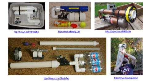 Investigates the legal framework surrounding **pneumatic antenna launchers** in Victoria, Australia, specifically their classification under the Firearms Act 1996. The author, VK3KBC, details how these devices, designed to discharge a projectile by compressed air, are defined as 'firearms' and subsequently categorized as **Category E Longarms**. This classification carries significant penalties for unregistered possession or use, with the author noting the lack of provisions for amateur radio operators to legally possess and use such devices for antenna deployment. The author shares personal experiences needing such devices for portable HF radio operations, contrasting them with previously legal slingshots and current alternatives like kites or bow and arrow. VK3KBC outlines efforts to advocate for legislative change, including submissions to the Wireless Institute of Australia (WIA) and the Victorian Department of Justice, proposing an amendment to Section 3(i) of the Firearms Act 1996 to include amateur radio field operations as an exempted use. The resource also reviews the original intent of the Category E firearm classification, suggesting that pneumatic antenna launchers may have been assigned this category in the absence of a more suitable alternative.
 -
 The purpose of this web page is to try to investigate some of the issues around ICOM IC-746PRO reported by many radio amateurs through out the world; and unfortunately not properly taken care of by ICOM.
 -
 How to navigate FlexRadio PowerSDRs Pan Adapter
 -
 Mobile RFI, often manifesting as persistent noise in the receiver even with the antenna disconnected, frequently originates from the vehicle's power supply system. This guide details systematic troubleshooting steps, beginning with isolating the radio from the car's 12-volt supply to confirm the power system as the noise source. It emphasizes the critical importance of drawing power directly from the battery using **heavy gauge wire**, bypassing the fuse block to leverage the battery's natural capacitance for RFI suppression and ensuring a solid RF ground. Proper routing of power lines through the firewall is also covered, advocating for dedicated grommeted holes to prevent inductive coupling from other wiring harnesses. The article stresses the necessity of fusing both positive and negative leads from the battery, a crucial safety measure to prevent damage to the rig and mitigate high-current risks should the battery's engine block ground become compromised during service. Addressing **alternator whine**, a common high-pitched noise that varies with engine speed, the resource suggests checking battery connections and the alternator-to-battery harness for looseness or corrosion. It also mentions the utility of adding an external RF noise suppression capacitor in parallel with the alternator's internal capacitor for enhanced filtering, and the effectiveness of commercially available in-line power supply filters.
 -
 This resource compiles claimed scores, often referred to as "rumor scores," for numerous amateur radio contests, providing a historical snapshot of competitive activity from 1993 through 2007. It lists entries for prominent events such as _CQWW CW_, _ARRL Sweepstakes_, _IOTA Contest_, and various _NAQP_ events, categorized by year and contest. Each entry typically includes the contest name and the month/year of operation, allowing users to quickly navigate to specific contest periods. The site also references the _3830 Web Page_ on Contesting.com as the primary submission portal for these claimed scores. The collection offers a unique perspective on contest participation and performance trends over more than a decade, preceding the widespread adoption of real-time score reporting systems. While not official results, these rumor scores provided early indications of top performers and overall activity levels for a wide array of HF and some VHF contests, including _ARRL 10M_ and _CQWW VHF_. The historical data can be useful for analyzing past contest popularity, identifying consistently strong operators, or simply reminiscing about earlier competitive eras in amateur radio.
 -
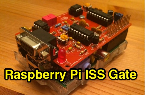 This project is an APRS iGate for digipeater aboard the ISS. As the ISS pass over the iGate location, the TNC decoded the audio tones and creates data packets the Raspberry Pi can receive.
 -
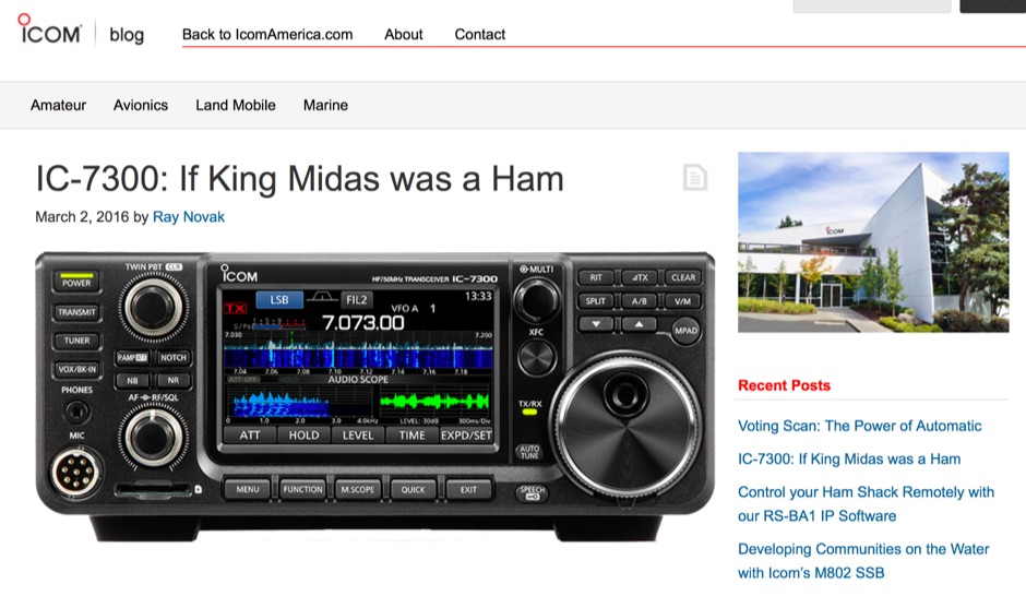 The Icom IC-7300 is a groundbreaking Software Defined Radio (SDR) transceiver that revolutionizes the way amateur radio operators interact with the spectrum. With its large 4.3-inch color TFT LCD touch screen, users can easily navigate through various functions, including real-time spectrum scope and high-resolution waterfall displays. This allows for quick adjustments and enhanced signal awareness, making it easier to find and engage in QSOs. The touch screen interface provides a modern approach to radio operation, replacing traditional buttons with virtual controls that can be accessed with a simple touch. In addition to its user-friendly interface, the IC-7300 boasts advanced features such as IF-DSP filtering, audio scope functions, and a multi-dial knob that combines tactile control with touch screen flexibility. These capabilities enable operators to visualize signals and make precise adjustments to their settings, ensuring optimal performance during contests or casual operating. The IC-7300 is designed for both beginners and experienced hams, making it a versatile addition to any shack. Its innovative design and functionality truly embody the spirit of modern amateur radio.
 -
-
 This resource provides a discussion group platform for amateur radio operators interested in APRS within Argentina. It facilitates technical discussions, sharing of operational experiences, and coordination among users of the Automatic Packet Reporting System in the region. The group serves as a central point for exchanging information on local digipeater networks, IGate deployments, and mobile tracking applications, covering both hardware and software aspects relevant to APRS implementation. The forum enables members to post questions, offer solutions, and disseminate news related to APRS activities specific to Argentina, fostering a community-driven approach to problem-solving and knowledge transfer. It supports the collaborative development and maintenance of the APRS infrastructure, allowing for real-time interaction on topics such as frequency usage, network topology, and integration with other amateur radio services.
 -
 The VU2BBB repeater, located in Matheran, Maharashtra, commenced operations in the late 1980s, a significant undertaking by the Bombay Repeater Society. This repeater facilitates VHF and UHF communications for local amateur radio operators, providing extended range and improved signal reliability across challenging terrain. Its establishment marked a key development in regional amateur radio infrastructure, offering a crucial node for local nets and general QSO traffic. The repeater's operational parameters include specific input and output frequencies within the 2-meter band, typically utilizing a standard offset. CTCSS tones are often employed to mitigate interference and ensure selective access for authorized users, a common practice for repeaters in densely populated areas. Regular maintenance and upgrades ensure _VU2BBB_ remains a reliable asset for the amateur community, supporting emergency communications and daily amateur radio activities. The _Bombay Repeater Society_ continues to oversee its operation, reflecting a sustained commitment to local ham radio services.
 -
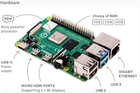 This resource is an online tutorial focused on setting up the Raspberry Pi for amateur radio applications. It covers the installation and configuration of various software packages tailored for digital communications and protocols, including _Packet Radio_ with Hamlib and Direwolf, as well as data modes like FLDigi and WSJT-X. The guide also details the integration of hardware components such as GPS clocks for time synchronization and real-time clocks for enhanced functionality. Users will find instructions for installing software like GPredict for satellite tracking and GQRX for software-defined radio (SDR) applications. The tutorial emphasizes practical steps, including the use of command-line inputs in the Raspberry Pi OS terminal, and provides troubleshooting tips for common issues such as faulty SD cards or insufficient power supplies. Operators are encouraged to explore various applications, including APRS iGates and WSPR beacons, to enhance their ham radio experience. The material is designed for licensed amateur radio operators with basic knowledge of electronics and computing.
 -
 An Google Maps interactive layer showing Australian amateur radio repeaters. You can navigate and zoom as required and click on a repeater-site icon to display frequency, ctcss and other details and notes for that repeater.
 -
 The interactive Smith chart enables users to navigate their way around a Smith chart, using simple discrete element impedance matching. This page allows users to try using the Smith chart, for education and interest purposes, without installing any software. Try changing the value in the load box to see the location of the impedance on the chart.
 -
 The 3Y0K website is the official platform for the Bouvet Island DXpedition scheduled for February 2026. It serves as a comprehensive resource for amateur radio operators, providing essential information about the expedition, including updates on operations, band availability, and communication modes such as FT8 and CW. The site aims to keep the amateur radio community informed about the expedition's progress and activities, encouraging participation and support. Users can find details on how to donate to the expedition and contact information for inquiries, as well as links to social media for real-time updates and community engagement. In addition to operational details, the 3Y0K site offers various resources for those interested in DXpeditions. It highlights the significance of Bouvet Island as a rare DXCC entity and outlines the logistical challenges faced by the team. The website is designed to be user-friendly, featuring a clear layout that allows visitors to navigate easily through the information. Overall, the 3Y0K website is a valuable resource for amateur radio operators looking to engage with the Bouvet Island DXpedition and enhance their understanding of amateur radio operations.
 -
 Demonstrates the practical application of APRS (Automatic Packet Reporting System) through the lens of HB9PVI's activities in Switzerland. It covers the system's core function of reporting geographical positions and telemetry data from various objects, including mobile stations, aircraft, and the ISS, distributed via packet radio and internet gateways. The resource highlights the routing paradigm shift introduced in April 2005, specifically the recommendation to use _WIDE1-1_ instead of RELAY and WIDE for digipeating to reduce duplicate packets. The page presents real-time maps displaying the positions of amateur radio stations in Switzerland and around Bern, updated every few minutes. It details specific callsigns like _HB9BA-2_ (HB9PVI's home QTH), _HB9BA-8_ (a weather station), and _HB9BA-4_ (a WIDE digipeater on Weissenstein mountain), providing context for their roles within the local APRS network. Links to track HB9PVI's mobile operations (_HB9PVI-9_) and handheld devices (_HB9PVI-15_, _HB9PVI-7_) are also provided. Furthermore, the resource curates a list of APRS software options for various operating systems, including _JavAPRS_ for Europe, _UI-view_, and _X-Astir_ for Linux, alongside digipeater/IGATE software like _DiXPRS_. It also offers downloadable APRS information, including a PDF article by HB9PVI and HE9ZGN, and a PowerPoint presentation in German, making it a repository of practical and historical APRS data.
 -
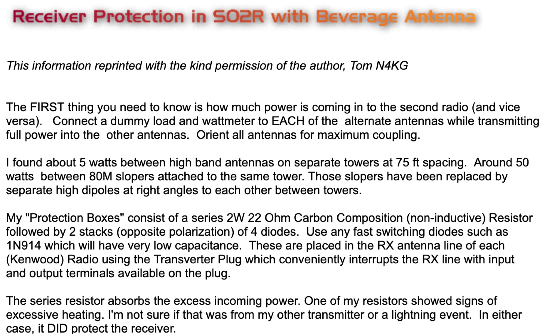 Operating in a Single Operator Two Radios (SO2R) setup, especially with beverage antennas, often exposes the receiving radio's front-end to significant RF energy from the transmitting radio. This resource details a practical, homebrew receiver protection circuit designed to mitigate this risk. The core of the design involves a non-inductive 2W 22 Ohm carbon composition resistor in series with the RX antenna line, followed by two stacks of four fast-switching diodes (e.g., _1N914_) configured in opposite polarizations. This arrangement effectively clamps the incoming voltage to approximately 2.8 V peak-to-peak, safeguarding sensitive receiver input components. The series resistor plays a crucial role by absorbing excess power, preventing the diodes from exceeding their current ratings and potentially failing open, which would leave the receiver unprotected. The author, _N4KG_, measured up to 50 watts of coupled power between 80M slopers on the same tower, highlighting the necessity of such protection. The design is presented as a cost-effective solution to prevent damage to receiver input transformers, with the author noting successful protection of a receiver even after a resistor showed signs of overheating. This simple circuit can be integrated via a transverter plug, offering a robust defense against high RF input.
 -
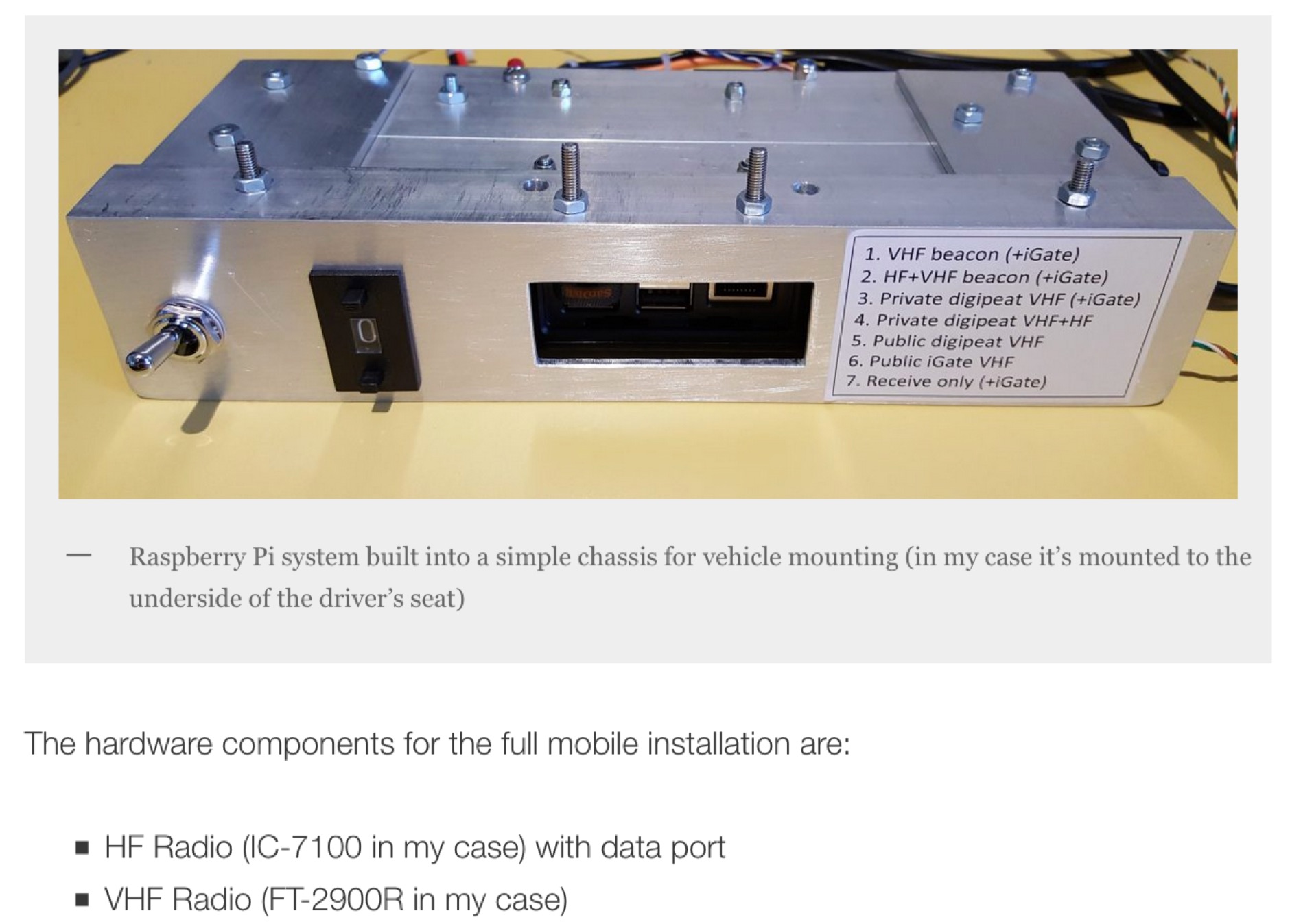 A project to turn a Raspberry Pi into a very versatile tracker, digipeater and an iGate
 -
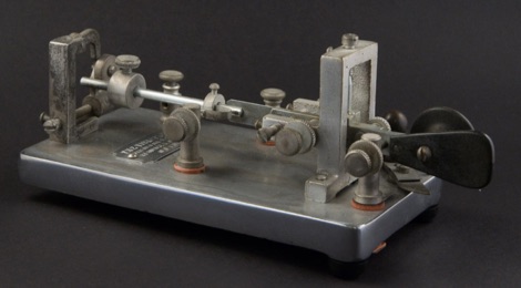 The Vibroplex Collector’s Page details the history and identification of Vibroplex semi-automatic telegraph keys, commonly known as "bugs." It traces the evolution from Horace G. Martin's 1902 Autoplex, which required a battery, to the fully mechanical Vibroplex patented in 1904. The resource explains how these keys generate automatic dots and manual dashes, helping telegraphers mitigate Repetitive Motion Disorder (RMD) and increase sending speed, thus improving their earnings. The site also covers the initial design by Alfred Vail in 1844, Jesse Bunnell's 1881 "Triumph Key," and William O. Coffe's 1904 "Mecograph." This page assists owners in identifying their Vibroplex models and determining their manufacturing dates, providing insights into the company's long history and notable figures like J. E. Albright. It notes that approximately 300,000 Vibroplexes have been produced since 1904, with the Original model still in production after more than 90 years. The resource also touches upon various Vibroplex models, including unusual, scarce, and common types, alongside legal and illegal clones from other manufacturers.
 -
 DL7JV shares his practical experience building and testing capacitive antennas, initially skeptical of their performance compared to magnetic loops and mono-band dipoles. His interest was piqued after hearing a Spanish station running 100 Watts on 80 meters with a 1-meter Micro Vert, making DX contacts into PY and UA0, despite the antenna being only 4 meters high in a garden. This prompted DL7JV to investigate further, consulting resources from DL7PE and DL7AHW, the latter providing DOS programs like "Mitspule.exe" and "Spulenprg.zip" for calculating antenna dimensions and coil conversions. The article outlines the construction of two prototype antennas: one for 7.050 MHz using a 75mm PVC pipe and another for 3.550 MHz with a 110mm PVC pipe. Both designs feature aluminum foil condensers and coils wound from 1mm² H07V-K wire. DL7JV provides specific measurements for the condenser capacitance, surface area, diameter, height, coil inductance, turns, and wire length for both 40m and 80m versions, along with RG58 feedline lengths. Initial reception tests for the 7 MHz antenna, placed indoors, yielded impressive S9+5 signals from a German station compared to an S8 from a 42-meter roof-mounted loop, even hearing a Japanese station. Transmission attempts on April 4, 2004, despite moderate solar storm conditions, resulted in successful QSOs on 7 MHz with EA5OT (579/559) and on 3.5 MHz with YT1NT (579/559) and G4KKI (579/559) using 100 Watts. DL7JV notes the antenna's sensitivity to coordination and feedline layout, suggesting a modification from DL7AXO involving a 500pF fixed capacitor and coil tap for improved SWR stability. He concludes that while the capacitive antenna is space-saving and performs well for reception and 100W transmission indoors, its transmit performance doesn't yet match larger antennas, with further outdoor field tests planned. DL7JV also intends to build a 1.8 MHz version.
 -
 This practical, hands-on article offers a valuable journey through balun construction for portable antenna systems. The author skillfully navigates from theoretical debates to practical implementation, providing a well-documented DIY process using RG316 micro coax and an FT114-43 toroid core. The step-by-step instructions, complemented by photographs, make this complex technical project accessible to hobbyists. Particularly impressive is the author's focus on lightweight design (just 173 grams) for SOTA field operations. While the final antenna requires minor tuning adjustments, the successful field test during the Pirate Contest demonstrates the effectiveness of this approach. An excellent resource that transforms theory into practical application for ham radio operators.
 -
 Documents the XR0ZR DXpedition to Juan Fernandez Island (SA-005) in November 2013, providing insights into activating a highly sought-after DXCC entity. The team's efforts focused on maximizing QSO opportunities across various bands and modes, a critical aspect for stations aiming to complete their DXCC or IOTA awards. Operating from a remote location like Juan Fernandez presents unique logistical and technical challenges, which the expedition successfully navigated to put this entity on the air for thousands of eager DXers worldwide. The resource outlines the operational period, the callsign XR0ZR, and the specific island group activated. Such DXpeditions are vital for the global amateur radio community, enabling hams in less accessible regions to achieve their award goals and fostering international communication. The detailed account serves as a historical record of a significant activation.
 -
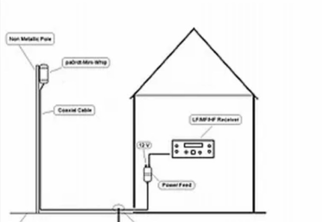 The author investigated electric field antennas and achieved promising results with a shortened active whip antenna (30 cm). The findings suggest that at LF, active whips function primarily through electric field capacitance coupling.