Search results
Query: linear rf
Links: 46 | Categories: 2
-
 The G5RV antenna, with an overall length of **31.10m (102ft)**, functions as a 3/2-wave on 20 meters when installed horizontally at 12m (39ft), exhibiting a resonant frequency of 14.150MHz and an approximate resistance of 80 ohms. Its 10.36m (34ft) stub line, designed as a 1/2-wave on 14.150MHz with a 0.97 velocity coefficient, acts as an impedance transformer across other bands, aiming for multiband operation without traps. On 20m and higher frequencies, the G5RV demonstrates improved gain compared to a standard dipole, attributed to the _collinear effect_ from multiple 1/2-waves along the wire. The original design sought a multiband solution for limited spaces, often requiring an Antenna Tuning Unit (ATU) for effective operation across bands like 80, 40, 30, and 20m, particularly with modern solid-state PAs. Variants, such as the F8CI modification, incorporate a 1/4 current balun at the stub line's base for symmetrical-to-asymmetrical transition, known as a _remote balun_. Proper flat-top or inverted-V installation is critical for maintaining symmetry and collinear gain, with inverted-V apex angles below 120° progressively diminishing higher-band performance.
 -
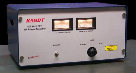 Schematics plans by K9GDT and all infos to build a 600 Watt HF Amplifier. The amplifier uses four Motorola MRF150 50 volt TMOS power FETs configured in push-pull/parallel and biased for class AB linear operation.
 -
 The Pfeiffer Maltese Quad Antenna System presents a unique approach to traditional quad antennas by utilizing a linear loading technique. This method effectively reduces the overall size of the antenna while maintaining its performance capabilities. Designed by Andrew Pfeiffer, the antenna's configuration resembles a Maltese cross, which not only enhances its structural integrity but also allows it to withstand challenging environmental conditions. This system is adaptable, offering various configurations from a 4-spreader Maltese Quad to a 16-spreader Maltese Quadruple-Cross, making it suitable for operators looking to optimize their setup without sacrificing efficiency. This antenna system is particularly versatile, covering multiple bands including 40, 20, 17, 12, and 10 meters. The design focuses on minimizing the physical footprint while ensuring effective signal transmission and reception. Amateur radio operators can benefit from the detailed plans available in the accompanying PDF, which outlines the construction process and specifications. Whether you're a seasoned DXer or a newcomer to the hobby, the Pfeiffer Maltese Quad Antenna System offers a practical solution for enhancing your station's capabilities.
 -
 A 9 dB gain 70cm collinear antenna construction is detailed, utilizing eight half-wavelength sections of _RG58/U_ coaxial cable. The design incorporates specific calculations for velocity factor (0.66 for RG58/U) to determine precise element lengths, such as 223mm for a half-wavelength at 444 MHz. A quarter-wave radiating element of #16 solid wire, 169mm long, is added to the top, and a 160mm aluminum tube acts as a quarter-wave counterpoise at the feed point. RF choke baluns, constructed from three _FT50-43_ toroids, are positioned a half-wavelength from the feed point to mitigate common mode current. Assembly involves soldering the coax sections in series, followed by SWR testing during construction and final mounting within a ¾-inch PVC pipe. The article suggests using four half-wave elements for a shorter antenna, noting a potential slight increase in SWR, which can be mitigated with quarter-wave ground radials. The design principles and formulas are scalable for other VHF/UHF bands like 6m, 2m, or 1¼m, providing a versatile homebrew solution for enhanced gain.
 -
 RF Concepts manufacturer of Alpha Linear Amplifiers, amateur radio RF power amplifiers, commercial power amplifiers, power meters and dummy loads.
 -
 Use 4CX10000D / 8171, RF output power of 11 KW in key-down carrier on all bands. Power was measured with a Bird 4712 wattmeter and a 25 KW slug
 -
 Over 25,000 amplifiers and sub-assemblies were produced by Angle Linear for the communications industry over a 40-year period. The company specialized in **high-linearity RF products**, focusing on preamplifiers, bandpass filters, and receiver multicouplers. Specific product lines included PHEMT and GaAs FET preamplifiers, offering both quadrature and single-ended configurations for various signal levels. The offerings encompassed coaxial and combline bandpass filters, along with integrated filter-preamplifier assemblies. The company also provided custom RF assemblies, addressing applications such as MRI preamplifiers, passive radar, and EME (moon bounce). Their product range covered VHF and UHF frequencies, including specific designs for 2m, 70cm, and 23cm bands, often featuring high IP3 performance. Technical documentation, such as filtering application notes and duplexer theory, was also associated with their product offerings.
 -
 This Vertical antenna design by David Reid for lower bands focuses on achieving effective DX communication by optimizing the antenna low-angle radiation for long-distance contacts. The design incorporates techniques like linear loading and capacity hats to reduce the antenna's height while maintaining performance, especially on 40m and 80m bands. Building a solid ground plane and using quality materials ensure efficiency and durability. Although vertical antennas can be complex to build, this project simplifies the process, making it accessible for ham operators seeking strong, reliable signals.
 -
 Based on Motorola MRF454, schematics and component list
 -
 A 144 MHz kilowatt amplifier project details the construction and performance of a high-power VHF linear using the GU74b tetrode. This Russian tube, equivalent to the Svetlana 4CX800, is noted for its conservative datasheet ratings, performing closer to 800-1000W anode dissipation in practical applications. The design prioritizes compactness and achieves 1.2 kW output with only 20W of drive power, demonstrating a 70% efficiency at 2.5 kV plate voltage. The amplifier has been successfully deployed in demanding _EME_ (Earth-Moon-Earth) operations since June 1994. Challenges encountered during development included achieving stability with a grid-1 input configuration. The author, _CT1DMK_, opted not to publish the full design due to its complexity, suggesting it might be difficult for less experienced builders to replicate successfully. However, he invites direct contact for those with specific interest in the design. Future plans include a "144MHz GS35b compact amplifier" project, promising another kilowatt-plus design. This resource offers insights into high-power VHF amplifier construction and the practical application of specific power tubes.
 -
 manufactures and distributes HF, VHF, UHF and SHF equipment covering 10MHz. - 47.0GHz. Our products include: Wireless LAN / WAN Bidirectional Linear Amplifiers, Low Noise Preamplifiers - LNA's, RF Linear Amplifiers, Relays, Transverter Systems, Frequency Translation Systems, Downconverters, Antennas, Parabolic Dishes, Coaxial Cable, Relays, Antenna Switches, Microwave Test equipment, PC controlled Receivers, Microwave Linear Amplifiers including models for Telemetry, Wireless, and CDMA applications.
 -
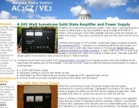
 Constructing a high-power solid-state amplifier for HF operations presents unique challenges, particularly when aiming for significant output like 600 watts. This project details an amplifier design employing **Motorola MRF150** FETs, a common choice for their robust performance in RF power applications. The design emphasizes achieving substantial power output, a critical factor for effective DXing and contesting, where every decibel can make a difference in signal propagation and readability. While specific circuit diagrams or construction details are not directly presented on the current page, the mention of MRF150 FETs points towards a design that would typically involve push-pull configurations, impedance matching networks, and robust power supply considerations to handle the high current demands. Such amplifiers are often built with an eye towards linearity and efficiency across the HF bands. Amateurs pursuing similar high-power solid-state projects often share insights on thermal management, intermodulation distortion, and component sourcing, all vital for a stable and reliable amplifier capable of delivering 600 watts into a proper antenna system.
 -
 WorldRadio Article on Petlowany antennas base on this principle: if a length of wire is wound into a spiral-shaped coil and excited by a radio frequency current connected to the innermost portion of the coil, it will then, and only then, exhibit RF characteristics that closely approximate those of a resonant linear wire of the same length
 -
 Constructing a linear focus parabolic antenna for WiFi operation involves precise metalwork, as detailed in this project. The author, AB9IL, shares a build that can be completed in a few hours, emphasizing the hands-on process of shaping and assembling metal components. This design aims to provide enhanced signal range for 2.4 GHz wireless networks, a common challenge in many ham shacks and home setups. The project outlines the practical steps required, from initial measurements to the final assembly, including cutting, bending, and bolting various metal parts. While specific gain figures are not provided, the parabolic design inherently offers significant _directional gain_ compared to omnidirectional antennas, making it suitable for point-to-point links or extending network coverage over distances. The construction process focuses on readily available materials and basic shop tools, aligning with the DIY spirit prevalent in amateur radio. This antenna project is presented as a straightforward build, requiring attention to detail in fabrication to achieve optimal performance.
 -
 The Discovery series of amplifiers are designed and built in the UK by Linear Amp UK Ltd, one of the world's leading amplifier manufacturers, specializing in high power RF tube amplifiers. The amplifiers use large GS31 or GS35 ceramic triode tubes. Band coverage 6m, 2m and 70 cms
 -
 Interfacing tips for ICOM IC-706MKII transceiver with a Collins 30L-1 linear amplifier
 -
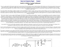 Restoring vintage amateur radio gear often presents challenges with accurate dial calibration due to the non-linear characteristics of analog tuning capacitors. This resource details the construction of a 100 kHz crystal calibrator, a crucial tool for precisely setting the frequency of older rigs lacking digital readouts. The design cleverly circumvents the scarcity and cost of 100 kHz crystals by utilizing a readily available 8 MHz microprocessor crystal, such as a _HC49U_ type, in conjunction with common _CMOS ICs_ like the 74HCT00 quad NAND gate and 74HCT393 dual 4-bit binary ripple counter. The circuit employs a two-stage frequency division process: the 8 MHz crystal oscillator output is first divided by 16 to yield 500 kHz, then further divided by 5 to achieve the desired 100 kHz output. A 5.1-volt Zener diode, _1N4733A_, regulates the power supply for the HCT series logic. The article also provides a modification to produce a 50 kHz calibrator by altering the counter reset logic. Installation involves feeding the output to the receiver front end, ensuring it's post-TR relay to prevent RF damage, and incorporating an ON/OFF switch for the 12V supply line.
 -
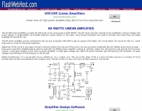 The 60 Watt linear amplifier is simple all solid state circuit using power mosfet IRF840.
 -
 A solid state linear based on EB104 Motorola Engineering Bulletin by Helge Granberg. It uses 4 MRF150 FETs in push-pull parallel to acheive 600 Watts from about 6 Watts drive
 -
 Presents a construction project for a linear-loaded 40-meter rotatable dipole, detailing the design evolution from mid-element coils to 300-ohm twinlead loading. It covers material selection, including repurposed fishing poles and EMT conduit, and outlines the assembly process for the antenna elements and mounting plate. The resource provides specific measurements for element lengths and linear loading sections, along with SWR plots demonstrating the antenna's resonance at 7.035 MHz with a 1.1:1 SWR, and bandwidth up to 7.120 MHz below 2:1 SWR. The article documents the antenna's performance during various RTTY and CW contests, including the SARTG RTTY and SCC RTTY contests in August 2006, and the ARRL DX CW and CQWW WPX RTTY contests in February 2007. It reports successful operation at 500-1000W, noting improved performance after replacing a faulty coax cable. Specific DX contacts from British Columbia, including stations in Europe and South Africa, are listed, illustrating the antenna's capability despite its shortened length and relatively low height of 55 feet. The content highlights practical considerations such as weatherproofing the connections and supporting the fiberglass elements to prevent sagging. It also includes a brief comparison to an inverted-V at similar height and a ground-mounted vertical, noting the rotatable dipole's quieter reception. The author shares insights into the iterative design process and tuning adjustments made to achieve optimal resonance.
 -
 Whether we are tuning up homebrew equipment, checking antenna VSWR, adjusting a linear amplifier, or just monitoring output power during a contest, almost all aspects of ham operation can use a power meter. Paul Wade W1GHZ
 -
 The two linear amplifiers are ment for use with QRP SSB/CW/FM/AM transmitters on the amateur bands 15 and 17 meters can be powered from a 12 volt DC supply by ON6MU
 -
 The Collins TRC-75 autotune linear amplifier, owned by JF2SVU, is presented with a focus on its internal modifications. This QRO amplifier utilizes three 4CX250 tubes in parallel for its final stage, delivering 1 KW output power. Notably, the amplifier achieves full power with only 100 mW of RF input, a characteristic often associated with Collins designs. The original 400 Hz power supply has been converted for easier shack integration, and the entire RF and power supply sections have been rehoused into a compact, clean enclosure. The control unit, positioned above the amplifier, features three meters for individual vacuum tube IP monitoring and a multi-meter on the right. A dedicated 7 MHz receiver, recently completed, is also part of this integrated system. The autotune functionality means the main amplifier unit only requires connections for power, control, and coaxial cables, simplifying its operation. Key components like the 4CX250 tubes and NF capacitors are visible, along with the gearing mechanism for the final tank circuit. A timer and relay system manages high-voltage delay and cooling fan off-delay, although the cooling fan's airflow is noted as somewhat insufficient. A central volume control, which experienced a contact issue, is also highlighted.
 -
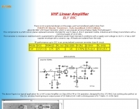 There is not a personal design on this page, just I've transfered useful notes from PHILIPS RF Bipolar Transistors - Data HandBook about BLY89C VHF Power transistor, which is very popular among Amateur Radio homebrewers
 -
 This program intended for electronic circuit analysis (mainly for Linux). ViPEC is a powerful tool for the analysis of high frequency, linear electrical networks.
 -
 Svetlana tubes also Russian capacitors,vacuum and coaxial relay, for RF Power Linear Amplifier builders. Amateur-Radio, Broadcast. Full Online Catalog.
 -
 This article loaded with nice pictures and schematics, describes a 160-10 meter linear amplifier that uses a pair of 3-500Z triode power tubes. It was designed and constructed by William Moneysmith, W4NFR. The amplifier features fast warm up and 1500-Watt RF output with 100-Watts of drive.
 -
 This is a prototype of the WA4DSY 56KB RF modem. It is intended for use on amateur packet radio networks. The modem generates RF in the 28 to 30 mhz range and requires and linear transverter to convert the signal to a UHF or microwave ham band
 -
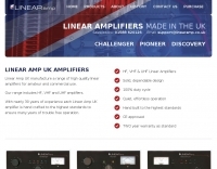 Linear Amp UK specializes in the design and production of high-quality linear amplifiers, offering models for HF, VHF, and UHF amateur and commercial applications. The company emphasizes nearly 30 years of experience in crafting each unit, ensuring robust performance and longevity. Their product line includes amplifiers engineered for a 100% duty cycle, promoting continuous and reliable operation across various modes. The amplifiers feature solid, dependable designs, ensuring quiet and effortless performance during transmission. Each unit is hand-built to stringent standards, reflecting a commitment to durability and operational stability. All products are CE approved, confirming compliance with European safety and environmental directives, and come with a standard two-year warranty, providing assurance to operators. Key specifications often include coverage for 1.8-30MHz (WARC bands), 50MHz, 70MHz, and 144MHz, utilizing tubes such as 811, 572, 811A, 572B, GS35, GS35B, 8877, 3CX1500, and _3CX1500A7_ in their designs.
 -
 TSC International produces soft magnetic sheet steel, custom-stamped and heat-treated to achieve optimal electrical characteristics for applications such as motors, generators, linear power supplies, and ballasts. The company's manufacturing process focuses on precise material engineering to meet specific performance requirements in various electrical systems. They also specialize in soft magnetic core materials essential for transformers, chokes, and inductors. These core materials are utilized in power supplies, lighting ballasts, signal conditioning circuits, inverters, and battery chargers, providing critical magnetic properties for efficient energy conversion and signal integrity. Located at 39105 Magnetics Blvd, Wadsworth, IL 60083-0399, TSC International provides contact via sales@tscinternational.com or phone at +1 (0) 847 249 4900, facilitating direct inquiries regarding their magnetic component offerings.
 -
 A 600W 1.8 MHz to 54 MHz power linear amplifier made using rugged MRF300 transistors featuring output power between 580W and 750W depending on band, power supply: 48V, 18A typical, 20A max
 -
 The collinear antenna, or Marconi-Franklin antenna, is an omnidirectional, high-gain antenna composed of in-phase half-wave dipoles aligned vertically. By using quarter-wave transmission line segments, it maximizes gain at a low horizon angle, outperforming a half-wave dipole. Adding segments increases gain but narrows bandwidth. A popular DIY version, the CoCo antenna, uses half-wave coaxial cable segments connected by non-radiating transmission lines. Built with stable velocity factor cables, a matching quarter-wave sleeve balun, and ferrite rings for attenuation, the antenna achieves performance comparable to commercial models.
 -
 RF amplifier products from NP Technologies, Inc. encompass a wide array of specialized designs, including highly linear Class A broadband amplifiers, crucial for maintaining signal integrity across various frequencies. Their portfolio also features cell band amplifiers, specifically engineered for cellular communication infrastructure, and pulse amplifiers, which are vital in applications requiring high-power, short-duration signal bursts. The company's manufacturing capabilities extend to AM and FM broadcast amplifiers, supporting radio transmission systems, and military VHF amplifiers, designed to meet rigorous defense specifications for robust and reliable communications. NP Technologies, Inc. emphasizes comprehensive development, design, manufacturing, and testing processes for all its RF amplifier offerings. This integrated approach ensures that each product, from initial concept to final deployment, adheres to stringent performance and reliability standards. The company's expertise in these areas allows for the creation of custom solutions tailored to specific client requirements, addressing complex RF challenges in diverse operational environments. Their product range demonstrates a commitment to serving multiple sectors, including commercial broadcasting, telecommunications, and defense. The focus on specialized amplifier types underscores their technical depth in RF engineering.
 -
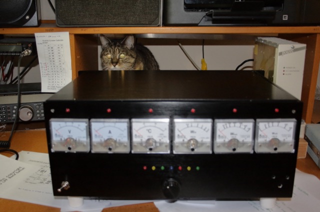
 Demonstrates the construction of a high-power 6-meter (50 MHz) amplifier, specifically designed for demanding modes like EME, TEP, and multiskip Es. It details the use of a _GU-43B_ tetrode in a grounded-cathode configuration, emphasizing the need for stabilized grid voltage and input capacitance compensation. The resource provides a comprehensive schematic, power supply design, and practical considerations for component sourcing, particularly for high-voltage and high-current sections. The builder achieved an output power of **1250 watts** with an anode current of 0.65 amperes and 3200 volts anode voltage. The article also covers the physical construction within a modified P6-31 enclosure, outlining the internal layout for RF and power supply sections, and includes photos of the completed unit. It highlights critical safety precautions for working with high voltages and reactive currents up to **20 Amperes** in the P-network.
 -
 Sixty-meter repeaters typically use a 1 MHz frequency separation between input and output, while 2-meter repeaters commonly employ a **600 kHz** split and 70-centimeter repeaters use a **5 MHz** offset. This article details the fundamental technical principles of amateur voice repeaters, explaining how they extend VHF/UHF communication range by receiving on one frequency and simultaneously retransmitting on another. It covers essential components such as receivers, transmitters, filters, and antennas, often situated on elevated locations for optimal coverage. The resource delves into the critical challenge of _desensing_—where the repeater's strong transmit signal overpowers its own receiver—and the engineering solutions employed, including antenna separation and the use of high-Q cavity filters. It also explores various control and timing systems, from basic squelch activation to more sophisticated microcontroller-based boards that manage functions like voice identification, time-out timers, and fault protection. Different access methods are discussed, including open access, toneburst, CTCSS subtone, and DTMF, each offering distinct advantages for managing repeater usage and mitigating interference. Furthermore, the article examines repeater linking, both conventional RF methods and modern internet-based solutions, highlighting how linking expands coverage and promotes activity across multiple repeaters or bands. It introduces less common repeater types such as 'parrot' repeaters, which use a single frequency and digital voice recording, and linear translators, capable of relaying multiple signals and modes simultaneously across different bands, often found in amateur satellites.
 -
 Design, develop, test and manufacture a wide range of Amplifier products including highly linear class A Broad Band, Cell Band, Pulse, AM & FM broadcast and Military VHF
 -
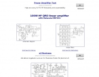
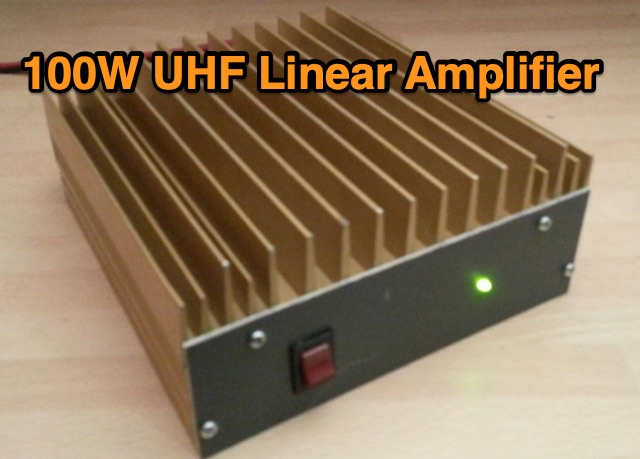 This page details my building of a 100 Watt Power Amplifier for the 432 MHz Band based on two Motorola MRF646 transistors taking inspiration by Carlo Gnaccarini VK3PY, formerly VK3BRZ
 -
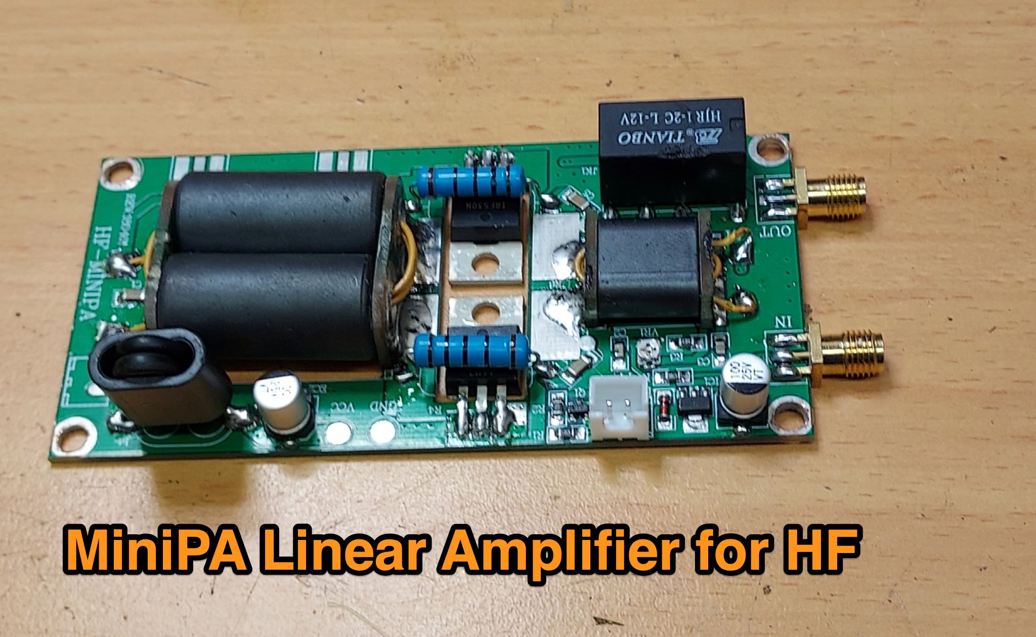 The MiniPA Linear Amplifier for HF page discusses the popularity of QRP for HF among ham radio operators, such as those using the Yaesu FT818 or low power SDR transceivers. It explores the use of cheap kits from eBay or Chinese suppliers to build a 70-100W SSB amplifier using IRF530 MOSFET transistors. The article provides a review of the MiniPA design, including its features, components, and assembly process. It also highlights the importance of using a heatsink and forced air cooling for optimal performance. This page is useful for hams looking to enhance their HF rig with a budget-friendly amplifier.
 -
 A rotatable 40-meter dipole antenna designed and constructed to fit within backyard constraints. The project utilized two fishing poles attached to a fiberglass center pole, resulting in an easy-to-build, lightweight, and cost-effective antenna. Essential materials included fishing rods, a center support pole, mast support, and basic tools. Linear loading was implemented to achieve the necessary length for optimal performance. The antenna, which proved effective during the contest, is ideal for field days and additional contest bands. Assembly and installation were straightforward, showcasing the antenna's practicality and efficiency.
 -
 Presents a detailed construction guide for a 9 dB, 70cm collinear antenna, utilizing readily available _RG58/U_ coaxial cable and PVC pipe for housing. The resource outlines the critical calculations for ½ wavelength sections at 444 MHz, incorporating the coaxial cable's velocity factor of 0.66, which yields a section length of 223 millimeters. It specifies the preparation and soldering of eight such half-wavelength sections, each cut to 231mm to allow for trimming, forming the core of the array. Further instructions detail the integration of a ¼ wave element (169mm #16 solid wire) at the top and a ¼ wave aluminum tube (160mm, 5/16 inch) at the bottom, crimped to the feed point's braid. The guide also addresses RF common mode current suppression by suggesting the use of _FT50-43_ toroids on the feedline. Final assembly steps cover mounting the antenna within ¾" PVC pipe using a wooden dowel, waterproofing connections, and initial SWR checks. The article also discusses scaling the design for different element counts and other VHF/UHF bands.
 -
 This is a power amplifier project for a RF 600W 1.8 MHz to 70 MHz linear amplifier including a Low Pass Filter. Projects includes schematics, pictures, PCD design, fans details, note on PA ferrite chokes and assembling instructions
 -
 The Shrunken Quad antenna is a unique design that offers full-sized performance on the 10m and 15m bands while incorporating linear loading via a trap for operation on the 20m band. This design allows for effective communication in the HF spectrum, making it suitable for both casual operators and serious DXers. The quad configuration provides excellent gain and directivity, which is beneficial for contesting and long-distance contacts. Constructing the Shrunken Quad involves careful attention to dimensions and materials to ensure optimal performance. The antenna's compact nature makes it an excellent choice for limited space situations, allowing operators to enjoy the benefits of a quad without the need for extensive real estate. This project is ideal for amateur radio enthusiasts looking to enhance their station's capabilities with a versatile and efficient antenna system.
 -
 The document provides a detailed modification guide for the Zetagi HP201 SWR Wattmeter, converting it for HF amateur band usage. It replaces the original circuit with a Tandem Coupler based on the Sontheimer and Frederick directional coupler patent, enhancing accuracy and sensitivity. Key components include Murata toroid cores, scaling resistors, and a new calibration process. Challenges and solutions during the modification process are discussed, ensuring linear results across 160-10m bands. This guide also includes calibration instructions and theoretical insights into the coupler's operation.
 -
 This article details the design and construction of a compact 20-meter QRP SSB transceiver by Pete Juliano, N6QW, measuring just 2 x 4 x 2 inches—small enough for a shirt pocket. Inspired by a 1963 QST design and refined from a prior version, it employs bilateral circuits, a 4.9152 MHz homebrew crystal filter, switched-crystal VXO for 60 kHz coverage (14.160-14.220 MHz), and standard components like ADE-1L mixers and IRF510 PA for 1W output. Key innovations include a double-sided PCB skeletal frame for shielding and isolation, Vectorboard sub-assemblies, and ultra-miniature relays. The bilateral receiver/transmitter shares stages, omitting AGC for simplicity, while a W3NQN LPF and optional 10W external amp enable DX contacts. Tune-up focuses on crystal matching and bias for linearity. Videos on YouTube demonstrate performance, confirming excellent stability and audio. Total cost nears $100, prioritizing portability over features like CW.
 -
 The Acom 1500 HF+6M Linear Amplifier is a high-quality and user-friendly amplifier that provides excellent performance and reliability. G6NHU, who previously owned an Acom 1000, upgraded to the Acom 1500 after nine years and has been using it for about eighteen months. Key features highlighted include the ability to connect three antennas internally, straightforward tuning process, robust construction that can handle high SWR, quiet operation, fast and quiet switching for efficient CW operation, and clean output signal even when driven hard. G6NHU highly recommends the Acom 1500 and states they would not hesitate to purchase another one in the future.
 -
 The Olivia digital mode, a **Multi-Frequency Shift Keying (MFSK)** radioteletype protocol, is specifically engineered for robust communication under difficult propagation conditions on shortwave radio bands from 3 MHz to 30 MHz. Developed by Pawel Jalocha in 2003, Olivia signals can be decoded even when the noise amplitude exceeds the digital signal by over ten times, making it highly effective for transmitting ASCII characters across noisy channels with significant fading and propagation phasing. Early on-the-air tests by Fred OH/DK4ZC and Les VK2DSG on the Europe-Australia 20-meter path demonstrated intercontinental contacts with as little as one-watt RF power under favorable conditions. Common Olivia modes are designated as X/Y, where X represents the number of tones and Y is the bandwidth in Hertz, with examples including 8/250, 16/500, and 32/1000. The resource clarifies that Olivia, unlike some other digital modes, produces a constant envelope, allowing RF power amplifiers to achieve greater conversion efficiencies and making it less prone to non-linearity. Operators are advised that **Automatic Level Control (ALC)** can be set higher than no meter movement for MFSK modulation, as long as it's not driven past its high limit, contrary to common misinformation about other digital modes. The Olivia community encourages voluntary channelization on suggested calling frequencies, such as 14.0725 MHz for 8/250, to facilitate initial contacts, especially for signals below the noise floor. The Olivia Digital DXers Club provides links to Groups.io, Facebook, and Discord for community engagement and offers details on QSO parties.