Search results
Query: modified
Links: 55 | Categories: 0
-
 Demonstrates the construction of a **multi-band HF mobile antenna** utilizing a modified CB whip antenna base. The resource details the process of stripping a commercial CB whip, winding a new helical coil with 0.7mm insulated copper wire, and identifying tapping points for various HF bands. It emphasizes the importance of a rugged, slim design for mobile operation, discussing mechanical length, power handling (up to 200 watts), and coil diameter considerations. The article includes a graphic illustrating the antenna's operational principle, where sections of the helical coil are shorted from bottom to top to maintain efficiency and high Q. The resource presents a practical approach to achieving **band switching** without an external tuner, by manually adjusting tapping points on the coil. It provides a table with reference lengths in centimeters from the feedpoint for 7 MHz (40m) through 28.7 MHz (10m), including WARC bands. The author details mounting techniques, suggesting a Diamond bracket for secure attachment to a vehicle trunk, and stresses the critical role of proper grounding for optimal performance. The design allows for operation on 75m and 80m bands by adding a 110mm steel whip.
 -
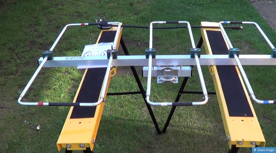
 A modified 20 meter double zepp wire Operating Bands: 40 thru 10 meters (with tuner), basic construction and performance information.
 -
 A 10-20 meters coverage delta loop antenna. After relocating, DL2HCB designed a multiband loop antenna to cover 10-20m with an open-wire feed for impedance matching and compact installation. Inspired by the mini-X-Q design, a modified 10m delta-loop was built, enhanced with a 1/4 wave shorted stub for 28 MHz using 450-ohm ladder line. The antenna delivers east-west broadside radiation and performs as a closed loop on other bands. Operational tests yielded strong European signals and successful DX contacts, including a 20m QRP QSO with FY/DJ0PJ.
 -
 This resource, last modified in August 2000, provides a personal amateur radio web presence for N3LS Larry, focusing on homebrew project announcements and a curated list of amateur radio links. It mentions plans for 10 to 15 new homebrew projects, indicating a focus on DIY electronics construction. The page also offers guidance for aspiring amateur radio operators, including tips for obtaining study guides and links to testing practice sites, suggesting an educational component for newcomers to the hobby. The content primarily serves as a personal hub, with a strong emphasis on sharing homebrew endeavors and supporting new licensees. While specific project details are not present, the intent to add numerous homebrew projects highlights a practical application of electronics knowledge. The inclusion of study resources aims to assist individuals in preparing for amateur radio license examinations, making it relevant for those seeking to enter the hobby.
 -
 A switchable antenna for 80/160 meters by IK1ZOY. A new version of a 1/4L 80 m. dipole modified for use in 160 m. band. using it's own coaxial cable feeder to wrap a coil.
 -
 Modified version of the Telerana antenna which was orginially featured in the July 1979 issue of QST. The array is suspended within a framework made of fiberglass poles emanating from a central hub with the ends tied together with light weight rope around the perimeter. 10-15-20-30-40 meter band coverage
 -
 The directory lists several files, including `_template1.html` and `_template2.html`, last modified in 2006 and 2004 respectively, indicating a historical web project. Key scripts like `hfcc_cfm.pl` and `index.cgi`, updated in 2011, suggest a **CGI-based application** for searching shortwave broadcast schedules. The presence of `_template1.tpl` and `_template2.tpl`, both modified in 2015, points to a templating system for dynamic content generation. The file `hfcc_create-fill_mys..>` (likely `hfcc_create-fill_mysql.pl`) implies interaction with a database, possibly MySQL, for storing and retrieving **HFCC (High Frequency Co-ordination Conference)** schedule data. The `lang.cgi` script, last updated in 2002, suggests early support for multilingual interfaces or language-specific content delivery. The `q.txt` file, a small 804-byte text file, could be a query log or a simple data file. The overall structure indicates a system designed to process and present shortwave broadcast information, likely by querying a database of scheduled transmissions on various HF frequencies. The file modification dates suggest the project was actively developed and maintained over a period spanning more than a decade, with core components last updated around 2011 and templates in 2015.
 -
 Demonstrates the construction and on-air performance of the _NB6Zep_ antenna, a modified 20-meter Extended Double Zepp design optimized for multi-band operation from 40 through 10 meters. The resource covers basic design principles, including dimensions of 66 feet horizontal and 5 feet vertical elements, and specifies open ladder line or TV twin lead for the transmission line. It details material selection for low-cost wire antenna construction, such as 18 AWG wire for the legs and ceramic or plastic insulators, along with practical tips for soldering connections and insulating against moisture. The author, NB6Z, shares insights from extensive _EZNEC_ modeling to optimize the antenna's total length for a 40-meter half-wave dipole footprint and feed line length for direct tuner connection. The article presents field results, including successful _PSK31_ contacts from Oregon to the East Coast on 40 and 30 meters with 50 watts, even at a low height of 6 feet. It provides detailed performance characteristics for each band, noting the _NB6Zep_'s highest gain (over 3 dB) and sharp, medium-angle lobes on 20 meters, which yielded strong DX reports to locations like Korea, Japan, and Argentina. For 17 and 15 meters, it describes a butterfly-like pattern with broad lobes, while 12 and 10 meters exhibit narrow, directional lobes in an "X" configuration. The author also shares personal experiences operating successfully for over a decade in an antenna-restricted environment using the NB6Zep and other stealth wire antennas.
 -
 The total length of this antenna is 41m, height is about 11m, and diameter of element is 2mm. JA7KPI modified this antenna originally used as Inverted-V type of 80m band Dipole. Works on 40 - 80 meters band with acceptable swr.
 -
 Some thoughts on a "hardware-store special" 2-meter quad, and a modified quad for 2 or 10 meters by K3MT
 -
-
 Based on a W4TWW project and modified by KN4LF
 -
 The homemade CW paddle key design, inspired by a QRP homepage, utilizes soldered PC board material for its construction. The builder, DL5NEJ, modified an existing design to achieve a smaller footprint, preferring a compact setup for portable operations. This paddle was specifically built to complement a Wilderness Radio SST20 QRP transceiver kit, demonstrating its suitability for low-power operations. The project details suggest a straightforward assembly process, with the primary components being readily available PC board scraps. The design emphasizes simplicity and functionality, aiming to provide a reliable keying experience comparable to commercial paddles like the Bencher. Performance evaluations indicated the simple paddle operates effectively, prompting further exploration into similarly minimalist QRP rig designs. Additional construction details for a similar paddle are available from PA0CMU.
 -
 Packet radio terminal program for win 3.1 and above, WinBox is a modified version of WinGT for cb radio usuage
 -
 An easy to build multiband trapped dipole that can work well on short low bands for skip contacts
 -
 6 element super duper moxon antenna for the 144 MHz, a modified HAARP Antenna projetc
 -
 Constructing a portable, high-gain antenna for _AO-40_ satellite operations presents unique challenges, particularly regarding mechanical stability and parabolic accuracy. This resource details the build of a 1.2-meter "brolly dish" antenna, utilizing a non-conducting fiberglass umbrella frame as its foundation. The project outlines a method for achieving a parabolic shape using stressed aluminum fly screen mesh, guided by practical geometry and a temporary dowel template. Key steps include selecting an appropriate umbrella with a suitable f/D ratio (ideally >0.25), removing the original fabric, and precisely cutting and attaching eight segments of fly screen to the struts to form the reflective surface. The construction process, which took approximately five hours for the author, _G6LVB_, resulted in a dish with an f/D of 0.27 (depth=270mm, diameter=1160mm, f=310mm). The article also describes a modification to a _TransSystem AIDC_ feed, incorporating a PCB reflector behind the dipole for easier mounting. Performance tests at a squint angle of 15 deg and a range of 50,000km yielded a signal-to-noise ratio of 33dB on the S2 beacon and 23dB for SSB signals, indicating strong reception. The author notes that the modified umbrella may not close fully without risking surface disfigurement.
 -
 This antenna was described by Bill, G4KIH in Sprat 52 and is actually a G5RV modified to fit into a small space.
 -
 This article presents a technical investigation into spurious emissions from the Yaesu FT-847 transceiver when operating on the 70MHz (4-meter) band. The author discovered significant problems with both factory "UK spec" and modified units. Spectrum analysis revealed that when transmitting at 70.2MHz, the radio produces numerous spurious signals, with the most prominent emission at 45.6MHz measuring only 3dB below the fundamental frequency. The study also documents poor power efficiency on 4m (10.3% at 30W output) compared to 6m operation (23.5% at 30W). Tests verified that jumper configurations had no effect on filter selection. The author warns that using these radios on 4m may violate license conditions due to excessive spurious emissions.
 -
 Over 1,000 stations in approximately 60 countries were worked using this modified twin-lead folded dipole, demonstrating its effectiveness with just 4 watts on 20 meters. This design, adapted from an ARRL Handbook concept, eliminates the shorting strap found in traditional folded dipoles, simplifying construction while maintaining performance. It utilizes readily available 300-ohm TV antenna feeder ribbon, making it a cost-effective solution for radio amateurs. The antenna's robust construction allows it to handle up to 100 watts without issues, even without a **balun**. The inclusion of a variable trimmer capacitor at the stub provides flexibility for tuning across different frequencies within a band, a practical feature for operators using transceivers like the Icom 735. Formulas are provided to calculate the precise dimensions for any desired operating frequency, enabling customization for various **HF bands**.
 -
 YY5PER video of a Icom IC-7000 modified for TV reception
 -
 Demonstrates how to construct an automatic band decoder, moving beyond manual selector switches for antenna and filter control. It addresses the challenge of varying band data outputs from different transceivers: Icom rigs provide voltage values, Yaesu rigs use Binary Coded Decimal (BCD), and Kenwood rigs lack direct band data output. The resource highlights a clever solution utilizing logging software like _CT (K1EA)_ and _DX4WIN_ to emulate Yaesu's BCD output via a PC's printer port, making the decoder compatible with any rig. The author details experiences building decoders based on designs by Bob _K6XX_ and Guy _ON4AOI_, noting K6XX's simple TTL chip design and ON4AOI's more comprehensive, opto-isolated unit capable of controlling ten outputs and bandpass filters like the _Dunestar_. It also references a _W9XT_ board design, which Steve Wilson, G3VMW, modified with BD140 transistors for source drivers, emphasizing safety. The author successfully cased an ON4AOI-based decoder in an old modem case, connecting it to an FT1000MP or a PC printer port to drive remote relays and a Dunestar Band Pass Filter.
 -
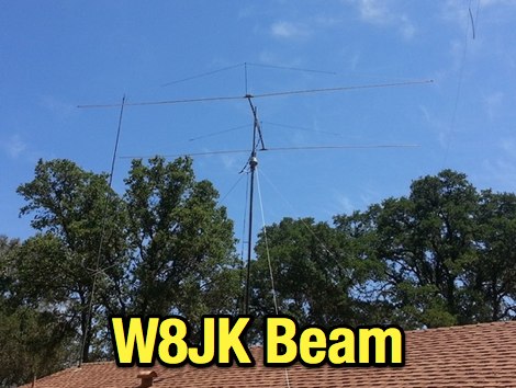 A compact 2 element W8JK beam antenna for 20M to 10M bands by AF6SA
 -
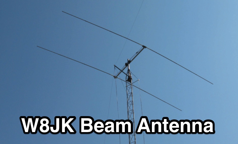 A Compact and efficient multiband beam antenna based on a Modified W8JK Array by K5LJ
 -
 Modification of the Bill Petlowany, K6NO antenna by N0LX
 -
 A well-known transverter modified for 10 MHz IF (for Softrock interface use) by DF9CY
 -
 A 200 kHz bandwidth digital transmission system for image transfer in the Amateur Service is under development, specifically targeting VHF allocations. John B. Stephensen, KD6OZH, leads this project under an FCC Special Temporary Authority (STA) valid until September 10, 2006, authorizing emissions up to 200 kHz bandwidth in the 50.3-50.8 MHz segment. Current regulations typically limit bandwidths to 20 kHz on VHF amateur bands, making this STA crucial for testing wideband digital modes. The modem, a modified **OFDM** (Orthogonal Frequency Division Multiplexed) unit, was initially tested on the 70-cm band. It splits a high-rate data stream into multiple low-rate subcarriers to mitigate multipath echoes. The system uses a DCP-1 card with a Xilinx XC3S400 FPGA and Oki Semiconductor ML67Q5003 microcontroller. The transmitter, located at 36d 46m 30s N, 119d 46m 22s W, generates 150 WPEP into an 8 dBi gain vertical antenna, while the mobile receiver uses a Ham-stick. Three data formats for 50, 100, and 200 kHz channels are being tested, with encoded data rates of 96, 192, and 384 kbps. Verilog code for the VHF OFDM modem is 95% simulated, with modifications from the UHF version including increased filter coefficient precision and a change from Ungerboeck **TCM** to BICM for improved performance over fading paths. Final tests will involve one-way over-the-air measurements of bit error rates and coverage area.
 -
 The antenna in this project is a modification of the techniques used to design a multiband fan type dipole with little or no tuning involved having a total space of 105 feet
 -
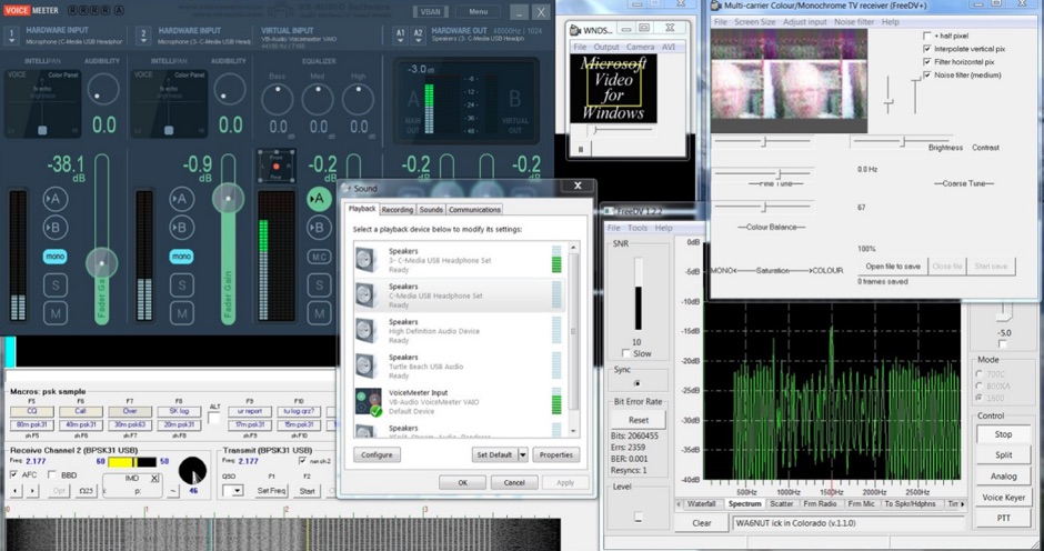 FreeDV plus Video adds simultaneous digital voice (FreeDV) to ZL2AFP's OFDM TV (see OFDM TV page listed under Software/SSTV and FreeDV page listed under Software/Digital Voice). An older version of OFDM TV is used, modified for compatibility with FreeDV. The video is 1 frame/sec, 36-lines, with full color. Total bandwidth is 3.5 kHz.
 -
 Demonstrates the construction of a high-power 6-meter (50 MHz) amplifier, specifically designed for demanding modes like EME, TEP, and multiskip Es. It details the use of a _GU-43B_ tetrode in a grounded-cathode configuration, emphasizing the need for stabilized grid voltage and input capacitance compensation. The resource provides a comprehensive schematic, power supply design, and practical considerations for component sourcing, particularly for high-voltage and high-current sections. The builder achieved an output power of **1250 watts** with an anode current of 0.65 amperes and 3200 volts anode voltage. The article also covers the physical construction within a modified P6-31 enclosure, outlining the internal layout for RF and power supply sections, and includes photos of the completed unit. It highlights critical safety precautions for working with high voltages and reactive currents up to **20 Amperes** in the P-network.
 -
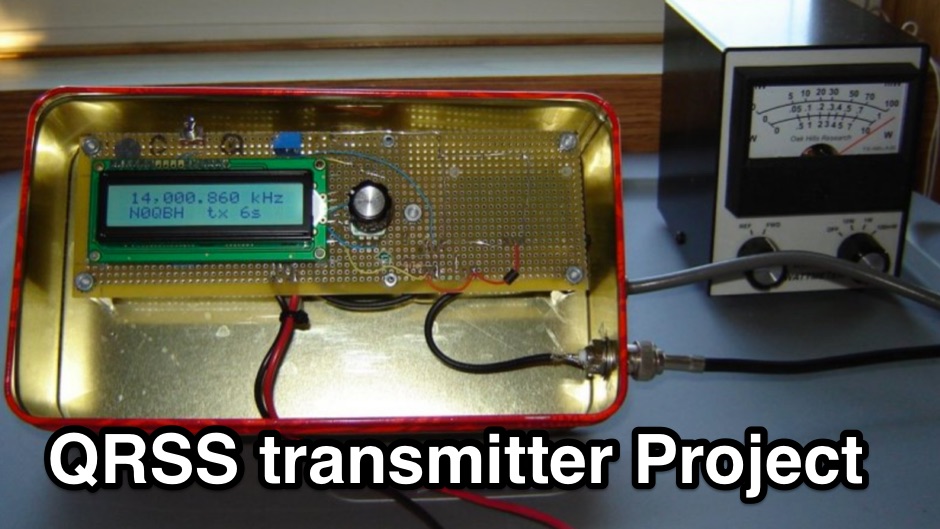 The N0QBH QRSS project page, a couple of projects using available kits for improved frequency and timing stability. A configurable DDS VFO 100mW transmitter with LCD display and a modified Hans Sommers 40m 100mW transmitter
 -
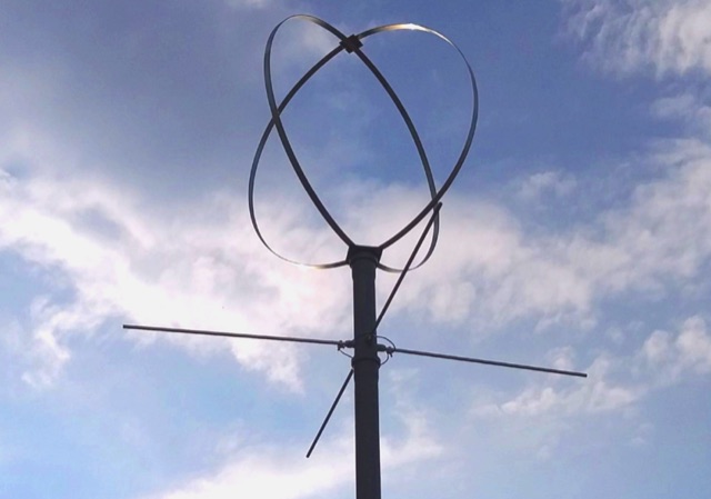 A modified Hairpin antenna for a wider bandwidth an mounted on a grounded metalic mast
 -
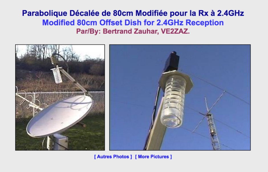 Modified 80cm Offset Dish for 2.4 GHz Satellite Reception. This 50-ohm impedance antenna allows, when connected to 2.4GHz preamplifier and downconverter, to receive Amateur satellites with 2.4GHz transponders such as AO-40.
 -
 The ZS1J/B beacon operates on 28.2025 MHz with 5 Watts output to a half-wave, end-fed vertical antenna, initially installed in 1977 as ZS5VHF near Durban. The 10-meter transmitter is a modified 23-channel CB radio, and the identification keyer uses a diode matrix unit with TTL ICs from the same era. After relocation to Plettenberg Bay in 1993, the beacon has been in continuous service, with additional QRP transmitters later installed for other bands. In 1994, a single-transistor, 80-meter, 0.5-watt QRP transmitter with a half-wave dipole was added on 3586 kHz, followed by a 160-meter, 0.5-watt unit on 1817 kHz. A 30-meter, 0.5-watt transmitter was installed in 1996, operating on 10.124 MHz. In 2002, a 40-meter QRRP beacon on 7029 kHz, with an output of 100 microwatts, achieved DX reports up to 1100 km from ZS6UT in Pretoria. Best DX reports for the 80m and 160m beacons came from 9J2BO.
 -
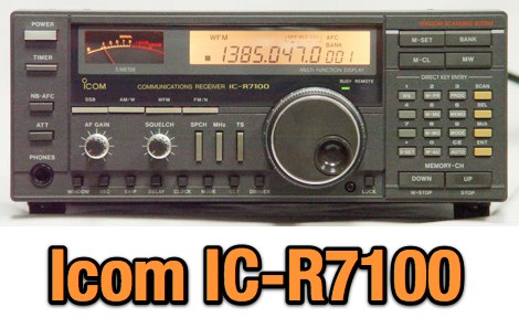 Notes on using a modified R7100 with discrimator tap
 -
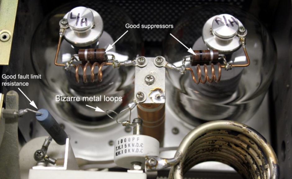 This amplifier had the full treatment, including nichrome hairpins, but they had to be removed because of parasitics or instability.
 -
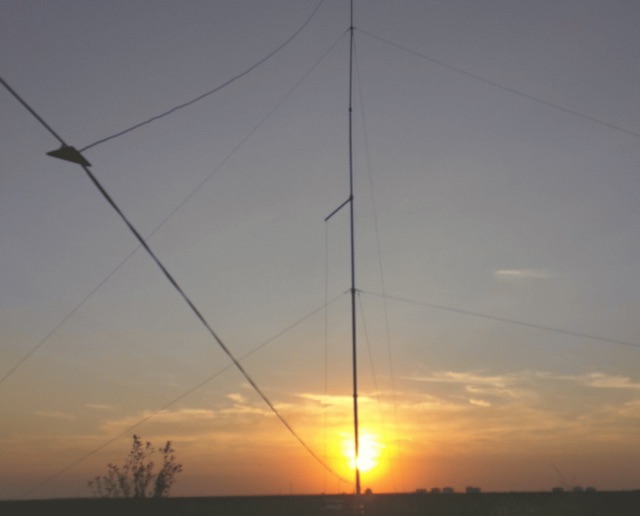 Results or performance test using an harpin antenna for the 7 MHz
 -
 _Amphenol RF_ manufactures RF connectors, RF adapters, RF attenuators, RF cable assemblies, and RF terminators. The company offers custom RF solutions, including modified connectors and integrated cable assemblies. Product examples include SMP to SMPM adapters, surface-mount SMB jack connectors, end-launch SMA bulkhead connectors, and non-magnetic SMPM connectors. The company's product portfolio also features single-crimp N-Type connectors, USCAR compliant Mini-FAKRA connectors, 2.4 mm to 2.4 mm adapters, and 2.92 mm plugs for 0.141-inch cable. _Amphenol RF_ produces MMCX and MCX cable assemblies on RG-316 and RG-174 cable, PFAS-free SMA connectors, and FAKRA rear mount bulkhead plugs for RG-58 and LMR-195 cable. Additional offerings include 2.92 mm to 2.92 mm adapters, BNC bulkhead jacks, SMA to MHF 4 LK cable assemblies, and 2.92 mm to SMA adapters. _Amphenol RF_ is headquartered in Danbury, Connecticut, and operates as part of _Amphenol Corporation_. The company maintains a global manufacturing and distribution network. DXZone Focus: RF connectors | Cable assemblies | Danbury, Connecticut | _Amphenol Corporation_
 -
 Home made 40 meter transceiver project. The receiver is a Progressive Receiver with a few modifications. The Transmitter is a modified MFJ Cub circuit. Includes schematic and circuit diagrams for Receive Input Filter, 3-Pole 500 Hz Cohn Filter and 7 MHz Double Tuned Bandpass Filter
 -
 WSJTX-Controller-v2, or Otto, functions as an assistant for the WSJT-X amateur radio program, specifically designed to enhance operational efficiency for weak signal digital modes. The software automates several key tasks, including call management, prioritizing DX stations based on user-defined criteria, and optimizing frequency selection within the WSJT-X interface. It requires a modified version of WSJT-X to function correctly, integrating directly with its core processes to provide augmented control. Otto supports various digital modes, facilitating auto-logging of contacts and generating specific alerts for desired stations or conditions. It is engineered to streamline the workflow for operators engaged in DXing and general weak signal communication, offering features like automatic CQ responses and intelligent band monitoring. The utility is not compatible with certain other amateur radio software and is explicitly noted as unsuitable for contest operations or the WSJT-X Hound mode, indicating its specialized focus on non-contest DX and casual operating. The project's GitHub repository provides the source code and documentation, allowing users to review its implementation and contribute to its development. The software's design emphasizes automation to reduce operator intervention during routine digital mode operations.
 -
 Otto enhances WSJT-X, the popular weak-signal digital modes program for amateur radio. It automates tasks like managing QSOs, prioritizing DX stations, replying to specific calls, and optimizing band usage. Otto works with a modified WSJT-X version (v2.7.0) to add advanced features such as directed CQs, automatic logging, and multi-stream replies. Its intuitive modes streamline operations, while safety measures ensure controlled transmissions. Ideal for DX enthusiasts, Otto improves efficiency and focus, making weak-signal operations more engaging and productive.
 -
 This blog chronicles the development of an 80-meter vertical antenna for amateur radio operation. The author constructs a top-loaded vertical using fiberglass poles, achieving significant performance improvements over their previous end-fed wire antenna. Comparative testing using the Reverse Beacon Network and on-air contacts demonstrates 8-10 dB gain on the east coast. The project evolved to include 40-meter capability through a modified design featuring a four-wire vertical cage, loading coil, and strategic guying system. Despite challenges with signal wobble during windy conditions, the vertical consistently outperforms the end-fed wire, particularly for reaching distant stations during nighttime propagation.
 -
 Initially planned as an article on the R-407 station mast, this project evolved into creating a custom mast kit. Utilizing original materials, the design was modified for cost-effectiveness and practicality in home assembly. The new mast extends to 10 meters, featuring secure connections, a leather-lined base to prevent metal-on-metal friction, and sturdy military-grade anchors. Modifications include lengthened connecting tubes, improved anti-rotation features, and a convenient base design for solo assembly. Ideal for amateur radio operators, this mast provides stability, ease of construction, and versatility, proving more economical than professional products without compromising on performance or reliability. Article in Czeck.
 -
 This project delves into the development of a compact WSPR beacon, building on earlier experiences with weak-signal modes. Inspired by QRP Labs kits and modified open source designs, it integrates a Si5351 frequency generator, GPS module, and class E PA for efficient operation. Extensive optimizations—addressing drift, heat management, and power stability culminated in a portable, serviceable device. The beacon offers insights into propagation while minimizing reliance on main station equipment. Lessons learned highlight the importance of careful component selection and iterative design improvements for robust amateur radio experimentation.
 -
 The Butternut HF2V, originally a two-band vertical antenna for 80m and 40m, was enhanced by the user to include 30m and 20m bands for better digimode DX work during the solar minimum. The additions used components adapted from the HF6V and innovative methods for the 20m addition, either through a parallel vertical element or a lower-mounted independent element, minimizing band interaction. This modified four-band antenna now supports high power across popular HF bands using a single feedpoint.
 -
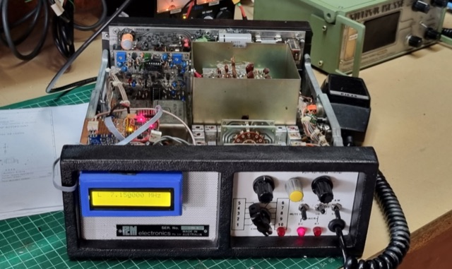 This article describes an upgrade to the Kestrel transceiver, replacing its LCD display with a 0.91-inch OLED screen for improved sound quality. VFO boards from Denys VK3ZYZ were integrated, particularly a Nano VFO board. The author shares details about the setup and the resulting enhancements, along with images of the modified components. The transceiver is now optimized for various frequencies and operates at a power output of approximately 120 W pep. More information about the boards can be found on the provided website.
 -
 The article discusses the use of SDR# (SDR SHARP) software for SDR receivers, highlighting its Band Plan feature that visually represents RF spectrum allocations. The author modified SDR# to display detailed IARU HF band plans, creating three XML files for different IARU regions. These files include various operational modes and specific frequency allocations. Despite potential errors, the modifications aim to enhance the usability of SDR# for ham radio operators. The article includes references and download links for the XML files and IARU band plans.
 -
 AutoEZ, Automated use of EZNEC, is an Excel workbook that works alongside EZNEC antenna modeling software version 5.0 or later. With AutoEZ, you can control different aspects of your model using variables and run multiple EZNEC test cases automatically. Formulas in Excel allow you to modify any part of the model. AutoEZ's interface resembles EZNEC's. Enabling macros in Excel might be necessary before using AutoEZ. The program opens various model file formats including EZNEC (.ez), NEC (.nec or .inp), AO and NEC/Wires (.ant), and MMANA-GAL (.maa). You can set the frequency and/or variable values for the test cases to be run through EZNEC. AutoEZ allows you to create animations showcasing how the pattern changes as the model configuration is modified. You can download a fully working, but limited demo copy from this site.
 -
 A 13-foot total radiating element length is achieved by combining a Buddipole Long Telescopic Whip with 4 feet of modified tripod tubes, forming a low-profile, multiband antenna for **POTA** operations. The resource details the transformation of an Amazon Basics Aluminum Light Photography Tripod Stand, focusing on electrically isolating the top two radiating sections from the bottom support. John, VA3KOT, outlines component sourcing, including the 9-foot 4-inch fully extended whip, and emphasizes using adhesive copper tape for reliable electrical contact and conductive grease to prevent oxidation at tube connections. The construction process, while not requiring specialized tools, highlights careful assembly to ensure proper electrical conductivity and mechanical stability. The author's experience with this setup suggests its effectiveness for portable activations, offering a discreet profile compared to larger antenna systems. The design prioritizes ease of deployment and transport, making it a practical solution for operators seeking a compact yet versatile antenna for field use.
 -
 This article explains the trick of how to shorten and lengthen pairs of radials to make a 2-band ground plane antenna. Included is a "Table of Multi-Band Possibilities" covering the range of 6 to 40 meters.