Search results
Query: noise source
Links: 52 | Categories: 1
Categories
-
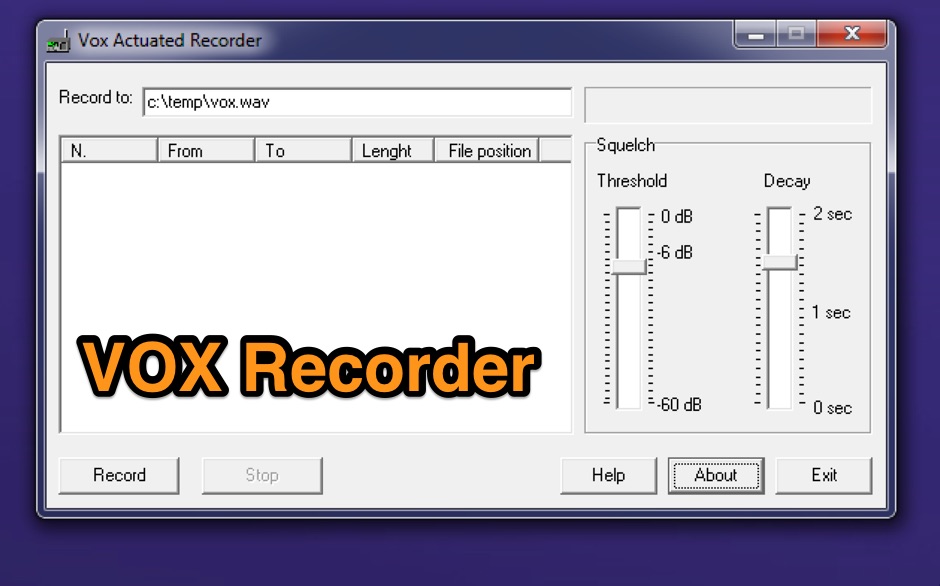 Vox Recorder is a specialized Windows utility designed for amateur radio operators, and radio listeners particularly those who use radio scanners. This software allows users to record audio from various sources, but it only activates when an audio signal is detected. This feature is particularly useful for avoiding the capture of silence or background noise, which can be common in radio scanning. By focusing on the audio signals, users can create cleaner recordings that are more relevant to their interests. The utility is user-friendly and tailored for hobbyists who want to document their radio listening experiences without the hassle of editing out silence later. Vox Recorder is an excellent tool for anyone involved in amateur radio, as it streamlines the recording process and enhances the overall experience of monitoring radio frequencies. Whether for personal use or for sharing with fellow enthusiasts, Vox Recorder helps ensure that every important transmission is captured effectively.
 -
 Over 40 years of experience inform the reviews and commentary presented on Dave's Radio Receiver Page, covering a wide array of radio receivers and transceivers. The resource details specific models such as the **ICOM IC-R8600** SDR Communications Receiver, which is lauded as Icom's best wide-band receiver, even surpassing the IC-R9500 in performance. Other notable reviews include the ICOM IC-7300 HF Transceiver, highlighting its direct sampling SDR technology and spectrum scope capabilities, alongside numerous models from Japan Radio Co. (JRC), Kenwood, Yaesu, and various portable shortwave receivers. The content provides practical insights into the performance and characteristics of each radio, often drawing comparisons between models. For instance, the early issues with the AOR AR7030 receiver's Bourns mechanical encoders are thoroughly documented, including AOR's eventual switch to higher-quality Alps encoders. The page also features reviews of antennas like the MFJ-1026 Noise Canceling Signal Enhancer and various power supplies, offering a holistic view of radio monitoring setups. The author's "2 ear / 2 eye method" emphasizes real-world listening experiences over laboratory measurements, providing a unique perspective on equipment utility.
 -
 RSCW demonstrates a Linux/Unix command-line utility engineered for **Morse code** decoding via a computer's sound card. It specifically targets the extraction of weak CW signals from noise, operating on 8-bit, 8000 samples/second audio input, typically from `/dev/dsp`. The program outputs decoded characters to `stdout`, supporting user-specified speeds in words per minute (WPM) and carrier frequencies. While effective for machine-sent signals, it exhibits a 2-second decoding lag and requires manual speed input, making it less suitable for general-purpose, real-time contest operation. The resource details the program's components, including `rscw` (the main decoder), `rscwx` (an X11 graphical auxiliary for spectrum and internal signal visualization), `rs12tlmdec` (a specialized decoder for RS-12 amateur radio satellite telemetry), and `noisycw` (a utility for generating noisy Morse signals for testing). Installation instructions involve downloading a `.tgz` file, compiling with `Make`, and requiring the FFTW library (and GTK 2.0 for `rscwx`). Performance is illustrated with a .wav file example of a 12 WPM, 800 Hz CW signal at 12 dB Eb/N0, showcasing RSCW's near-error-free decoding of a test message. The site provides command-line examples utilizing `sox` for audio conversion and `noisycw` for signal generation, inviting comparisons with other decoding software and human operators, particularly for weak signal conditions.
 -

-
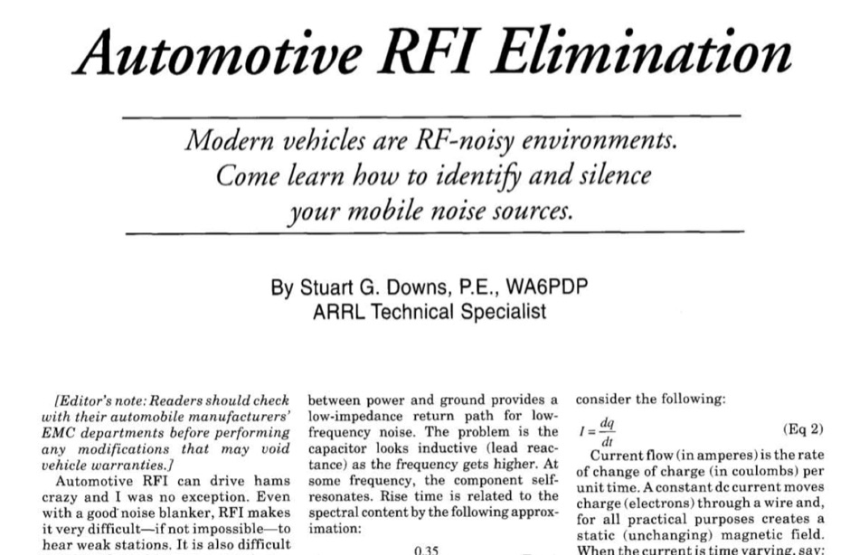 ARRL pdf file on how remove car noise from your radio. Modern vehicles are RF noisy environments. Come learn how to identify and silence yor mobile noise sources, by WA6PDP
 -
 The W1TAG LF Receiving Loop is a specialized antenna project for LF reception, designed to mitigate local noise and enhance weak signal pickup on the lower frequencies. This square loop, measuring 6 feet per side, utilizes 14 turns of #12 THHN wire wound on a PVC frame, offering a robust mechanical structure. The design incorporates a series-tuned circuit with a coupling transformer, allowing for tuning from over 400 kHz down to _45 kHz_ using a switched capacitor bank. Construction details include the use of 1.5-inch PVC pipe for the frame, with specific measurements for spreaders and drilled holes for wire threading. The two 7-turn sections of wire are connected at the center, providing an option for a center tap. The loop rotates on a 1-inch steel pipe, enabling directional nulling of noise sources. The tuning unit, housed in a box clamped to the PVC, employs a 1:2 step-up transformer wound on an _FT-82-77 core_ and uses relays to switch capacitance values from 50 pF to 6400 pF, providing precise frequency adjustment. The current setup connects to the shack via 100 feet of RG-58, feeding into a W1VD-designed preamp, with plans for a balanced, shielded twisted pair cable upgrade.
 -
 Engaging in **QRP** operations, where amateur radio transceivers transmit at five watts or less, presents a unique challenge and satisfaction for many radio amateurs. This mode emphasizes efficient antenna systems, keen operating skills, and often, the art of **homebrewing** equipment to maximize performance under power constraints. Operators frequently utilize CW (Morse code) for its superior signal-to-noise ratio, enabling reliable contacts over long distances with minimal power. The VK QRP Club, formally known as the CW Operators' QRP Club Inc., serves as a focal point for Australian amateurs passionate about these low-power pursuits. The club fosters a community where members can share insights on antenna design, circuit construction, and operating techniques specific to QRP. It provides resources such as information on club nets and frequencies, Morse practice materials, and a platform for exchanging ideas among enthusiasts. Membership offers access to a network of like-minded individuals, promoting the continued development and enjoyment of QRP within the amateur radio hobby. The club's activities encourage experimentation and skill refinement, vital aspects of successful low-power communication.
 -
 Demonstrates the construction of two distinct wideband RF preamplifiers, detailing their component requirements and performance characteristics. The first design leverages monolithic microwave integrated circuits (MMICs) such as the MAR-6, MAR-8, or PGA103, offering a broad frequency response from DC to 2 GHz with a gain of 22.5 dB at 100 MHz and a noise figure typically below 3 dB. This MMIC-based amplifier incorporates protection against power supply transients and features a 50 Ohm input/output impedance, operating from an 8-20 volt supply with low current drain. The second preamplifier design utilizes a BSX-20 transistor, providing amplification across the 14 MHz to 550 MHz range. This simpler, more economical build achieves an average gain of 12 dB at 145 MHz and a noise figure of approximately 1.1 dB. It operates from a 7-15 volt battery supply with a current draw of 6 mA. Both projects emphasize critical construction techniques, such as maintaining short RF connections, ensuring 50 Ohm impedance paths, and mounting the circuit within a shielded enclosure to optimize performance and minimize noise. The resource also discusses phantom power options for antenna-mounted preamplifiers and precautions for use with transceivers, including output protection diodes and static bleeders.
 -
 Constructing a portable, high-gain antenna for _AO-40_ satellite operations presents unique challenges, particularly regarding mechanical stability and parabolic accuracy. This resource details the build of a 1.2-meter "brolly dish" antenna, utilizing a non-conducting fiberglass umbrella frame as its foundation. The project outlines a method for achieving a parabolic shape using stressed aluminum fly screen mesh, guided by practical geometry and a temporary dowel template. Key steps include selecting an appropriate umbrella with a suitable f/D ratio (ideally >0.25), removing the original fabric, and precisely cutting and attaching eight segments of fly screen to the struts to form the reflective surface. The construction process, which took approximately five hours for the author, _G6LVB_, resulted in a dish with an f/D of 0.27 (depth=270mm, diameter=1160mm, f=310mm). The article also describes a modification to a _TransSystem AIDC_ feed, incorporating a PCB reflector behind the dipole for easier mounting. Performance tests at a squint angle of 15 deg and a range of 50,000km yielded a signal-to-noise ratio of 33dB on the S2 beacon and 23dB for SSB signals, indicating strong reception. The author notes that the modified umbrella may not close fully without risking surface disfigurement.
 -
 This resource, "Transistor Audio Preamplifier Circuits," offers comprehensive design guidelines for constructing **bipolar transistor** audio preamplifiers. It delves into critical aspects such as quiescent current setting, voltage gain calculation, and the impact of various component choices on circuit performance. The content provides several _schematic diagrams_ illustrating different preamplifier configurations, including single-stage common emitter and two-stage designs, alongside explanations of their operational characteristics and practical implementation considerations. The analysis extends to frequency response, noise performance, and distortion, providing insights into optimizing these parameters for specific audio applications. The resource presents calculated gain figures for various stages, demonstrating how to achieve desired amplification levels. It also discusses the importance of proper power supply decoupling and input/output impedance matching, crucial for integrating these preamplifiers into larger audio systems or ham radio transceivers. The practical application of these designs is evident in their suitability for microphone preamplifiers or general-purpose audio amplification.
 -
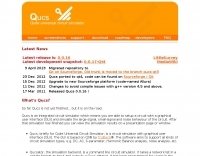 Qucs, briefly for Quite Universal Circuit Simulator, is an integrated circuit simulator which means you are able to setup a circuit with a graphical user interface (GUI) and simulate the large-signal, small-signal and noise behaviour of the circuit. After that simulation has finished you can view the simulation results on a presentation page or window. Run on Linux.
 -
 Optimizing a G5RV or ZS6BKW multiband wire antenna for HF operation often involves addressing common SWR issues and understanding feedline characteristics. This resource chronicles the construction and performance evaluation of a G5RV, initially built for 80m, 40m, 15m, and 10m bands, by a newly licensed Foundation operator. The author details the selection of materials, including 3.5 mm stainless steel wire for the doublet arms and enameled copper wire for the open-wire feeder, and the initial decision to omit a balun based on common online information. The narrative highlights the initial disappointing performance, characterized by high receive noise and poor signal reports on 80 meters, despite the transceiver's internal ATU achieving a 1:1 match. This led to experimentation with a coax current balun and further research into G5RV myths, such as SWR claims and the necessity of a balun. The author then describes modifying the antenna to the ZS6BKW configuration, which involves specific changes to the doublet and feedline lengths, and integrating a 1:1 current balun wound on a ferrite toroid. The modifications resulted in improved reception and transmit performance across the bands.
 -
 This resource details the four primary functions of a ground system: lightning energy dispersion, equipment safety, RF return path provision for end-fed antennas, and management of induced RF currents. It clarifies that a ground system's effectiveness varies depending on its specific function, noting that a good lightning ground might not be an effective RF ground. The content emphasizes that proper antenna system design, including baluns and appropriate feedline lengths, often negates the need for an RF station ground to mitigate common mode currents or RFI in the shack. The article quantifies lightning energy, stating its peak is in the dozens or hundreds of kilohertz, with damaging energy extending to hundreds of megahertz, and currents reaching thousands of amperes. It recommends solid, wide, smooth copper surfaces for ground leads to achieve low impedance across a wide frequency range. The author, W8JI, shares practical insights from his station, which includes two 300-ft towers and four 130-ft wire verticals, detailing his use of common point grounds and _DX Engineering RR-8 HD_ antenna switches for lightning protection without coaxial surge protectors. Specific examples of antenna systems prone to common mode current problems are listed, such as random wire antennas without proper feedline lengths and off-center fed dipoles. The text also explains how a ground screen or radial system can reduce local noise sensitivity for vertically polarized antennas by covering the lossy earth.
 -
 The Receiver Test Data resource is a detailed review database focusing on the performance metrics of various radio receivers. The methodology involves rigorous lab measurements, often adhering to standards such as the ARRL RMDR (Reciprocal Mixing Dynamic Range) and BDR (Blocking Dynamic Range). Specific test equipment and protocols are utilized to assess parameters like noise floor (dBm), AGC threshold (uV), and LO noise (dBc/Hz). For example, the _Icom IC-7300_ is evaluated with a noise floor of **-133 dBm** and an LO noise of **-141 dBc/Hz**, providing insights into its performance under different operational conditions. The resource includes a wide range of models, from the _Elecraft K3S_ to the _Yaesu FTdx-101D_, each tested for dynamic range, sensitivity, and selectivity. The data is sorted by key metrics such as third-order dynamic range and phase noise limitations, with RMDR values calculated by subtracting 27 dB from LO noise figures. This structured approach allows users to compare different receivers' capabilities, focusing on technical specifications and performance outcomes in various scenarios. DXZone Focus: Review Database | Lab Measurements | -133 dBm | ARRL RMDR
 -
 This web article by VK3BLG details the construction of an experimental 70cm (432 MHz) circularly polarized patch antenna, intended for satellite communication. The resource provides dimensions, feed point specifications, and impedance matching considerations for a single patch element, with discussion extending to array configurations for circular polarization. Construction involves a copper patch element on a dielectric substrate, fed via a coaxial cable. The design is based on information derived from AO-40 satellite antenna specifications, focusing on achieving circular polarization for satellite reception. The article includes specific dimensions for the patch and feed points, along with impedance values. Validation is implied through on-air satellite reception reports, with initial signal reports of **1 S-point above noise** for AO-40 beacons using a grid reflector, improving to **3-4 S-points above noise** with a 2-turn helical feed. The author references a _NanoVNA_ for impedance measurements and discusses the relationship between slot and dipole antennas in the context of patch design. DXZone Focus: Web Article | 70cm Patch Antenna | On-Air Satellite Reception | Circular Polarization
 -
 This resource, originally intended to detail the technical specifications of the **Clover** digital communications mode, currently presents a "Page not found" error. The _Clover_ mode was designed for conveying 8-bit digital data over narrow-band high-frequency radio channels, offering robust performance under challenging propagation conditions. Its design focused on efficient data transfer and error correction, making it suitable for amateur radio operators seeking reliable digital links. The absence of the page prevents analysis of specific technical parameters, such as modulation schemes, data rates, or error correction codes that would have been presented. Historically, Clover offered significant advantages in throughput and reliability compared to earlier digital modes over HF, often achieving higher effective data rates than modes like PACTOR or AMTOR under similar signal-to-noise ratios. Without the content, a direct comparison of its performance metrics or practical application scenarios is not possible.
 -
 Mitigating RF noise in a mobile operating environment, particularly within a _Jeep TJ_ vehicle, presents unique challenges due to the vehicle's electrical system and chassis characteristics. This resource details practical methods for identifying and suppressing various forms of radio frequency interference (RFI) that can degrade receiver performance for both CB and amateur radio transceivers. It covers common noise sources such as ignition systems, alternators, fuel pumps, and computer modules, explaining how these components generate broadband or specific frequency noise that impacts radio communications. The guide offers actionable solutions, including proper grounding techniques, the strategic use of ferrite beads and toroids on power and data lines, and the installation of bypass capacitors. It discusses the effectiveness of different filtering strategies for DC power lines and antenna feedlines, illustrating how a clean power supply and shielded cabling can significantly reduce conducted and radiated noise. The information presented helps operators achieve a lower noise floor, improving signal-to-noise ratio and enabling clearer reception of weak signals, which is crucial for effective mobile DXing or local ragchewing.
 -
 Computers, TV's, and Switching Systems can cause noises to your receiver
 -
 Technical resource and information on improving ft1000 receiver performance
 -
 For over 20 years, bhi Ltd has specialized in digital signal processing (DSP) technology to mitigate noise and interference across various radio channels. Their product line, including the _ParaPro EQ20 Audio DSP_ units, focuses on enhancing receive audio quality, even for operators without significant noise issues, by offering precise parametric equalization to suit individual hearing preferences. The core offerings are noise-cancelling speakers and in-line modules, specifically engineered for amateur radio applications, but also adapted for commercial, PMR, and marine radio systems. The company provides audio demonstrations, such as a 20m SSB example and a 14MHz band filter comparison, allowing users to hear the effectiveness of their DSP units against common QRM sources like plasma TV interference or diesel engine noise. Located in Burgess Hill, West Sussex, UK, bhi Ltd emphasizes clear voice communications, aiming to remove unwanted noise and leave only intelligible speech.
 -
 Noise Meter software for the noise meter tool by G8KBB that measure noise using a PC sound card and calculate noise figures by means of a calibrated noise source.
 -
 Optimizing weak signal reception on the HF bands, particularly in the presence of strong local QRM, often necessitates specialized receiving antenna systems. This resource details the _HI-Z Antennas_ product line, focusing on phased vertical arrays designed for superior noise rejection and directivity. It covers components such as the 4-Square and 8-Element array controllers, which allow for rapid switching of receive patterns, and dedicated low-noise preamplifiers to improve system sensitivity. The site also presents various bandpass filters, crucial for mitigating out-of-band interference and enhancing the dynamic range of the receiver. The HI-Z systems are engineered to provide significant front-to-back and side rejection, often yielding **20-30 dB** of attenuation to unwanted signals, which is critical for DXing and contesting. Users can achieve a notable reduction in local noise, allowing for the discernment of signals that would otherwise be buried. The array controllers facilitate quick pattern changes, enabling operators to null out interference or peak weak signals from distant stations, effectively extending the reach of their receive capabilities by improving the signal-to-noise ratio.
 -
 Understanding the operational impact of Broadband over Power Line (BPL) on amateur radio communications is crucial for any radio amateur, especially given the potential for significant radio frequency interference (RFI). This ARRL tutorial delves into the technical aspects of BPL, explaining how the technology operates by transmitting data over existing electrical power lines, which can inadvertently radiate broadband noise across various amateur bands. My own field experience, particularly on the lower HF bands, has often involved tracking down noise sources that exhibit characteristics consistent with BPL emissions, making this a pertinent topic for maintaining clear receive conditions. The resource further details the specific FCC rules and regulations implemented to restrict BPL deployment. These regulations aim to protect licensed radio services, including amateur radio, from harmful interference. It outlines the technical standards and operational limitations imposed on BPL systems to minimize their impact on the electromagnetic spectrum, a critical aspect for contesters and DXers alike. For those engaged in RFI mitigation, the tutorial provides a foundational understanding of the regulatory framework that can be leveraged when addressing BPL-related interference issues. It serves as a valuable reference for hams seeking to comprehend the technical challenges and regulatory solutions surrounding this pervasive noise source.
 -
 The _Sci.Electronics FAQ: Repair: RFI/EMI Info_ document, authored by Daniel 9V1ZV, provides a detailed analysis of computer-generated RFI/EMI, focusing on its impact on radio reception. It identifies common RFI sources such as CPU clock rates (e.g., 4.77 MHz to 80 MHz), video card oscillators (e.g., 14.316 MHz), and even keyboard microprocessors, all of which generate square-wave harmonics across HF and L-VHF regions. The resource outlines a systematic procedure for pinpointing RFI origins, including disconnecting peripherals and using a portable AM/SW receiver with a ferrite rod antenna to localize strong interference sources. The document categorizes RFI mitigation into shielding, filtering, and design problems, offering practical solutions for each. It recommends applying conductive sprays like _EMI-LAC_ or _EMV-LACK_ to plastic casings of radios, monitors, and CPUs to create effective Faraday cages, emphasizing proper grounding and avoiding short circuits. For filtering, the guide suggests using line filters, ferrite beads, and toroids on power and data lines, and small value capacitors (e.g., 0.01 uF for serial/parallel, 100 pF for video) to shunt RFI to ground. It also discusses the use of bandpass, high-pass, low-pass, and notch filters on the receiver front-end or antenna feed to combat specific in-band noise.
 -
 KB9AMG's Top WSPR Spots presents a focused online tool for monitoring **2-way WSPR reports**, specifically detailing propagation data from February 2026 through March 2026. This resource aggregates _WSPRnet_ data, allowing radio amateurs to observe weak signal propagation conditions across various bands. The interface is straightforward, presenting callsigns, frequencies, signal-to-noise ratios, and distances for each reported contact, which is crucial for understanding current band openings and signal paths. The utility of this WSPR spotter lies in its ability to quickly visualize global propagation. Users can identify active stations and assess signal viability over long distances, with reports often showing contacts spanning thousands of kilometers. For instance, a typical WSPR report might indicate a signal from Europe reaching North America with a _SNR_ of -25 dB, demonstrating effective low-power communication. This data is invaluable for planning DX operations or evaluating antenna performance under actual propagation conditions.
 -
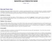
 It is not always possible to tackle the sources of local QRM. What remains is trying to reduce the noise level by means of your antenna system. Learn how to reduce QRM and understand how cancell noises.
 -
 137 kHz propagation analysis details ground wave and sky wave mechanisms, drawing heavily from **CCIR Rec. 368-6** for ground wave field strength predictions and **CCIR Rep. 265-7** for sky wave modeling. The resource presents field strength values for 1 W ERP at varying distances, considering ground conductivity and permittivity for ground wave, and ionospheric height (70km daytime, 90km nighttime) for sky wave. Key factors like ionospheric focusing (factor "D"), reflection coefficient ("RC"), and antenna ground pattern factors ("Ft", "Fr") are quantified for 137 kHz, enabling calculation of sky wave field strength. Practical coverage ranges are derived for 137 kHz, showing useful ground wave coverage up to 1600 km over seawater and 1100 km over average ground, assuming a -9 dBuV/m noise floor. Sky wave coverage extends beyond 2200 km during night-time and winter daytime, but is negligible during summer daytime at solar minimum. The document also compares ground wave and sky wave strengths, identifying crossover distances at 550 km (night-time), 750 km (winter daytime), and 1250 km (summer daytime), where interference fading can occur. Adjustments for solar maximum conditions are provided, indicating 2-11 dB higher sky wave values depending on distance and season.
 -
 Gold Line, a manufacturer, provides a range of professional audio test and analysis equipment, including specific products like the **ZM1 Impedance Meter**, which is relevant for amateur radio operators needing to characterize antenna systems. The site also lists various noise sources and microphones, such as the TEF04 Mic, indicating a focus on audio signal integrity and measurement. The resource details contact information for repairs, calibration, quotations for specific products like the ZM1 and ZM1P, and technical support, with distinct email addresses and phone numbers provided for each function. This structured contact approach facilitates direct engagement with the appropriate department for specific inquiries. Operational changes effective March 1, 2019, are noted, directing users to VLDESIGN for repair and calibration, and to Partha Chen for ZM1/ZM1P quotations. Louis Pittsley is designated for technical support, with a general inquiry phone number also available, outlining the company's support infrastructure.
 -
 Mobile RFI, often manifesting as persistent noise in the receiver even with the antenna disconnected, frequently originates from the vehicle's power supply system. This guide details systematic troubleshooting steps, beginning with isolating the radio from the car's 12-volt supply to confirm the power system as the noise source. It emphasizes the critical importance of drawing power directly from the battery using **heavy gauge wire**, bypassing the fuse block to leverage the battery's natural capacitance for RFI suppression and ensuring a solid RF ground. Proper routing of power lines through the firewall is also covered, advocating for dedicated grommeted holes to prevent inductive coupling from other wiring harnesses. The article stresses the necessity of fusing both positive and negative leads from the battery, a crucial safety measure to prevent damage to the rig and mitigate high-current risks should the battery's engine block ground become compromised during service. Addressing **alternator whine**, a common high-pitched noise that varies with engine speed, the resource suggests checking battery connections and the alternator-to-battery harness for looseness or corrosion. It also mentions the utility of adding an external RF noise suppression capacitor in parallel with the alternator's internal capacitor for enhanced filtering, and the effectiveness of commercially available in-line power supply filters.
 -
 Demonstrates the complete design and development process for a **Low Noise Microwave Amplifier** (LNA), beginning with conceptual design and progressing through prototyping. The tutorial series covers the initial stages of a single-ended first gain stage, focusing on critical parameters such as noise figure, gain, and stability. It systematically details the theoretical underpinnings and practical considerations for achieving optimal performance in microwave frequency applications. This resource provides a structured approach to LNA construction, enabling radio amateurs and RF engineers to understand the iterative steps involved in realizing high-performance receive-side amplification. It offers insights into component selection, impedance matching networks, and the measurement techniques required to validate design specifications, particularly for **microwave** band operation where noise performance is paramount.
 -
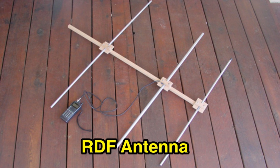 How to homemade antenna to be used with a handheld on the aircraft band to locate noise sources
 -
 Fifty-three digital modes, including PSK31, RTTY, and JT65, are explored in this resource, providing detailed descriptions of their underlying technologies and typical use cases. It covers error correction methods like ARQ in PACTOR and FEC in JT65, alongside modulation schemes such as FSK and PSK. The content highlights the evolution of digital communication from traditional TNC-based systems to modern sound card implementations, emphasizing the role of personal computers in advancing these modes. Specific modes like AMTOR, PACTOR, and G-TOR are discussed, noting their baud rates and error correction capabilities. For instance, AMTOR operates at 100 baud, while PACTOR offers 200 baud with Huffman compression. The article also delves into newer modes like MFSK16, which uses 16 tones and continuous Forward Error Correction, and Olivia, capable of decoding signals 10-14 dB below the noise floor. Each mode's bandwidth, speed, and resilience to propagation challenges are examined, such as MT63's 1 KHz bandwidth and 100 WPM rate, or Hellschreiber's 75 Hz bandwidth and 35 WPM text rate. The resource also lists predominant USA HF digital frequencies for bands like 160, 80, and 40 meters, specifying segments for PSK31, RTTY, SSTV, and Packet. It includes links to freeware and shareware sound card software such as Digipan, FLDigi, and MixW, enabling amateurs to experiment with these modes.
 -
 NFM (for Noise Figure Meter) is a software application to assist Noise Figure measurement. NFM implements the method of Agilent application notes AN 57-1 and AN 57-2 for noise figure measurement, but with the addition of an adjustable attenuator after the noise source and between the DUT and instrument.
 -
 Designing and constructing a two-element receiving loop antenna array for HF operation involves specific considerations for achieving high directivity and noise reduction. This resource details a homebrew system comprising two 30-inch diamond-shaped loops, spaced 20 feet apart, which are fed through mast-mounted preamplifiers and passive signal combiners. The operational principle relies on adjusting phase delays between elements via precise _Belden 8241_ coaxial cable lengths, optimized for specific bands from 160m to 20m. Performance data, derived from _EZ-NEC_ modeling, illustrates consistent 90° azimuth-plane beamwidth and low take-off angles across the target bands, with _Receiving Directivity Factor_ (RDF) values comparable to a 300-foot Beverage antenna. The article presents detailed elevation and azimuth plots for 20m, 30m, 40m, 80m, and 160m, demonstrating the array's ability to provide strong response at low DX angles while also supporting _NVIS_ signals. Key components like the _DX Engineering RPA-1_ preamplifier and _DXE RSC-2_ signal combiner are discussed, alongside the importance of impedance matching to preserve antenna patterns. The construction emphasizes self-contained elements that do not require ground radials, offering a compact solution suitable for suburban environments and stealth installations, with a focus on optimizing receive performance independently from transmit antennas.
 -
 The resource, "Conventional Use of Transmission Line," meticulously details the operational principles of transmission lines, emphasizing the Transverse Electromagnetic (TEM) mode of energy transfer. It clarifies that for a line to function purely as a transmission line, all currents must be confined internally, with external fields ideally zero. The discussion differentiates between balanced and unbalanced lines, asserting that while both require equal and opposite currents within the conductors, the key distinction lies in the voltage relationship of each conductor to the surrounding environment. It highlights that a good antenna pattern does not inherently confirm proper feeder balance, and that common-mode currents can lead to RF in the shack and increased noise levels, even without pattern distortion. The article further explains that a transmission line can become a radiating conductor if energy is applied in a non-TEM mode, leading to common-mode issues. It cites classic texts like Jordan and Balmain's "_Electromagnetic Waves and Radiating Systems_" and Kraus's "_Antennas_" to support its definitions of TEM mode operation. The content also explores non-transmission line applications of parallel or concentric conductors, such as _coaxial dipoles_ and _folded dipoles_, which intentionally operate in non-TEM modes for antenna functionality. The author, _W8JI_, stresses that simply measuring equal currents is insufficient to confirm a balanced feeder; phase and voltage balance to ground are equally critical.
 -
 Radio Astronomy Supplies astronomy products since 1994 including radio telescopes, LNA's, noise callibration source, books, videos.
 -
 Clarifies the intricate process of calibrating the _Elecraft K2_ dial, addressing common user challenges and lively discussions on the Elecraft reflector. Wilhelm, W3FPR, dissects the K2's PLL synthesizer design, chosen for its low phase noise, kit-friendly duplication, and cost-effective components. The resource emphasizes the critical role of the 4000.000 kHz reference oscillator's accuracy during CAL PLL, CAL FIL, and CAL FCTR functions, noting its dependence on temperature and crystal stability for optimal performance. Explaining the K2's frequency display, the document reveals it relies on microprocessor-driven look-up tables generated by CAL PLL for VFO values and CAL FIL for BFO values. In SSB and RTTY, these combine, while CW and CWr modes also factor in the sidetone pitch. The author details inherent limitations, such as the 10 Hz increment resolution of the dial and varying PLL step sizes—from 3 Hz on 160 meters to 10 Hz on 10 meters. BFO increments range from 20 to 35 Hz, collectively limiting practical dial accuracy to within **20 Hz** with diligent effort, or **30 Hz** for a slightly less demanding task. The guide outlines a four-step calibration procedure: setting the reference oscillator, running CAL PLL, running CAL FIL, and setting all BFOs. It highlights the _N6KR Method_ as a particularly easy and accurate approach, requiring only the K2 and a known frequency source like WWV for zero-beating, eliminating the need for external test equipment.
 -
 Mitigating impulse-type noise, a common challenge in the **HF radio spectrum**, often requires specialized processing before the signal reaches the transceiver's receiver stages. The NR-1 addresses this by functioning as an RF interference removal device, specifically a noise blanker, targeting transient noise sources. Its operational range extends from 1.6 MHz to beyond 70 MHz, making it suitable for various amateur radio bands and general shortwave listening applications. Unlike QRM eliminators or X-phasers, the NR-1 does not require a separate noise antenna for its operation, simplifying its integration into existing station setups. The device's design focuses on wideband performance, allowing its use both within and outside the allocated amateur radio frequencies. Documentation detailing its operation is available, providing insights into its technical specifications and deployment. This unit is a hardware product, conceptualized and implemented by SV3ORA.
 -
 This article discusses how volume reduction can help in the reception of weak signals by reducing the noise level. It is commonly known that reducing the volume also reduces the background noise, and especially in the reception of weak digital signals it can be beneficial
 -
 QRM.guru has been developed to assist radio hams in dealing with RF noise. This is an educational and reference resource.
 -
 Hamradio_copilot is an open-source tool designed for DXers and contesters who need real-time situational awareness. It is ideal for operators who want to visualize propagation trends instantly rather than scrolling through raw text streams of cluster spots. Rally acting as a copilot for your station, this tool transforms raw data into actionable intelligence. By visualizing Signal-to-Noise Ratios (SNR) across different bands, it helps operators make quick decisions on which band to prioritize or where to point their antennas, effectively showing not just who is on air, but where the propagation is currently open from your location. This is a fantastic information for avid contesters. The software aggregates data from two primary services: - Reverse Beacon Network (RBN) via Telnet. - PSK Reporter via MQTT feeds. It processes this data to generate a comprehensive HTML report featuring SNR heatmaps and statistical breakdowns by ITU Zone. Users can filter data by specific zones or country codes (ADIF), analyze historic time ranges, and optionally integrate solar weather data. The complete source code is available on GitHub, allowing for community customization. It is written in Python and uses SQLite for data management.
 -
 A small magnetic loop antenna, often employed by hams facing antenna restrictions or high local RFI, offers a compact solution for HF operation. This resource details the construction of a foldable magnetic loop designed for the 40m through 17m bands, emphasizing its high-Q factor and _Faraday coupling_ for effective noise rejection and narrow-band filtering. The guide outlines material selection, advocating for copper over aluminum to maximize efficiency, and provides insights into the physics governing its operation, including impedance matching and resonance principles. Practical application of this antenna design is particularly beneficial for QRP enthusiasts and portable operators seeking a stealthy, high-performance antenna. The construction process includes specific details for a 1-meter diameter loop, a 140pF variable capacitor, and a _gamma match_ for impedance transformation. Performance comparisons suggest that while a full-size dipole might offer slightly better gain, the magnetic loop's ability to mitigate local noise often results in a superior signal-to-noise ratio, making it a viable option for challenging RF environments.
 -
 The most basic form of repeater receives communication on one frequency and re-transmits it on a different frequency, a process known as duplex communication. This capability significantly extends the range of handheld and mobile radios, as repeaters are typically situated at elevated locations with high-gain antennas and greater transmit power. Repeaters commonly operate with FM modulation on the VHF (30 MHz – 300 MHz) and UHF (300 MHz – 3 GHz) amateur bands, which are ideal for portable and mobile devices. Access to repeaters is often controlled by a CTCSS or PL tone, an inaudible signal that prevents the repeater from retransmitting background noise. This mechanism ensures efficient use of the frequency and prevents illegal continuous transmission. Canadian regulations, for instance, require an Advanced amateur radio license and an available frequency within the band to set up a repeater, each assigned a unique call sign and transmit frequency. Configuring a radio for repeater use involves knowing the repeater's transmit frequency, its receive frequency offset (e.g., -600 KHz for VHF or +5 MHz for UHF), and the necessary CTCSS tone. The article references resources like Repeater Book for locating repeaters and provides practical examples for initiating and concluding a basic repeater session, emphasizing clear identification and concise communication.
 -
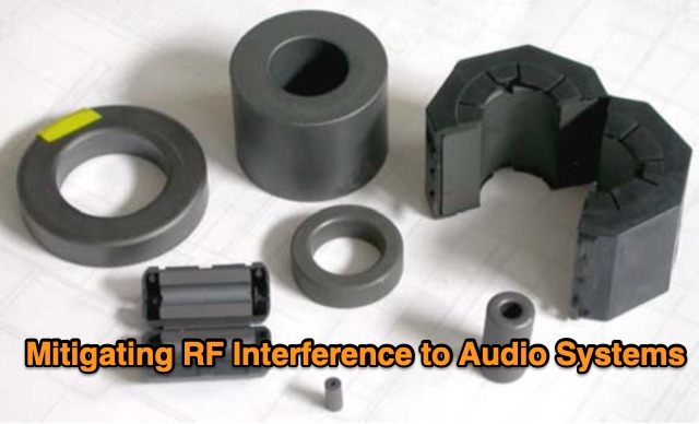 In this study, the author builds upon Muncy's research, demonstrating that radio-frequency current on cable shields affects audio systems through the "pin 1 problem" and shield-current-induced noise (SCIN). An enhanced equivalent circuit for ferrite chokes is proposed, addressing dimensional resonance and inductor self-resonance. Field tests confirm that chokes reduce interference across 500 kHz to 1,000 MHz. Guidelines for diagnosing and mitigating EMI from various sources are provided for product development and field installations.
 -
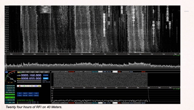 Demonstrates the application of Software-Defined Radios (SDRs) as effective tools for conducting Radio Frequency Interference (RFI) site surveys. The resource details the methodology for capturing and analyzing RFI, specifically focusing on the 80-meter band over a 24-hour period. It outlines the setup of an SDR-based survey tool, utilizing software like _S-Meter Lite_ and _Spectrum Lab_ to visualize and quantify noise sources. The article emphasizes the SDR's wideband capabilities, which allow for comprehensive identification and documentation of RFI across broad frequency ranges, crucial for effective mitigation strategies. The analysis presents practical results, illustrating how continuous monitoring can reveal intermittent RFI sources that might otherwise go undetected. For instance, the survey identified noise peaks exceeding **S9+20dB** on 80 meters during specific hours, correlating with local appliance usage. The methodology provides a repeatable process for hams to characterize their local noise floor, enabling targeted RFI suppression efforts and improving weak-signal reception, particularly for DXing and contesting.
 -
 This resource details the construction and performance of a compact broadband magnetic loop antenna designed for portable receiving applications with devices like the _ATS MiniRadio_. The antenna utilizes approximately 3 meters of 0.5–1 mm copper wire wound in two turns on a rhomboidal wooden frame, measuring 50 cm by 70 cm. It connects via a modified 9:1 unun, where the primary center tap is isolated from ground to improve common-mode noise rejection. The design provides untuned operation across a frequency range from the longwave band up to approximately 25 MHz. Performance characteristics include observable directivity for noise suppression and the ability to connect directly to a radio or via a 50 coaxial cable for remote operation. The article specifies the unun's 3:1 turns ratio and its SMA output for connectivity. The methodology focuses on practical construction and observed reception quality.
 -
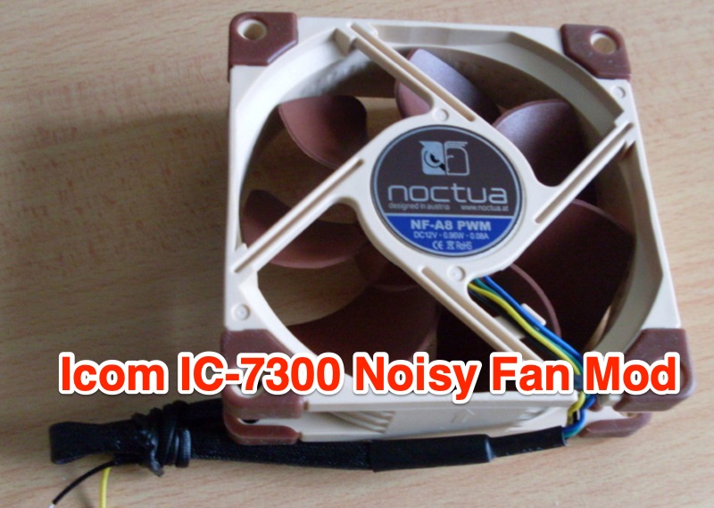 The Icom IC-7300 transceiver's stock cooling fan, a 12VDC unit typically run at 6VDC with a 10VDC transmit kick, is often perceived as noisy. This modification replaces the original fan with a **Noctua NF-A8 PWM** fan, which is described as "silent" even during the initial 10V transmit kick. The resource provides specific wiring details, noting black for negative and yellow for positive connections, and suggests using readily available 2-pin fan plugs for a clean installation. This fan replacement significantly reduces operational noise, improving the user experience of the IC-7300. The Noctua NF-A8 PWM fan is available for under £20 in the UK, making it an accessible upgrade. The modification is presented as a straightforward process, enhancing the rig's acoustic profile without compromising cooling efficiency, based on the experience of Bjorn Eklund, **SM7IUN**.
 -
 The YIG Tuned Oscillator (YTO) is the only direct signal source to provide multi octave tuning bandwidths in excess of 10 GHz. Common tuning ranges are from 2-10 GHz, 8-18 GHz and 10-20 GHz. YTO is are also known for their superior phase noise and exceptional tuning linearity.
 -
 The Olivia digital mode, a **Multi-Frequency Shift Keying (MFSK)** radioteletype protocol, is specifically engineered for robust communication under difficult propagation conditions on shortwave radio bands from 3 MHz to 30 MHz. Developed by Pawel Jalocha in 2003, Olivia signals can be decoded even when the noise amplitude exceeds the digital signal by over ten times, making it highly effective for transmitting ASCII characters across noisy channels with significant fading and propagation phasing. Early on-the-air tests by Fred OH/DK4ZC and Les VK2DSG on the Europe-Australia 20-meter path demonstrated intercontinental contacts with as little as one-watt RF power under favorable conditions. Common Olivia modes are designated as X/Y, where X represents the number of tones and Y is the bandwidth in Hertz, with examples including 8/250, 16/500, and 32/1000. The resource clarifies that Olivia, unlike some other digital modes, produces a constant envelope, allowing RF power amplifiers to achieve greater conversion efficiencies and making it less prone to non-linearity. Operators are advised that **Automatic Level Control (ALC)** can be set higher than no meter movement for MFSK modulation, as long as it's not driven past its high limit, contrary to common misinformation about other digital modes. The Olivia community encourages voluntary channelization on suggested calling frequencies, such as 14.0725 MHz for 8/250, to facilitate initial contacts, especially for signals below the noise floor. The Olivia Digital DXers Club provides links to Groups.io, Facebook, and Discord for community engagement and offers details on QSO parties.
 -
 This article About Noise offers a clear, non-mathematical explanation of noise in telecommunications, making it accessible to radio amateurs. It categorizes noise into fundamental and intermodulation types, detailing sources like thermal, shot, and cosmic noise. The article effectively highlights noise impact on receivers and introduces key metrics like Noise Figure and Signal-to-Noise Ratio (SNR). While comprehensive, it remains digestible, balancing technical depth with simplicity. A great resource for understanding radio noise fundamentals without complex equations, though a more detailed discussion on mitigation techniques would further enhance its value.