Search results
Query: transmitter design for 8
Links: 53 | Categories: 1
Categories
-
 Monitoring shortwave broadcast stations effectively requires accurate schedule information to identify transmissions. This online utility offers a straightforward, graphical interface designed to search for and display current shortwave radio broadcasting schedules. Users can precisely filter results by frequency, specific language, broadcaster, time of day, and even by shortwave band, which simplifies the process of pinpointing desired content. The database, last updated on March 26, 2023, details station callsigns (e.g., BBC), start and end times in UTC, days of the week, broadcast language, transmitter power in kilowatts, and azimuth. Crucially, it includes the precise geographical coordinates of transmitter sites, such as Woofferton in the UK or Al Seela in Oman. This data is invaluable for predicting signal paths and optimizing antenna direction for improved reception, a key consideration for serious SWLs. For instance, a search for BBC English broadcasts at 21:04 GMT quickly reveals multiple active frequencies like 17780 kHz from Woofferton, offering a clear overview of current transmissions. The tool processes queries rapidly, returning results within seconds, demonstrating its efficiency for broadcast listening enthusiasts seeking timely information.
 -
 This article describes how to make a quadrifilar helix (QFH) antenna easily, from inexpensive materials: uPVC plumbing pipe and RG-58U co-axial cable. A low-cost, easy-to-build Quadrifilar Helix (QFH) antenna for weather satellite reception using uPVC plumbing pipe and RG-58U coaxial cable. Unlike traditional designs requiring copper pipe and plumbing skills, this approach enables construction with basic tools and minimal technical expertise. The antenna's shorter, wider proportions favor higher elevation angles, reducing interference from horizon-level pager transmitters. Electrical connections are simplified at the antenna's apex, with the coaxial cable forming the radiating elements. Testing demonstrated consistent signal strength throughout satellite passes, proving effective weather satellite reception is achievable without precision engineering to sub-millimeter tolerances.
 -
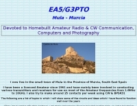 Presents a collection of homebrew amateur radio projects and circuit ideas developed by EA5/G3PTO, a licensed operator since 1961. The resource details various transmitters and receivers constructed for frequencies ranging from 1.8 MHz to 10 GHz, emphasizing CW and BPSK31 operation. Specific projects covered include a "Bombproof 7Mhz Receiver" and several keying circuits, providing insights into designs that have proven effective over decades of use. The site also integrates personal photography, showcasing scenes from the West of England and Southeast Spain, reflecting the author's interest in connecting with other amateurs and visualizing their locations. Additionally, it offers a curated list of links to other home construction sites and DX information, serving as a hub for DIY enthusiasts and DXers. The content is distinctively personal, blending technical project documentation with a broader view of the amateur radio lifestyle and community engagement.
 -
 Presents a crystal-controlled CW transmitter design for the 40-meter band, delivering 5 to 7.5 watts output power. The circuit innovatively employs an _IRF510_ power MOSFET in the final amplifier stage, diverging from conventional bipolar transistors. This design offers high gain, nearly 90% efficiency, and robust resistance to high SWR, allowing 30-second key-down operation into an open circuit without damage. A critical aspect is the precise adjustment of the MOSFET gate bias via a 10K trimmer pot, _R10_, to maintain quiescent current between 5 and 10 mA, preventing thermal runaway inherent to bipolar devices. The prototype was constructed on a _Radio Shack universal board_ and achieved immediate operational success. The design requires a 15-volt Zener diode to protect the MOSFET gate from overvoltage. Component sourcing information is provided, including specific crystal frequencies (7.040 MHz or 7.122 MHz) available from _Dan’s Small Parts & Kits_ or Doug Hendricks. The fixed frequency can be slightly adjusted with a trimmer capacitor. A complete bill of materials, including resistor values, capacitor types, toroid specifications, and transistor part numbers, is detailed, alongside a clear schematic diagram.
 -
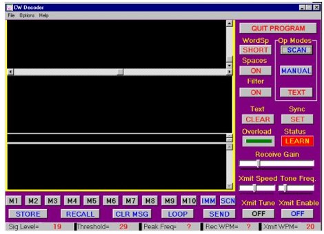 The CW Decoder program facilitates copying Morse code with a computer, displaying decoded CW as text, and generating a sidetone. It incorporates a spectrum display of the audio, allowing operators to select a specific audio frequency for decoding via a sliding cursor. This utility also enables keyboard-based transmitter keying, supporting full CW break-in operation for efficient QSO management. Developed by WD6CNF, the software is a Windows-compatible application designed to assist amateur radio operators in their CW activities. Its features cater to both decoding received signals and transmitting via keyboard input, streamlining the CW operating experience. Functionality includes real-time audio analysis and signal processing, providing a visual representation of the CW signal. The program's integrated keying capability offers a direct interface for transmitting, enhancing its utility as a comprehensive CW station tool.
 -
 Constructing a Lindenblad antenna for 137MHz NOAA satellite reception involves specific design considerations for optimal performance. The resource details the use of 4mm galvanised steel fencing wire, 300-ohm television ribbon cable, and wood/plastic components for the antenna structure. Key dimensions for a 137.58MHz-resonant antenna are provided, derived from the ARRL Satellite Handbook, specifying s, l, w, and d as 42, 926, 893, and 654mm respectively. The antenna is designed for Right Hand Circularly Polarised (RHCP) signals, requiring the four folded dipole elements to be tilted clockwise by 30 degrees. A significant aspect covered is impedance matching between the antenna's 75-ohm impedance and a typical 50-ohm receiver input. A twelfth-wave matching transformer, constructed from 117mm sections of 50-ohm RG-58 and 75-ohm RG-59 coax with a 0.66 velocity factor, is described. The article also addresses coaxial cable and connector selection, recommending 75-ohm Type-N connectors for RG-6 cable in professional setups and F56/F59 connectors for general use, while strongly advising against PL-259/SO-259 connectors for VHF. Strategies for mitigating Radio Frequency Interference (RFI) are discussed, including antenna placement to shield from local TV transmitters and the use of commercial or DIY band-pass filters, such as cavity resonators or helical notch filters, along with ferrite chokes on coaxial cables. Antenna orientation is explored, noting the Lindenblad's 'cone of silence' directly overhead and its maximized sensitivity towards the horizon. An experimental vertical tilt of 90 degrees is presented as a method to improve overhead reception and reduce interference from strong horizontal signals, particularly relevant in high RFI environments like the Siding Spring Observatory site.
 -
 RF Path design software, tower coverage mapping software to evaluate radio transmitter sites, predict and simulate radio coverage, plan land mobile radio or cellular systems. Commercial RF coverage mapping software by Softwright llc.
 -
 FDLog, a Python-based freeware application, addresses the challenge of synchronized logging for multi-station Field Day operations. It facilitates real-time data sharing across a wireless network, enabling operators to monitor band status and active transmitters at a glance. The software's input system is optimized for minimal keystrokes, streamlining the logging process during intense contest periods. Key features include database synchronization over a wireless network, ensuring all connected computers maintain identical log data. FDLog also incorporates a time synchronization function, designed to keep client programs within a second of a designated master machine, mitigating issues previously encountered with NTP. This internal clock sync can be optionally disabled if not required by the operating setup. Developed initially on Windows 2000, FDLog has demonstrated compatibility with _Linux_ and _macOS_ environments, though some font rendering issues may occur on the latter. The program assists in preparing the ARRL Field Day entry form, simplifying the submission of contest results. User feedback and ARRL rule changes drive ongoing development, with a discussion list available for community support and input.
 -
 One specific challenge in the KazShack, operating Single Operator Two Radios (SO2R), involved sharing a K9AY receive antenna between two transceivers without direct RF connection or manual feedline swapping. The solution, detailed in this project, adapts the **W3LPL RX bandpass filter** design to split 160m and 80m signals, feeding them to separate radio inputs while maintaining isolation. This approach also addresses the issue of strong broadcast band interference from a nearby 50KW WPTF transmitter on 680kc. The construction utilizes T-50-3 toroids and NP0 ceramic capacitors, built in a "dead bug" style on copper clad board. Each band's filter coils are identical and resonated to the desired frequency using an MFJ-259 antenna analyzer. A single DPDT relay, controlled by a remote toggle switch mounted on an aluminum panel, facilitates quick band switching between radios, simplifying low-band operations. While some signal loss is noted, the expected lower noise levels from the receive antenna are anticipated to compensate, potentially reducing the need for constant volume adjustments during toggling between transmit and receive antennas.
 -
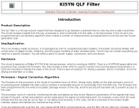 The QLF filter is a microprocessor based interface designed to go between a standard Morse code key and a radio transmitter
 -
 Examines the historical landscape of "boat anchor" amateur radio equipment manufacturers, focusing on the technical innovations and market dynamics that shaped the industry from the pre-WWII era through the transition to SSB. It details the origins and key product lines of prominent U.S. companies like _Collins Radio Company_, _Central Electronics_, and _Barker & Williamson_, highlighting their contributions to receiver and transmitter design. The resource contrasts early AM technology with the advent of SSB, explaining the circuit changes required in receivers and the complete rethinking needed for transmitters. It discusses the impact of military contracts on company survival and the eventual shift towards smaller, self-contained transceivers. Specific examples, such as the _Collins R-390/URR_ receiver and the _Central Electronics 100V/200V_ broadband transmitters, illustrate the engineering prowess and design philosophies of the era, offering insights into their operational characteristics and enduring appeal among collectors.
 -
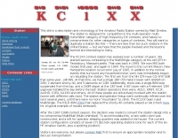 Amateur Radio Station owned by Matt Strelow. The station is designed for competition in the multi-operator multi-transmitter category of high-frequency DX contests. Running with 7 towers 6 rotators, 8 beverage listening antennas, and 4 spotting verticals
 -
 TX RX Systems Inc. offers a robust catalog of RF conditioning products, including **transmitter combiners**, receiver multicouplers, and various RF filters. Their extensive experience, spanning over 45 years in the RF and Land Mobile Radio (LMR) industries, underpins their specialized offerings. They provide solutions for in-building RF coverage, repeater systems, and general RF management, catering to the demanding requirements of professional radio communications. Their product line features **bidirectional amplifiers (BDAs)**, signal boosters, and cavity filters, essential components for optimizing radio system performance. The company emphasizes reliable solutions, leveraging decades of field-proven expertise in designing and manufacturing critical RF infrastructure. From duplexers to cell enhancers, TX RX Systems focuses on delivering high-quality RF components and integrated systems designed to ensure clear and consistent radio signal integrity across diverse operational environments.
 -
 The NCDXF/IARU International Beacon Project operates a worldwide network of 18 high-frequency radio beacons, continuously transmitting on 14.100, 18.110, 21.150, 24.930, and 28.200 MHz. These beacons, initially launched in 1979 with a single station and expanded to the current 18-beacon system in 1995, provide reliable signals for both amateur and commercial users to assess current **ionospheric propagation** conditions. The system's design, construction, and operation are managed by volunteers, covering hardware and shipping costs. The resource details the evolution of the beacon network, including the transition from Kenwood TS-50s transmitters to Icom IC-7200 radios with a new controller design implemented in 2015. It explains how listening for these 100-watt signals, transmitted to vertical antennas, allows operators to determine band openings and optimal propagation paths globally. The content also references three QST articles providing historical context and technical specifics of the beacon project. Practical information includes methods for identifying transmitting beacons via a schedule or specialized software like FAROS and Skimmer, which integrates with the **Reverse Beacon Network** for automated monitoring.
 -
 For amateur radio operators engaged in **radio direction finding** (RDF) and **transmitter hunting** (T-hunting) activities, this resource provides a catalog of printed circuit boards (PCBs) for constructing various DF and foxhunt-related projects. The offerings include PCBs for 80-meter fox transmitters and receivers, UHF fox transmitters with audio recording capabilities, and several designs for general-purpose radio direction finders. Specific projects like the "Simple 80M ATX-80 Transmitter" and the "N0GSG DSP Radio Direction Finder" are listed, along with attenuator boxes and specialized components for Doppler DF systems. The catalog details PCBs for projects published in prominent amateur radio magazines such as *73's*, *CQ*, *QST*, and *PE*, indicating their origin and design pedigree. For instance, the "Montreal Fox Controller" is sourced from the *Homing-In* column by Joe Moell, K0OV. The resource also lists components for advanced Doppler DF systems, including main boards, LED display boards, and antenna switch boards, with options for programmed PIC microcontrollers. Pricing for each PCB is provided, allowing hams to acquire the necessary components for their DIY RDF endeavors.
 -
 Hidden transmitter hunting, often called fox hunting or Amateur Radio Direction Finding (_ARDF_), presents a unique challenge for radio amateurs. This resource details the _PicCon_ controller, a specialized device designed to automate the transmission of signals for such events. It integrates with a standard radio transceiver, functioning similarly to a packet radio TNC, by controlling the Push-To-Talk (PTT) line and injecting audio tones or modulated CW Morse code into the microphone input. The _PicCon_ unit is field-programmable using DTMF tones received via the radio, storing all settings in EEPROM for power-off retention. Its compact design and low power consumption (a few milliamps from a 7-35VDC source) make it suitable for remote deployment. An onboard LED indicates operational status, and a push-button allows manual start/stop of transmissions without DTMF. Typically supplied as a kit, _PicCon_ includes a PCB, components, and a comprehensive manual (available in HTML, RTF, and PDF formats). The kit provides a six-conductor interface cable, but users must supply radio and power plugs due to varied configurations. Byon, _N6BG_, developed this controller, which is available from the Byonics website.
 -
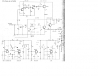
 Presents a QRP AM/CW transmitter project specifically designed for the 10-meter band, utilizing a crystal oscillator and a collector-modulated AM oscillator. The design employs a 2N2219(A) transistor in a Colpitts configuration, generating 100 to 350 mW of RF output power depending on the 9-18 Volt supply voltage and modulation depth. Frequency stability is maintained by a 28 MHz crystal, with fine-tuning possible via a Ct1 trimmer capacitor for approximately 1 kHz adjustment. The resource details the RF oscillator stage, implemented with a 2N2219 NPN transistor, emphasizing frequency stability and low power dissipation. It also covers the amplitude modulation stage, managed by a 2N2905 PNP transistor, which impresses audio information onto the carrier. Selective components (C3, C4, C7, C5) enhance voice frequencies within a +/- 5 kHz bandwidth, and modulation depth is controlled by R2 and R3. The project includes a 3-element L-type narrow bandpass filter (Ct3, L3, C10) to suppress harmonics and ensure a clean output signal. The project provides a complete schematic diagram, a comprehensive parts list including specific capacitor, resistor, and inductor values, and construction notes for the coils (L1, L2, L3). It also offers practical advice on enclosure requirements, suggesting an all-metal case or a PVC box with graphite paint for RF shielding. Operational parameters such as current draw (27mA@9V to 45mA@16V) and input impedance (50 Ohms) are specified, alongside guidance on antenna matching and the importance of a valid amateur radio license for 10-meter band operation.
 -
 The information in this article has come from many amateur sources, the most notable was from WA6TEY (sk 1985) Ray Frost, who was a pioneer of VHF Quad designs and one of the best Southern California Transmitter Hunters. Ray built hundreds two meter quads in single and paired configurations as well as his famous mobile radio direction finding quad.
 -
-
 Antenna tuners are crucial for matching the impedance of antennas to the 50 ohm output impedance of transmitters. The _LDG Z-11 Pro_ is an automatic antenna tuner designed to handle up to 125 watts, making it suitable for a wide range of amateur radio applications. Its compact form factor allows it to pair well with transceivers like the _FT-857D_, providing a portable solution for operators who frequently change locations or setups. The tuner covers the 80 through 6 meter bands, offering a broad impedance match capability. Although it struggles with some loads, it performs well with typical ham antennas, even managing to load an 80 meter dipole on 6 meters. One of the standout features of the _Z-11 Pro_ is its 8000 memory slots, which enable it to remember successful matches and quickly retune when revisiting frequencies. This memory function significantly reduces tuning time, often to less than half a second. The unit is well-constructed, with improved pushbuttons and a sturdy metal case that offers good shielding. However, users should be aware of potential RFI issues and the lack of a power switch, which requires disconnecting the power cord to turn off the unit completely. Overall, the _LDG Z-11 Pro_ is a user-friendly and cost-effective tuner, offering advanced features that enhance its utility in various amateur radio setups.
 -
 This graphics-intensive program designs and analyzes active quadrature ("90-degree") networks for use in SSB transmitters and receivers.
 -
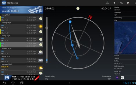 The _ISS Detector_ Android application, with over 5 million downloads, offers precise predictions for visible passes of the International Space Station. It notifies users minutes before an overhead pass, integrating local weather conditions to ensure optimal viewing opportunities. The core functionality focuses on the ISS, but in-app purchases extend its capabilities to track other celestial and artificial objects. Optional extensions, available via in-app purchase, allow users to monitor dozens of amateur radio and weather satellites, providing real-time transmitter information and Doppler frequencies. Additional extensions cover _Starlink_ satellites, the _Hubble Space Telescope_, rocket stages, bright satellites, comets, and planets, expanding the scope beyond the ISS to a broader range of observable space phenomena. The app's interface is designed for ease of use, displaying pass times, directions, and elevation. It adapts predictions based on the user's GPS location, ensuring accurate local forecasts. The latest update, dated April 3, 2026, includes corrections for magnitude values and various speed and stability optimizations.
 -
 The 80 metre fox-or/test transmitter is a small low power transmitter which is designed to be used as an alignment aid for running up 80 metre foxhunt or ARDF receivers. It is also usable as a micro transmitter for fox-or-ing events.
 -
 The requested resource, identified by the title "Micamold XTR" and description referencing the _Micamold XTR-1_ transmitter manufactured in 1948 by MICAMOLD Radio Corp., is currently unavailable, returning a 404 error. This indicates the specific content detailing the vintage radio equipment, its technical specifications, or historical context is not present at the given URL. The original intent was likely to provide information on this particular piece of antique radio gear, potentially covering its design, operation, or restoration aspects relevant to collectors and enthusiasts of historical amateur radio equipment. The absence of the page means no technical details, schematics, or operational insights regarding the _XTR-1_ transmitter can be retrieved. Users seeking information on this specific "boat anchor" radio would need to pursue alternative sources or attempt to contact the original website owner directly, as suggested by the QSL.net error message. The QSL.net platform, which hosts over 30,000 individual amateur radio websites, provides free services but does not maintain the content of individual hosted pages.
 -
 The article, "Using 75 Ohm CATV Coaxial Cable," details methods for employing readily available 75-ohm CATV hardline in standard 50-ohm amateur radio setups. It addresses the inherent impedance mismatch and practical considerations, such as connector compatibility, for hams seeking cost-effective, low-loss feedline solutions. The resource specifically contrasts common 50-ohm cables like RG-8, RG213, and _LMR-400_ with 75-ohm hardline, highlighting the latter's lower loss characteristics, particularly at VHF and UHF frequencies. It explores two primary approaches to manage the impedance difference: direct connection with an acceptable SWR compromise and precise impedance transformation. The direct connection method acknowledges that a perfect 1:1 SWR is not always critical, especially when using low-loss coax. For impedance transformation, the article explains the use of half-wavelength sections of coax to reflect the antenna's 50-ohm impedance back to the transmitter, noting its single-frequency effectiveness. It also briefly mentions transformer designs using toroid cores and a technique involving two 1/12 wavelength sections of feedline for broader bandwidth. The content further clarifies the concept of _velocity factor_ for calculating electrical versus physical cable lengths, providing a generic formula for precise length determination. It notes that while half-wave matching is practical for 10 meters and above, it can result in excessively long runs for lower bands like 160 meters, potentially adding **250 feet** of cable. The article also mentions achieving a usable bandwidth of 28.000 MHz up to at least **28.8 MHz** on 10 meters with specific transformation techniques.
 -
 A synthesized 2.3 GHz Amateur Television (ATV) transmitter design, conceived by Ian G6TVJ, is presented, targeting broadcast-quality video performance on the 13cm band and extending up to 2.6 GHz. The core of the design utilizes a commercial Z-comm Voltage Controlled Oscillator (VCO) that tunes from 2.2-2.7 GHz, providing a +10 dBm output and simplifying RF alignment. This VCO's stability, originally intended for narrowband applications, readily accepts high-frequency video modulation, contributing to the transmitter's robust performance. The exciter stage, incorporating a Mini Circuits VNA 25 MMIC amplifier, boosts the signal to +16dBm, while a Plessey SP4982 prescaler divides the output frequency for the synthesizer. The synthesizer employs a Motorola MC145151 CMOS parallel IC, favored over the common Plessey SP5060 for its superior video modulation characteristics and ease of programming without microprocessors. This choice addresses issues like LF tilt and distorted field syncs often seen with SP5060 designs, particularly when operating through repeaters or over long distances. The MC145151 divides the signal further, enabling precise frequency stepping, with programming handled by EPROMs for channel selection and LED display. The loop filter network, critical for video integrity, was developed through experimentation to prevent the PLL from reacting to video modulation, ensuring a clean transmitted picture. The transmitter incorporates a Down East Microwave commercial power amplifier module, delivering approximately 1.6W output, driven by the exciter through a 3dB attenuator. Construction involves surface-mount SHF components on micro-strip lines etched onto double-sided fiberglass board, housed within a tinplate box. The design boasts no AC coupling in the video path, preserving low-frequency response, a common failing in other ATV transmitters. Performance tests with a 50Hz square wave revealed no LF distortion, and a calibrated "Pulse & Bar" signal showed a near 100% HF response, demonstrating its capability for high-quality ATV transmissions.
 -
 For over 50 years, Communications Specialists Inc. has been a cornerstone in specialized radio frequency solutions, initially gaining prominence with their **CTCSS** and **DTMF** tone signaling products widely used in amateur radio repeaters and commercial two-way radio systems. My own experience with their tone boards in various repeater builds confirms their reliability and ease of integration, a testament to their engineering. The company's legacy in tone encoding and decoding is well-established, providing robust solutions for access control and selective calling. Beyond tone signaling, Com-Spec has diversified into niche markets, including wildlife telemetry, pet tracking collars, and specialized tracking systems for model aircraft and rocketry. Their product line features compact transmitters and receivers designed for specific tracking applications, demonstrating a commitment to precision and durability in challenging environments. While some legacy products are no longer available, Com-Spec continues to innovate, as evidenced by the new R-30M receiver, which ships within five days. This focus on specialized RF applications, from tracking Alzheimer's patients to law enforcement, highlights their unique position in the radio communications industry.
 -
 A cavity filter, often a critical component in _duplexer_ designs, functions as a sharply tuned resonant circuit, allowing only specific frequencies to pass while attenuating others. These filters are essential for maintaining signal integrity in environments where multiple transmitters and receivers operate simultaneously on closely spaced frequencies, such as in repeater stations. The article details how these filters, sometimes referred to as _notch filters_, achieve high Q factors, which are crucial for their performance. Understanding the principles of cavity filters is fundamental for any amateur radio operator involved in repeater operation or designing custom RF front-ends. The discussion covers the basic circuitry and operational characteristics that enable these devices to provide significant isolation, often achieving **-80 dB** or more between transmit and receive paths. This level of isolation is vital for preventing receiver desensitization and intermodulation distortion. Properly tuned cavity filters ensure that a repeater can transmit and receive simultaneously on different frequencies without self-interference, a common challenge in VHF/UHF operations.
 -
 A microprocessor based interface designed to go between a standard Morse code key and a radio transmitter. The circuit receives a signal from the key, processes it, and re-transmits it to the radio.
 -
 Documents the operational experiences and technical insights of amateur radio station VA3STL, offering a firsthand account of various on-air activities and equipment. The blog features a detailed narrative of a **QRP transatlantic QSO** on 12m SSB, achieving a 55 report with 10W to a mobile station in Italy using a homebrew 90ft doublet antenna. It also introduces the _Ten-Tec 539_ QRP HF transceiver, a 10W output rig covering 80m through 10m, designed for portable operations and featuring DSP and dual VFOs. The resource also delves into historical radio technology, specifically the "Gibson Girl" survival radio, an emergency transmitter operating on 500kHz (and later 8280/8364 kHz) with a hand-cranked generator and kite-deployed antenna. This section explores its origins from German designs and its use during World War II, including its distinctive curved shape for ergonomic hand-cranking. Further historical content includes a visit to Signal Hill in St. John's, Newfoundland, commemorating Marconi's reception of the first transatlantic radio signal in 1901. The post describes the Cabot Tower exhibit and the VO1AA station, highlighting the site's significance despite the thick fog during the visit. It also showcases a homebrewed _Marconi-style straight key_ by WB9LPU, crafted to celebrate the centenary of Marconi's achievement.
 -
 Station QRP presents various **circuit diagrams** for constructing low-power AM vacuum tube shortwave transmitters, catering to enthusiasts interested in vintage radio technology. The resource details schematics ranging from simple to more complex designs, enabling hams to build their own QRP AM transmitters for operation on frequencies like 6.925 kHz AM. It emphasizes the use of vacuum tubes, providing a technical foundation for understanding and replicating classic shortwave broadcasting methods. The content is geared towards those who enjoy the hands-on aspect of electronics and the unique characteristics of tube-based RF circuits. Building these transmitters allows operators to experience the nostalgia of early shortwave radio, with the site specifically mentioning a pioneer station on 6.925 kHz AM. The designs facilitate experimentation with low-power AM transmission, offering practical application for homebrew projects. The focus on QRP (low power) operation aligns with a segment of the amateur radio community that values efficiency and minimalist setups, providing a distinct alternative to modern solid-state transceivers.
 -
 This module is an analogue and digital SWR and power meter/monitor, designed to replace analogue SWR and power metering in an AM Transmitter project.
 -
 Fox Controller, designed by VE2JX and VE2EMM includes schematic diagram to build the transmitter.
 -
 This article introduces an Arduino-based QRP CW Transceiver designed for lower HF bands. The journey begins with the Wotduino, evolving from a keyer to a multi-mode beacon. The development includes a QRP transmitter and culminates in a receiver inspired by Roy Lewallen design. The transceiver, controlled through a control bus features a signal path, modulation, filtering, and adjustable frequency settings. Despite initial testing intentions, successful QSOs on 80 and 40 meters showcase its functional capabilities.
 -
 The _G3TSO_ Mobile Antenna Page details construction and tuning methods for mobile antennas operating across **10 to 160 metres**. The content describes a Hustler-based design, optimized for RF performance and vehicle speeds, featuring centre loading. For optimal operation on various bands, the loading coil placement requires clearance from the vehicle body. Antenna resonance is critical for efficient mobile operation. A mobile antenna's base impedance may be as low as 27 ohms, requiring specific matching to achieve maximum radiation, as a minimum SWR at the transmitter does not always indicate resonance or maximum output. Tuning involves physical adjustment of antenna length to achieve resonance at the operating frequency. The _G3TSO_ page outlines a tuning procedure utilizing a low-power signal source and a field strength meter to identify maximum radiation before impedance matching. Loading coil placement, either at the base, center, or top of the antenna, influences radiation efficiency and mechanical stability for mobile installations. Centre-loaded whips, such as the Hustler design, offer a compromise between efficiency and stability, often for single-band operation. Helically wound antennas, including those for **28 MHz**, may present base impedances around 17 ohms, resulting in a 3:1 SWR at resonance. Low resistance grounding at the antenna base is also specified for optimizing performance and minimizing RFI during mobile operation. DXZone Focus: Mobile | Any | Antenna Tuning | HF
 -
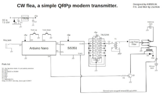 Reviving the spirit of early ham radio experimentation, the CW Flea is a contemporary Morse code transmitter. Utilizing an Arduino Nano, Si5351 clock generator, and innovative design, this open-source project offers simplicity, flexibility, and easy tuning for aspiring radio enthusiasts.
 -
 The 222 MHz Transverter project, based on Zack Lau's (W1VT) original July 1993 QEX magazine design, provides an IF of 28 MHz for both transmit and receive paths. Rick Bandla (VE3CVG) contributed supplemental notes and construction details, including modifications to achieve 10 mW output power from an initial 4 mW PEP. The design incorporates three distinct boards: a Local Oscillator (LO), a Transmitter (Tx), and a Receiver (Rx), with an estimated parts cost of just over $150 CDN, significantly less than commercial kits. Construction involves both through-hole and surface-mount components, with specific guidance on mounting MAV and MAR devices, grounding techniques, and component selection. The project details include parts lists, schematics for the LO, Tx, and Rx, and board layouts. Troubleshooting advice emphasizes sequential testing, starting with the LO, then Tx, and finally Rx, using a 194 MHz and 222.100 MHz capable FM handheld for signal tracing. Further enhancements are discussed, such as an optional Tx driver stage to boost output to 100 mW and the potential modification of a Motorola Maxor 80 PA for 222 MHz SSB/CW operation. The resource also covers practical aspects like power attenuation pads for IF radios (e.g., FT817) and considerations for enclosure design, including repurposing a Maxor 80 case. Performance reports indicate successful 70 km contacts with only 4 mW output.
 -
 This innovative antenna tuning unit (ATU) enables QRP operators to match their antennas without transmitting RF signals. Using a noise bridge technique instead of traditional transmit-and-tune methods, it achieves truly silent operation. The design incorporates an L-match network with switched inductors and variable capacitor, handling impedance matching from 3-30MHz. Operating from a 9V battery, it includes a built-in RF power meter and dummy load for QRP transmitter testing. The compact unit is particularly suitable for portable operations where minimal RF emissions during tuning are desired.
 -
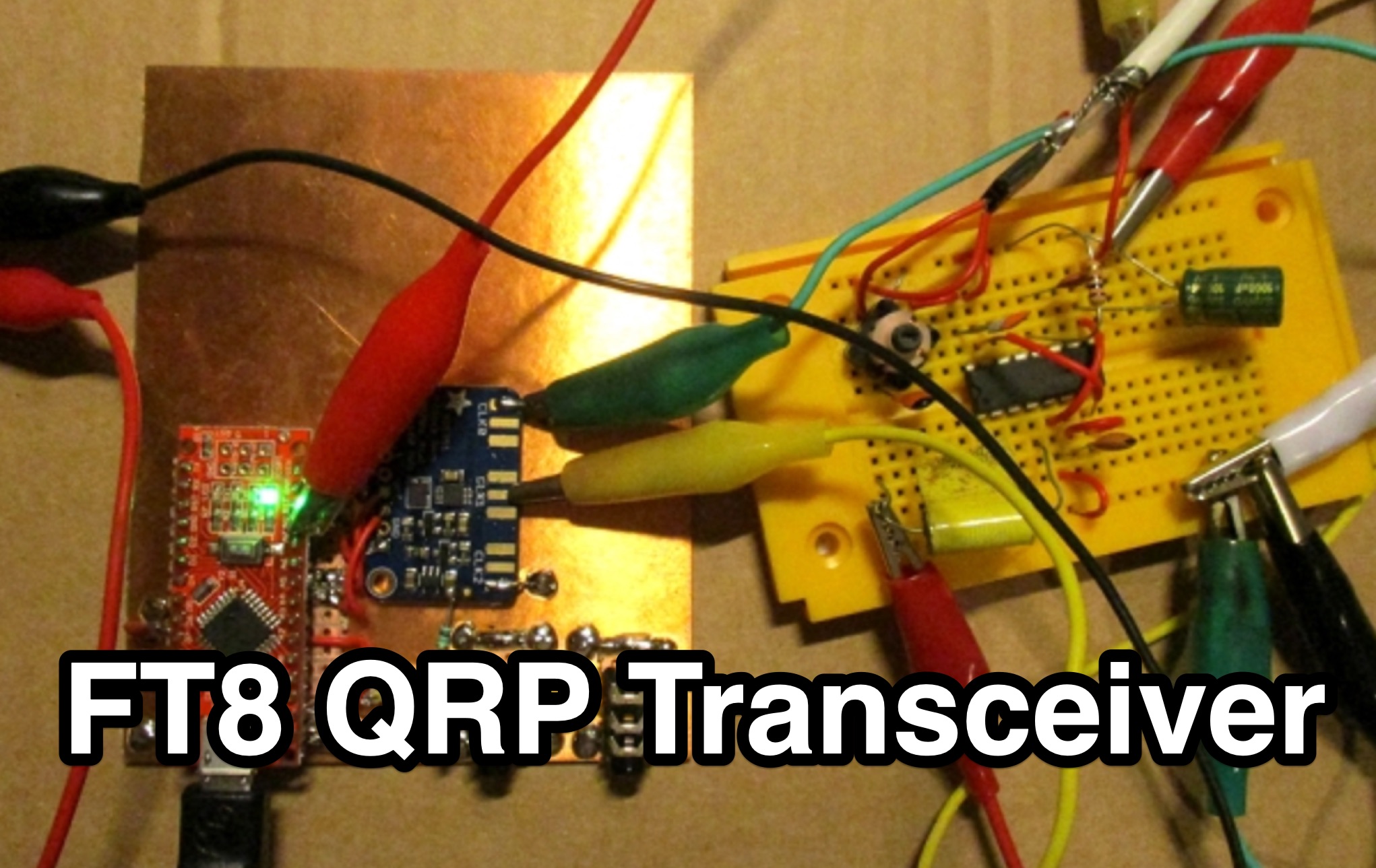 This page by Lajos Hoss, HA8HL, provides a detailed guide on how to build a simple direct receiver using FT8QRP CAT control support. The author shares his experience in making QSOs with FT8, WSPR, and JT65 modes during the Covid-19 lockdown. Modifications to the VFO, transmitter design using BD329 transistor Class A amplifier, and the challenges faced in achieving clean output signals within legal limits. This project is interesting for those hams that are interested in experimenting with DIY transmitter projects and understanding CAT control support for various amateur radio modes.
 -
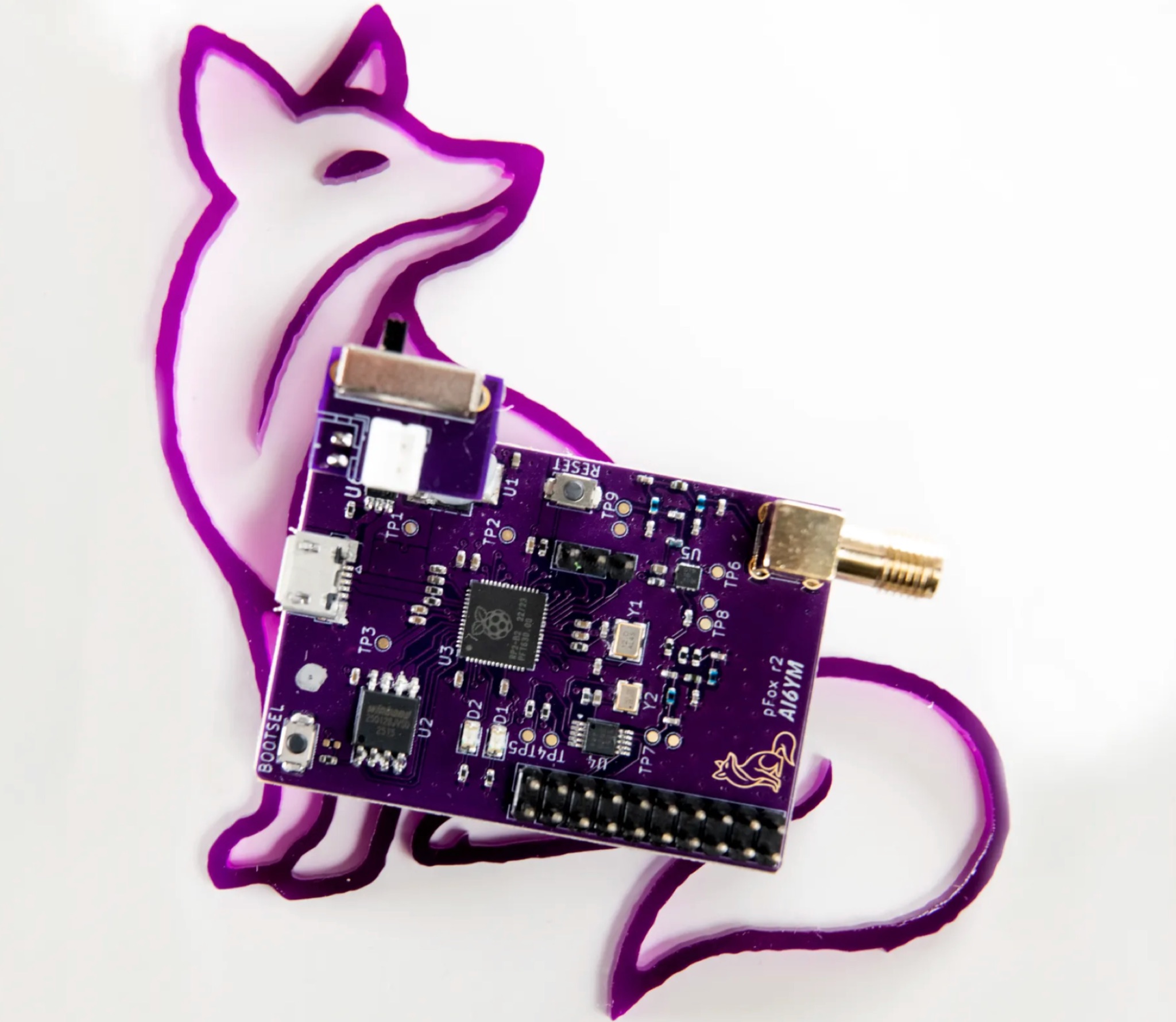 The PicoFox is a versatile fox transmitter for 2-meter ham radio operators, built around the RP2040 microcontroller. With open-source hardware and software, it can be customized to suit your needs, from APRS to other digital modes. This fully assembled transmitter comes with a rechargeable battery and antenna, ready for use. The design allows for easy addition of features like sensors or interactivity. Modulation is handled in software for smooth FM output, with ample CPU, flash, and GPIO available. Configure your PicoFox by connecting it to a computer via USB and adjusting settings in a text file. Explore the possibilities of this innovative transmitter for your amateur radio projects.
 -
 This article details the design and construction of a compact 20-meter QRP SSB transceiver by Pete Juliano, N6QW, measuring just 2 x 4 x 2 inches—small enough for a shirt pocket. Inspired by a 1963 QST design and refined from a prior version, it employs bilateral circuits, a 4.9152 MHz homebrew crystal filter, switched-crystal VXO for 60 kHz coverage (14.160-14.220 MHz), and standard components like ADE-1L mixers and IRF510 PA for 1W output. Key innovations include a double-sided PCB skeletal frame for shielding and isolation, Vectorboard sub-assemblies, and ultra-miniature relays. The bilateral receiver/transmitter shares stages, omitting AGC for simplicity, while a W3NQN LPF and optional 10W external amp enable DX contacts. Tune-up focuses on crystal matching and bias for linearity. Videos on YouTube demonstrate performance, confirming excellent stability and audio. Total cost nears $100, prioritizing portability over features like CW.
 -
 Chavdar Levkov, LZ1AQ, presents an experimental comparison of small wideband magnetic loops, building on his previous work on wideband active small magnetic loop antennas. His research focuses on increasing loop sensitivity by maximizing the short-circuit current, which is directly tied to the "loop factor" M = A/L, where A is the equivalent loop area and L is its inductance. Levkov's methodology involves reducing inductance and increasing area through parallel or coplanar crossed (CC) configurations, comparing these designs against a reference single quad loop of 1 m2 area. Experimental verification included testing three distinct loop types: a simple quad loop, two coplanar crossed (CC) loops, and eight parallel loops, all designed to have a total geometric area of 1 m2. Measurements were conducted at 1.8, 3.5, 7, and 10 MHz using a small transmitter 270 meters away, with a Perseus direct sampling receiver for precise signal level assessment. The results consistently showed that CC loops, particularly Loop 5 (two CC circular loops with 1.44 m2 total area), yielded significantly higher currents, up to 9.1 dB over the reference loop at 3.5 MHz, validating M as a reliable predictor of loop sensitivity. Numerical simulations using MMANA further corroborated the experimental findings, demonstrating an almost perfect correlation between the calculated M factor and the induced loop current for 15 different loop models. Levkov concludes that CC loops offer superior sensitivity for a given loop area, while parallel loops are advantageous for minimizing physical volume. Practical recommendations suggest using loops with an M factor greater than 0.5 uA/pT for quiet rural environments, and he provides a spreadsheet tool, WLoop_calc.xls, to aid in optimizing loop configurations for specific operational needs.
 -
 A detailed guide presents a simple 2-element quad antenna for 2m, offering ease of construction, portability, and efficient performance across the 144-148 MHz band. The design allows quick disassembly for storage and features adjustable polarization, making it ideal for various applications, including transmitter hunting and SSB operations.
 -
 Effective suppression of harmonics and parasitic radiation from HF transmitters is crucial, especially with the increasing sensitivity of VHF/UHF radio channels to interference. This project details a hybrid low-pass filter (LPF) designed to operate across the HF bands up to 51 MHz, making it suitable for 6-meter band operations while providing deep VHF/UHF suppression. The design addresses the challenge of modern interference landscapes, where even microvolt-level signals can disrupt wireless sensors and other simple VHF/UHF receivers. The filter utilizes a single elliptic link, combining high cutoff steepness with robust suppression in the hundreds of megahertz range. A key feature is the use of only two standard capacitor values, simplifying construction and component sourcing. The article provides a detailed schematic, performance characteristics, and _RFSim99_ model file, demonstrating a reflection coefficient S11 below 0.017 (VSWR < 1.03) across 1-51 MHz, ensuring minimal degradation to the antenna system. Construction notes include coil winding specifications and capacitor selection guidance, with recommendations for _FR-4_ assembly. Two capacitor sets are presented, with the first variant recommended for its lower RF current demands, keeping currents below 3 A at 1 kW passing power at 51 MHz. Fine-tuning involves adjusting frameless coils, with considerations for capacitor tolerance and high-frequency capacitance measurement accuracy.
 -
 The POCKET TUNER V1.1 is a highly compact HF T-Match antenna tuner designed for QRPp and QRP portable operations. With a credit card-sized form factor, it is tailored for low-power setups, supporting HF bands from 10m to 40m. The tuner features a unique design using rotary switches for precise capacitor adjustments, allowing tuning in small increments. Its inductance selection is optimized for various bands, ensuring efficient performance. Equipped with a resistive tuning indicator, it protects the transmitter by reducing SWR during adjustments. This versatile and portable tuner is ideal for field operations, enabling efficient antenna matching for low-power rigs.
 -
 This project presents a compact QRP SWR meter featuring a 0.96" OLED display (128x64 pixels) for high-contrast visibility, updated with software fixes for display compatibility, improved low-power performance, and support for ATtiny45/85 microprocessors. A 1.3" OLED version accommodates visibility needs. Designed for HF QRP transmitters (3-15W), it uses a Breune coupler with germanium diodes for accurate SWR measurement. Powered by a AAA battery, the meter offers a standalone solution for impedance matching, with a 3D-printed enclosure enhancing portability.
 -
 KISS703 is a 703 Hz narrowband digital mode for amateur radio, designed for simple, low-power operation without computers. A 500 Hz pilot tone ensures frequency alignment, replaced by unique tones for 37 symbols (letters, numbers, space). Built from common discrete components, it draws about 40 mA at 12 V, ideal for SOTA/IOTA use. The receiver uses amplification, wave shaping, and a pulse-counting frequency meter for manual decoding via a calibrated meter. Transmitter and receiver calibration involves marking meter positions for each tone, enabling fully self-contained messaging with minimal hardware in portable or fixed operations.
 -
 W0VLZ's Homebrew Gallery showcases vintage radio projects built with vacuum tubes, offering a fascinating look at historical transmitter and receiver designs from the 1920s-1950s. The site provides detailed descriptions, safety warnings, and links to resources. Ideal for amateur radio enthusiasts interested in classic homebrew gear and radio history.
 -
 The article discusses the construction of a UHF band-stop stub filter to protect an APRS receiver from potential damage during a balloon launch. The author, who communicates using a 441 MHz transmitter, needed to ensure that the RTL-SDR dongle receiving at 144 MHz wouldn't be damaged by the transmissions. The solution involved creating a quarter-wavelength open stub filter using coaxial cable, which attenuates the 441 MHz signal while allowing the 144 MHz signal to pass through. The filter's design is based on the principles of constructive and destructive interference, with careful measurement and trimming to achieve the desired frequency response. The final filter provided 34.8 dB of insertion loss at 441 MHz and minimal loss at 144 MHz, effectively protecting the receiver.
 -
 Twenty 1-watt carbon film resistors are configured in parallel to construct a 50-ohm **dummy load** for amateur radio applications. The design incorporates a heatsink for thermal dissipation and an **SO-239 connector** for RF input, making it suitable for QRP operations. This budget-friendly project details component selection, soldering techniques, and mounting procedures, achieving a continuous power rating of 10 watts and intermittent handling of up to 100 watts across HF and VHF frequency ranges. The resource provides a step-by-step guide for assembly. This construction offers an economical solution for essential shack tasks such as antenna tuning, transmitter testing, and SWR meter calibration without radiating an RF signal. The utilization of readily available components significantly reduces the overall build cost compared to commercial alternatives, providing radio amateurs with a functional and reliable test accessory. While specific VSWR measurements are not provided, the design prioritizes practical utility for low-power transceiver diagnostics and general RF experimentation.