Search results
Query: 20 meter
Links: 564 | Categories: 6
-
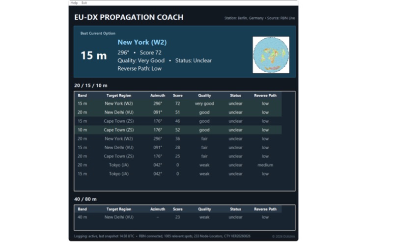 EU-DX Propagation Coach v0.9.3 processes live _Reverse Beacon Network_ (RBN) spot data, providing practical DX propagation guidance for European radio amateurs. The software offers a real-time RBN-based propagation overview, including directional guidance, enabling users to optimize band usage based on current conditions. It features five selectable European station locations and ten global DX reference centers, delivering propagation scoring for the 10, 15, and 20-meter bands, alongside a 40/80-meter overview. Dynamic azimuth and reverse-path information are calculated for each DX direction, assisting operators in precise antenna aiming. The application is distributed as a Windows ZIP archive, requiring full extraction before execution. A SHA-256 hash is provided for download integrity verification, ensuring the downloaded file matches the original. Users should note the software is provided "AS IS," and DL6UAA disclaims liability for any resulting damage or data loss. The tool is designed to run on Windows platforms, offering a dedicated utility for real-time propagation analysis.
 -
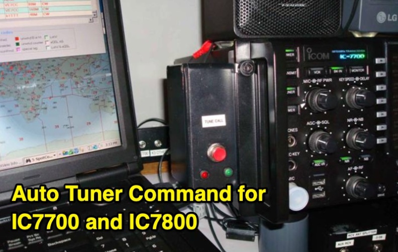 An Arduino-based interface provides a remote tuner call command for Icom **IC7700** and **IC7800** transceivers, addressing the lack of a built-in function for external tuners such as the MFJ 998RT. This setup initiates a low-power transmit signal, typically 15 watts, allowing the remote autotuner to perform its matching sequence. The article details the required CI-V line communication and modifications to existing Arduino code, specifically referencing contributions from Jean-Jacques ON7EQ for improved Icom interrogation routines. The system involves a sequence of steps: storing the transceiver's current mode and power, disabling the internal autotuner, activating a control relay to interrupt the amplifier line, switching to RTTY mode at low power, and initiating transmit. The transmit duration is manually controlled by the operator, observing the SWR meter until a low SWR is achieved, then a second button press stops the transmission. A built-in 4-second transmit limit provides a safety measure. After tuning, the routine restores the original mode and power settings, re-enables the internal autotuner, and performs a brief 2-second RTTY transmission for internal tuner adjustment. The circuit diagram includes a Panasonic form 2 relay for amp control and emphasizes critical delays in the Arduino code for stable operation at 9600 baud CI-V communication. Compatibility with logging software like DXLab, N1MM, and N3FJP is noted, with specific interrogation time settings required to avoid conflicts.
 -
 Over 200 distinct 2-meter band amateur radio repeaters are cataloged for Australia, providing essential operational data for VHF communication. Each entry specifies the repeater's output frequency, often including the input tone (e.g., **91.5 Hz** or **123.0 Hz** CTCSS) and the repeater's callsign (e.g., _VK2RSC_, _VK3RHF_). Locations are precisely noted, frequently referencing specific towns, mountains, or geographical features such as "Kinglake, Kangaroo Ground" or "Adaminaby, Mars Hill." The resource also indicates various digital modes and linking capabilities where applicable, such as "FMEchoLinkFusionWIRES-X" or "DMR," alongside standard FM operation. This detailed listing facilitates local and regional VHF communication, enabling hams to program their transceivers accurately for repeater access. The data is presented in a clear, tabular format, making it straightforward to identify repeaters by frequency and location.
 -
 The Spartan Sprint Special 40m CW Transceiver, originally documented in 2002 and reproduced in 2019, details a **QRP** direct conversion rig designed for portable operation. This project evolved from an experimental CMOS digital IC receiver, which proved too noisy for weak signals, into a dedicated 40-meter CW transceiver. The author, VE3SMA, aimed for reduced size, lower weight, and decreased receive current drain compared to earlier iterations, drawing on his extensive contesting experience and even his time operating million-watt transmitters at Radio Canada International. This compact transceiver delivers approximately 200 mW output, VFO-tunable over 15 kHz within the 40m band, and weighs a mere 73 grams (0.16 lb) including its balsa wood case. It features fast semi-break-in and sidetone, with a receive current draw of about 14 mA (no signal) and transmit current draw around 125 mA key down. The design incorporates various construction techniques, including knife-cut surface mount boards and through-hole components, often salvaged from junked cordless phones and cellphones. Despite its direct conversion architecture, which offers usable but not superheterodyne-level selectivity, the rig proved effective, achieving a fourth-place finish in a June 2001 Spartan Sprint contest when paired with a 26-foot vertical antenna. The article provides comprehensive circuit details, including an unconventional VFO using a high-speed CMOS inverter chip and a balanced mixer utilizing a 74HC4053.
 -
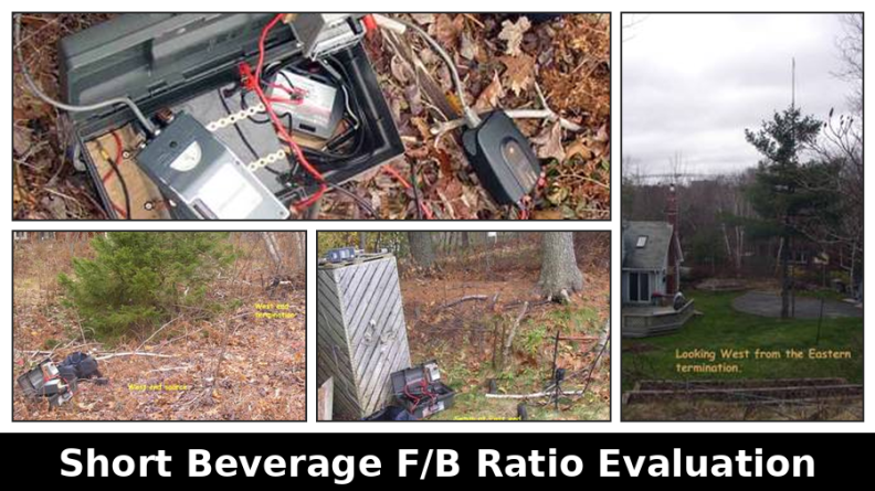 This resource presents a non-rigorous evaluation of the front-to-back (F/B) ratio of short Beverage antennas, specifically designed for low-band operation on frequencies such as 160, 80, 40, and 30 meters. The author, VE1ZAC, details the methodology used to measure the F/B ratio, which involves using a Millen Grid Dip Oscillator as a portable signal source. Measurements were taken by switching the antenna direction and recording S Meter and preamp readings to derive gain numbers. The document discusses the challenges faced in achieving accurate measurements and the assumptions made during the process, such as the calibration of S Meter units at 6 dB. This evaluation is particularly relevant for amateur radio operators interested in antenna performance on low bands.
 -
 The St Paul Island CY9C DXpedition is scheduled for August 26, September 5, 2024. All bands from 160-6 meters are planned.
 -
 The author discusses ways to display VHF and higher bands using a K3/10 as transverter, NooElec Upconverter, SDR, and SDR-Console. He observed that the results were remarkable, with the tuned frequency visible at +/-100kHz. The K3 Interface Option (KXV3A) produces a buffered IF output at 8.213MHz, which is received using a NooElec NESDR SMArt SDR dongle and Ham It UP Upconverter. The SDR-Console program is utilized, with Omnirig synchronizing the SDR and K3. To configure the system, particular parameters are required, such as adjusting the IF frequency to 133.213MHz (125MHz + IF frequency) and inverting the spectrum. The Panadapter demonstrated ES activity at 10m, and modest software tweaks may be required for improved performance.
 -
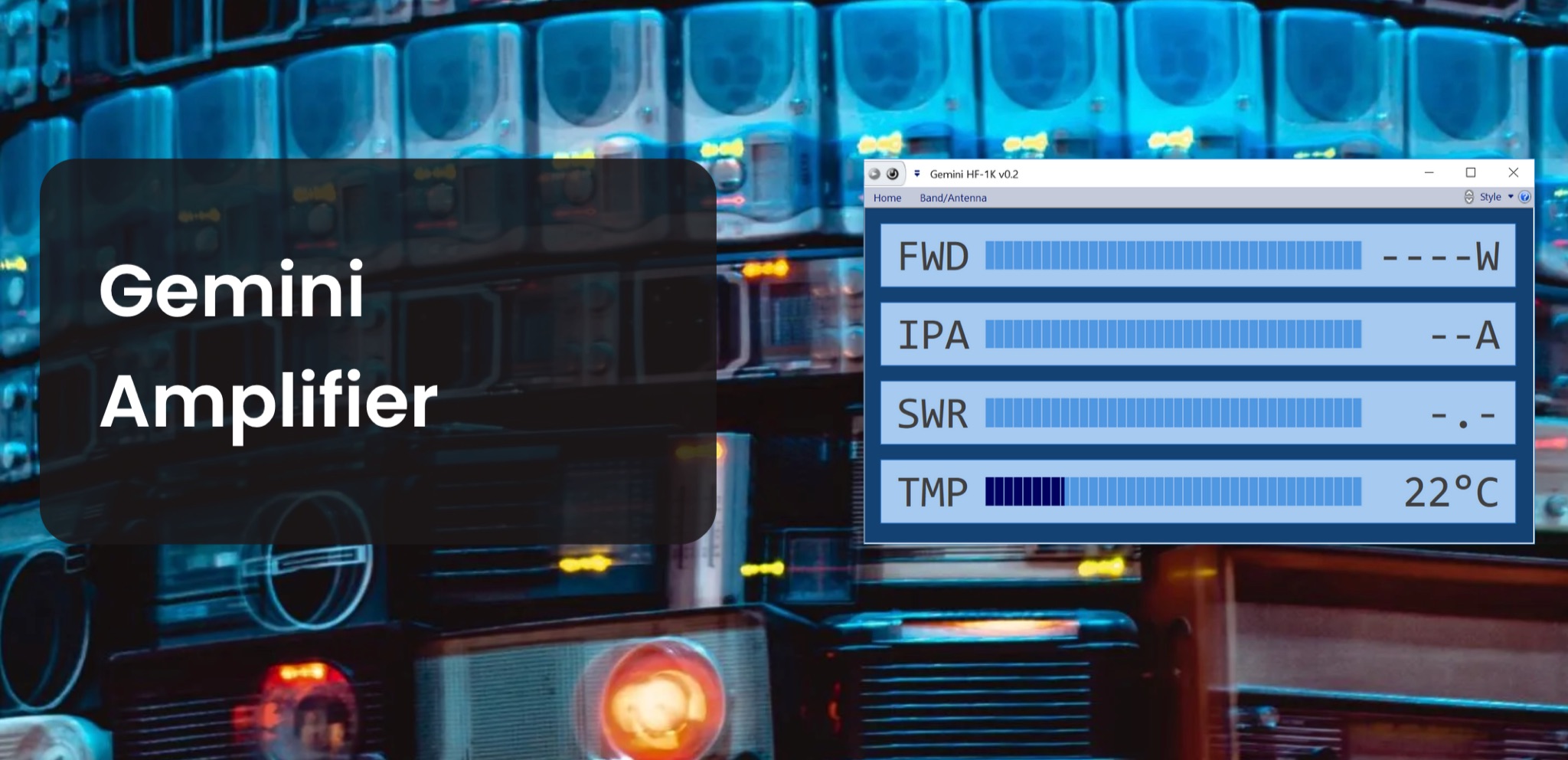 The Gemini Amplifier Remote Control software operates on Windows 7 and above, facilitating remote management of the Gemini HF-1K and DX-1200 amplifiers. Users connect via Ethernet, configuring the amplifier's IP address through the front panel. The software allows seamless band and antenna selection, saving settings for each band without requiring transmission. Integration with _OmniRig_ from Afreet Software, Inc. enables automatic band adjustments based on the radio's frequency changes. Users can configure serial or virtual serial connections, with tracking options accessible through the ribbon bar. The software supports speech functionality, enhancing accessibility for operators. Firmware updates, such as version 2.5Ee, introduce features like background datalogging and power output control, uploaded via FTP. Version 1.2.0 allows users to offload internal parameter data for support purposes. The firmware upload process requires the amplifier's IP address and port 21, taking approximately 90 seconds. Users are encouraged to upgrade to the latest firmware for improved performance and remote diagnostics.
 -
 The 4m Slim Jim antenna project provides a construction guide for a low-cost, high-performance aerial designed specifically for the 70 MHz FM band. This design achieves a 1:1 SWR across the 4m FM band with straightforward adjustment of the feed point, utilizing RG-58 coax. Its low angle of radiation contributes to effective signal propagation. Construction involves using plastic knitting needles as spreaders and a telescopic fishing pole for support, with components secured using two-part epoxy. Annealed bare single-core copper wire forms the radiating element. The setup process includes raising the antenna at least 3 meters above ground for tuning, adjusting the RG-58 feed point for optimal SWR, and then soldering connections. Waterproofing is achieved with yacht varnish. The design emphasizes low wind resistance for durability, making it suitable for exposed outdoor installations. A PDF construction diagram is available to supplement the written instructions.
 -
 The Alfa Alfa (AA) DX Group, established on March 1, 1974, in the Netherlands, is presented as the pioneering Dutch 27mc DX group. It details the group's historical significance, particularly its revolutionary use of the '000' club callsign (19AA000) which influenced international 11-meter group callsign structures. The resource outlines the group's re-establishment in 2024, inviting new active CB operators and _Short Wave Listeners_ (SWL) to join its ranks, emphasizing a free worldwide membership model. Membership requirements are specified, focusing on active participation with an assigned AA callsign. The group provides QSL card management services, with options for direct QSL requests requiring **3 USD** and a Self-Addressed Envelope, or **4 USD** via PayPal for expenses. It also mentions upcoming initiatives like an _AA DX Contest_ and an award program, with sections for certificates and plaques currently under construction. The site also lists useful CB resources, including an 11M DX Cluster and an 11M Callsign Database, and provides contact information for the founder, 19AA001 Mr. Theo, and the Worldwide QSL Manager, 178AA001 Mr. Emil, based in Bulgaria.
 -
 This page discusses the construction and use of a low pass filter for MF/LF reception, specifically for the 630 meter and 2200 meter bands. The author, KA7OEI, shares technical insights and practical advice related to amateur radio, with a focus on improving reception in the low-frequency bands. This resource is useful for hams interested in building their own filters to enhance their MF/LF reception capabilities.
 -
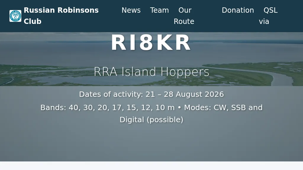 Presents the RI8KR RRA Island Hoppers DXpedition, detailing its schedule from August 21 to 28, 2026, and its objective to activate four new island groups in the Ob Bay of the Kara Sea. The expedition targets specific Russian River Club (RRC) references: RR-06-66 (Ob River Delta Islands West), RR-06-67 (Ob River Delta Islands North-West), RR-06-68 (Ob River Delta Islands North), and RR-06-69 (Ob River Delta Islands Center/North). Operators Vladimir, RK8A, and Igor, UA3EDQ, will operate on 40, 30, 20, 17, 15, 12, and 10-meter bands using CW, SSB, and potentially Digital modes. Three of these activations contribute to IOTA AS-109, an entity not activated since 2013. The page provides QSL information via RZ3EC (Eugene Shelkanovtsev, P.O. Box 70, Orel 302028) and online platforms including RRAWARD.RU, LoTW, RDAWARD.RU, and CFMRDA.RU. It lists supporters of the expedition, acknowledging contributions from various amateur radio operators. Recent updates confirm the purchase of airplane and boat tickets for the team's travel to Salekhard and Salemal/Panayevsk, indicating active preparation for the August 2026 operation.
 -
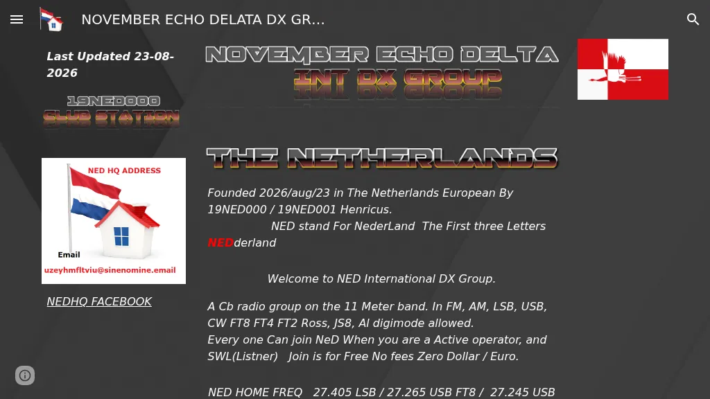 Presents the NED International DX Group, a **CB radio** organization established in the Netherlands on August 23, 2026, by 19NED000 and 19NED001 Henricus. The group primarily operates on the **11-meter band**, utilizing various modes including FM, AM, LSB, USB, CW, FT8, FT4, FT2 Ross, and JS8, with all digital modes permitted. Membership is free and open to active operators and SWLs. Key operating frequencies include 27.405 LSB, 27.265 USB for FT8, and 27.245 USB for JS8. The group also maintains activity on PMR Channel 10 at 446.11875 MHz FM. The organization is actively seeking volunteers for roles such as webmaster (proficient in PHP, MySQL, and security), digital eQSL and paper QSL card management, logo and banner design, and country/province directors.
 -
 The H49A DXpedition to the Solomon Islands (OC-047, IOTA OC-047) is scheduled for a 13-day operational period, commencing on October 9th and concluding on October 21st, 2026. This **DXpedition** will feature a six-member team, including Rolando (9A3MR) as Team Leader, Zrinko (DK8ZZ/YT3ZZ), Mladen (9A2NA), Frane (9A3CJY), Kristijan (9A4WY), and Livio (9A7Y). Operations are planned across all **HF bands** and 6 meters, utilizing CW, SSB, and FT8 modes. This activity provides a significant opportunity for radio amateurs worldwide to log the Solomon Islands, a sought-after DXCC entity. The team aims to maximize contacts across various bands and modes, contributing to global DXCC and IOTA awards. Specific QSL routes and logistical details are anticipated to be published closer to the operational dates.