Search results
Query: wave
Links: 988 | Categories: 55
Categories
- Antennas > End-Fed > End Fed Half Wave Antenna
- Operating Modes > Longwave
- Antennas > Longwave
- Manufacturers > Microwave
- Shopping and Services > Microwave
- Operating Modes > Microwave
- Antennas > Microwave
- Shopping and Services > Antennas > Microwave Antenna
- Manufacturers > Antennas > VHF UHF Microwave > Microwave antennas
- Technical Reference > Mircrowave
- Software > Shortwave
- Antennas > Shortwave
- Shortwave Radio
- Manufacturers > Antennas > VHF UHF Microwave
- Technical Reference > Standing Wave Ratio
- DX Resources > Beacons > 10 GHz Beacons
- Antennas > 40M > 40 meter Loop Antennas
- Operating Modes > Aircraft scatter
- Manufacturers > Antennas
- Radio Scanning > Regional > Australia
- Shortwave Radio > BCL Resources
- DX Resources > Beacons
- Shortwave Radio > Beginner's guides
- Shortwave Radio > Broadcasters
- Manufacturers > Broadcasting Equipment
- Shortwave Radio > Clubs
- Manufacturers > Antennas > VHF UHF Microwave > Discone Antennas
- Antennas > End-Fed
- Manufacturers > Antennas > VHF UHF Microwave > Ground Plane Antennas
- Antennas > Horn
-
 Welcome to our line of Low Frequency, Natural Radio Research, Broadcast, Marine and Shortwave products. Our evolving product line is the result of our dedicated research efforts primarily in the areas of LF, VLF, MF, and HF.
 -
 Longwave refers to all frequencies below the lower end of the AM broadcasting band at 540 kHz
 -
 Meet The Breakers is a unique exploration of the CB radio culture in the United Kingdom, hosted by Colin The Head. This series delves into the lives of various CB radio enthusiasts, showcasing their setups, stories, and the vibrant community surrounding this hobby. Each episode features interviews with notable figures in the CB world, providing insights into their experiences and the equipment they use. The program not only highlights the technical aspects of CB radio, such as antennas and signal checks, but also captures the personal stories that make this hobby special. From collectors of rare equipment to modern-day users navigating the airwaves, Meet The Breakers offers a comprehensive look at the diverse personalities that contribute to the CB radio landscape in the UK. Whether you're a seasoned operator or new to the scene, this series is a valuable resource for anyone interested in the world of CB radio.
 -
 Low-frequency (LF) radio time signals, operating primarily in the 40–80 kHz range, are broadcast by national physics laboratories for precise clock synchronization. Transmitters like **JJY** (40 kHz, 50 kW; 60 kHz, 50 kW), RTZ (50 kHz, 10 kW ERP), MSF (60 kHz, 15 kW ERP), WWVB (60 kHz, 50 kW ERP), RBU (66.66 kHz, 10 kW), and DCF77 (77.5 kHz, 50 kW) cover vast geographic areas, often several hundred to thousands of kilometers. LF signals offer distinct propagation advantages over higher-band transmissions such as GPS. Their long wavelengths (3–6 km) enable effective diffraction around obstacles like mountains and buildings. The ionosphere and ground act as a waveguide, eliminating the need for line-of-sight and allowing a single powerful station to cover extensive regions. Ground wave propagation minimizes ionospheric variability effects on transmission delay, and signals penetrate most building walls effectively. Robust and low-cost receivers, often priced at 20–30 USD/EUR, are widely used in radio clocks. These receivers typically comprise a tuned ferrite core antenna, a receiver IC (e.g., Atmel T4227, U4223B, MAS1016) for amplification and AM detection, and a microcontroller for decoding the time signal and phase-locking a local clock. Specific components for DCF77, MSF, and WWVB are readily available from vendors like HKW Elektronik and Ultralink.
 -
 G3PHO website dedicated to the microwaves operations
 -
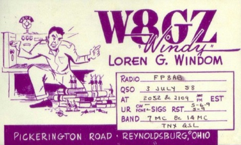 The Windom antenna, one of the oldest antennas developed for amateur use, has had a complicated history, one as interesting as the theory of the antenna itself.
 -
 A web site maitained by KK6MK about microwave and related technical material
 -
 A blog dedicated to military communications shortwave intercepts, sponsored by the Teak Publishing
 -
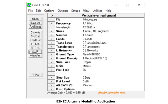 This project is a full wavelength, horizontal, loop antenna for the 40 metre Amateur Radio band, built using insulated copper wire in a diamond shape, supported by egg insulators, tethered to 4 masts, each 6.5m high
 -
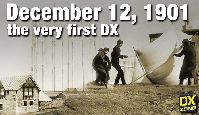 On December 12, 1901, Guglielmo Marconi successfully received the first transatlantic wireless communication, a Morse code "S" (three dots), at 04:30 GMT. This article details the setup for this groundbreaking experiment, noting Marconi's receiver in St. John’s, Newfoundland, Canada, utilized a _coherer_ and an antenna elevated by balloons and kites. The transmitting station at Poldhu, Cornwall, England, featured twenty-four 200-foot ships' masts and a 25-kilowatt alternator. The resource explains how this contact disproved contemporary beliefs about radio wave limitations due to Earth's curvature, later understood through _ionospheric propagation_. It frames Marconi's achievement as the "very first DX" in amateur radio terms, defining DX as telegraphic shorthand for distance and _DXing_ as the hobby of receiving distant signals. The article also provides external links for further reading on Marconi's experiments and the science behind transatlantic radio signal reception.
 -
 NJ2X is a licensed amateur radio operator (FCC Amateur Extra) who enjoys casting electromagnetic waves into the ether. NJ2X pursues many aspects of the hobby including chasing DX, participating in mini-DX expeditions, building equipment and antennas, and papering his shack walls with ARRL awards. NJ2X dedicates this amateur radio oriented site to helping others who also enjoy the greatest of scientific hobbies. The site is suitable for all readers - families, the young, and the young at heart.
 -
 Replica of David Sarnoff\'s Key, Marconi operator at Station WHI
 -
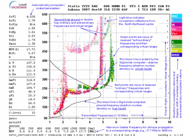 This page displays the current ionogram and tries to determine the nearest digisonde report to your location. Data coming from this sondes are used to determine the MUF for oblique propagation on HF spectrum
 -
 Established in 1954, RAIBC is a national society and Charity, dedicated to supporting Radio Amateurs and Short-wave Listeners with disabilities. The RAIBC logo is recognised throughout the amateur radio world.
 -
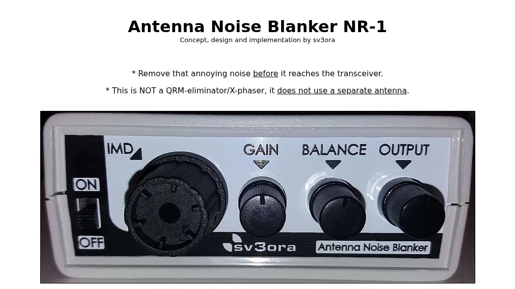 Mitigating impulse-type noise, a common challenge in the **HF radio spectrum**, often requires specialized processing before the signal reaches the transceiver's receiver stages. The NR-1 addresses this by functioning as an RF interference removal device, specifically a noise blanker, targeting transient noise sources. Its operational range extends from 1.6 MHz to beyond 70 MHz, making it suitable for various amateur radio bands and general shortwave listening applications. Unlike QRM eliminators or X-phasers, the NR-1 does not require a separate noise antenna for its operation, simplifying its integration into existing station setups. The device's design focuses on wideband performance, allowing its use both within and outside the allocated amateur radio frequencies. Documentation detailing its operation is available, providing insights into its technical specifications and deployment. This unit is a hardware product, conceptualized and implemented by SV3ORA.
 -
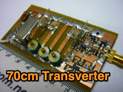 The project in this article illustrates how to do this in a simple and low cost way so that you can easily access the microwave bands using the existing HF or HF/VHF transceiver as IF.
 -
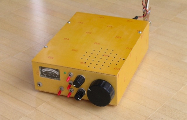 Homemade receiver for 80 meters band. The receiver works very well (in fact better than some of its successors), especially the AGC makes listening to 80m QSOs a real pleasure. Sensitivity is not cutting-edge, but on a full-size short-wave antenna it is by fare sensitive enough.
 -
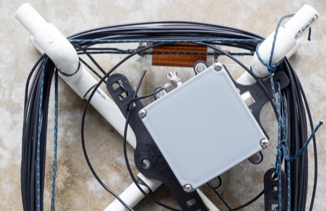 An interesting article on end fed half-wave wire antennas with a couple of original experiments. Author illustrate the role of the QRP matchbox, and a 40/20 meter antenna with a center stub making it a large bandwidth antenna for 40 and 20. Includes also an 80/40 end fed with the typical coil to make it available on 80 merts band.
 -
 Sponsors of WAVE, WACAN awards
 -
 Number stations are shortwave transmissions from foreign intelligence agencies to spies in the field of foreign countries.
 -
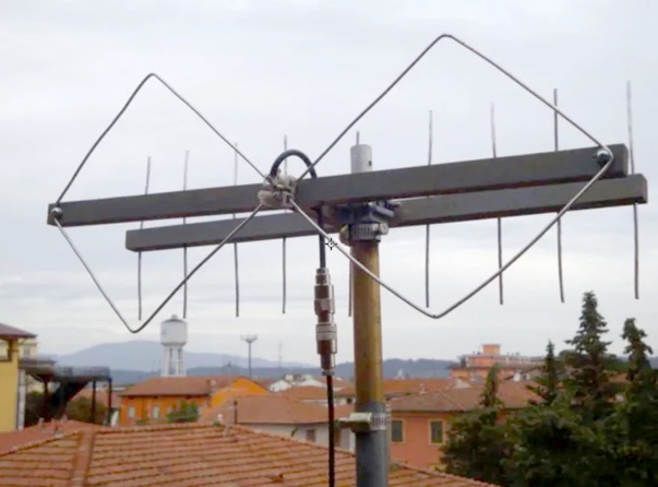 The structure of this dual band VHF UHF antenna is very simple. It consists of two identical square loops, whose sides measure a quarter wave, connected together at the ends. A project by I5NZR
 -
 Two beacons in 3 and 1.2 cm band, 10368.755 MHz and 24048.870 MHz
 -
 This page delves into the Inverted V antenna, a source of myths among ham radio operators. The author explores the behavior of this antenna type with a focus on a 20m half-wave dipole positioned 10m above the ground. From Pythagoras to high school math, the article simplifies the calculation of dimensions and angles for setting up an Inverted V antenna. It includes a spreadsheet for calculating hypotenuse length and angles, crucial for antenna setup. Additionally, it provides insight into the radiation pattern of a 'flat' half-wave dipole at 10m height. Useful for hams planning to optimize their antenna setup. In Norwegian.
 -
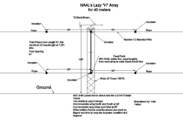 Make them simple then Make them work. The LAZY H antenna is a general type of antenna that is in the curtain array family. By placing two 1 wavelength dipoles in a plane that is at right angles to the direction of maximum radiation and keeping the proper in-phase current condition to each element, you can achieve a high gain bi-directional antenna.
 -
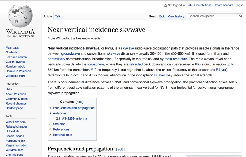 The wikipedia article about NVIS Near vertical incidence skywave with information about usable frequencies and some general information on main NVIS oeprations usages
 -
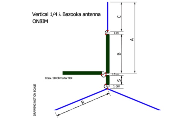 A quarter wave vertical omni-directional antenna for 7 MHz. Formulas for dimensions in feet and meters are provided. Ideal radial angle is between 35° and 45°. Velocity factor (Vf) varies based on coax type.
 -
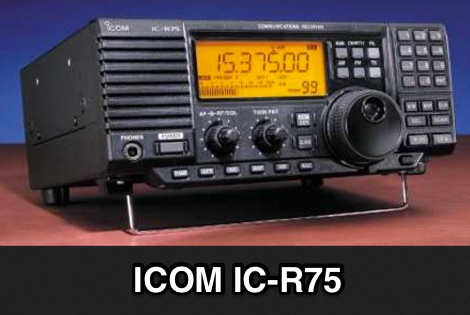 A detailed review of the Icom IC-R75 30 kHz -6 0 MHz Receiver first introduced in 1999
 -
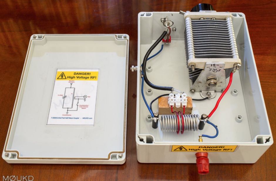 A home made end-fed half-wave antenna coupler with antenna lenght calculator and counterpoise calculator based on center frequency. Includes pictures and drawings along to antenna homebrewing instructions with a home made on air wound transformer
 -
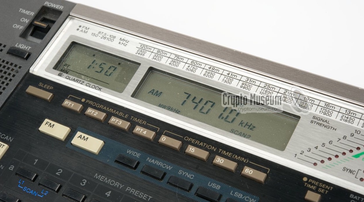 A numbers station, also known as a one-way voice link (OWVL), is a special type of unusual radio broadcast, generally on the Short Wave (SW) radio bands
 -
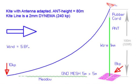 An essential kite antenna plan for the top band, Antenna has been tested at half wave and quarter wave.
 -
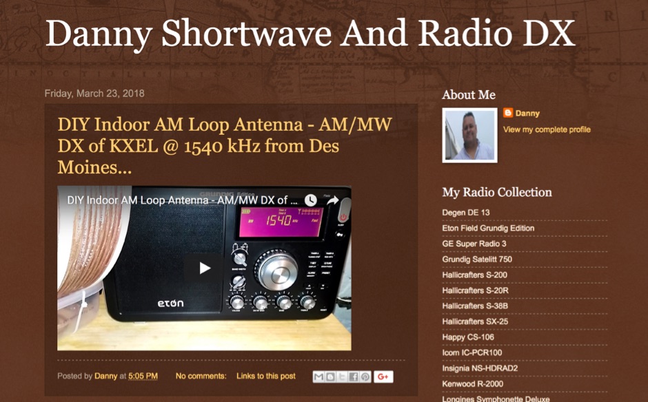 This channel is all about radio listening and dxing. I will be covering frequency bands like longwave, AM/MW and shortwave. I'm embarking on my renew interest in this hobby since my childhood.
 -
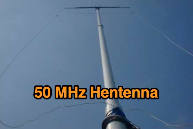 An Hentenna project for the six meters band. The standard size of standard hentenna is width 1/6 wavelength x height 1/2. The antenna build in this project is a full wavelenght antenna for the 50 MHz providing a 6.8 dbi gain.
 -
 Stanley Grixti - 9H1LO is I.A.R.U. Microwave Manager and Vice-Secretary for M.A.R.L
 -
 Equipment and Components for the RF and Microwave industry. AtlanTecRF is a global supplier of microwave and RF components and equipment to the aerospace, defence, telecommunications and scientific markets.
 -
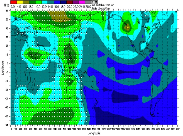 This paper presents the method of calculating the maximum usable frequency (MUF) and field strength of radio waves reflecting 2 times at the F2 ionosphere layer under inhomogeneous conditions of the ionosphere. The comparison between predicted and measured MUF has shown that the proposed method significantly increases the accuracy of calculation MUF.
 -
 Fix VHF TVI problems usign a quarter wave stub filter
 -
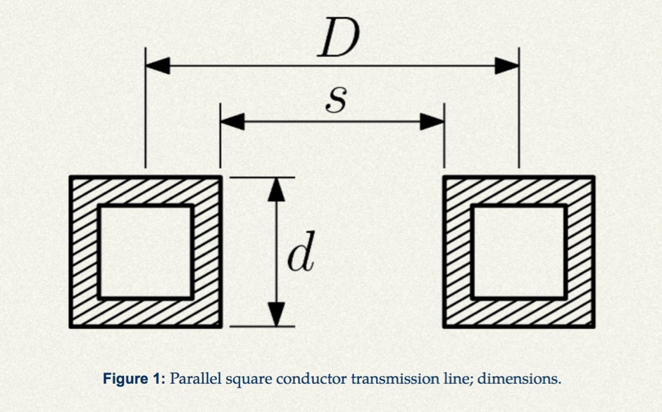 Design a parallel square stock balanced transmission line with this calculator.
 -
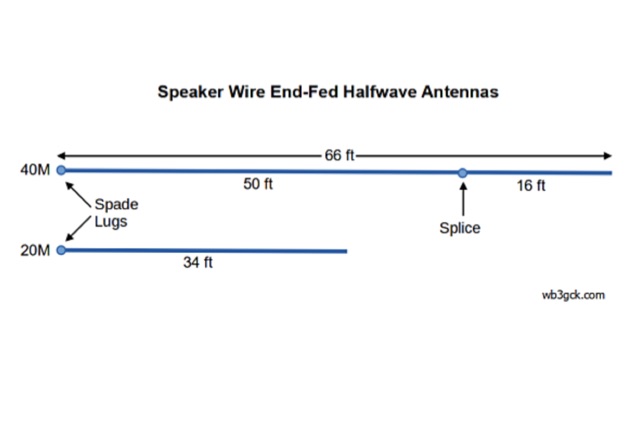 Author experiments end fed half wave antennas using common two conductore speaker wire, this article features a couple of end-fed halfwave wires for the 40M and 20M bands.
 -
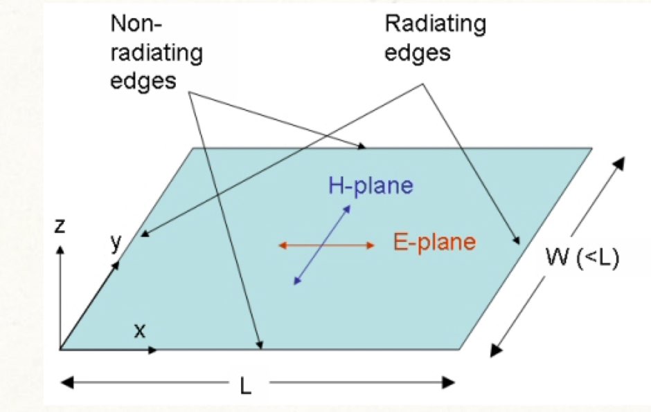 Article about the microstrip patch antennas, and in particular the rectangular, single-polarization microstrip antennas, commonly abbreviated MSA.
 -
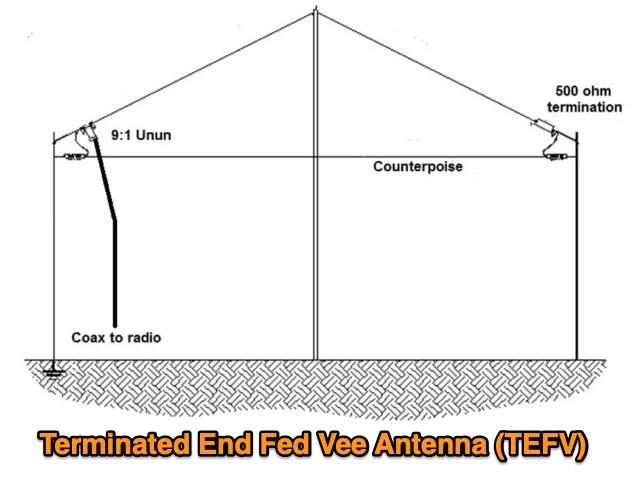 The Terminated End Fed Vee Antenna (TEFV) is a travelling wave antenna with constant current distribution. Unlike traditional resonant antennas, TEFV operates without standing waves, using a terminating resistor for broadband efficiency. With a combination of vertical and horizontal polarization, it offers wide bandwidth from 1.8 MHz to 30 MHz, eliminating the need for a tuner. Key components include a 9:1 unun transformer and a 500-ohm terminating resistor. Grounding and counterpoise enhance performance, and it can handle power losses of up to 30%. TEFV provides an effective, versatile antenna solution for amateur radio and broadcast applications.
 -
 High Speed Multimedia (HSMM) radio, as introduced by John Champa, K8OCL, represents a significant advancement in amateur radio's digital capabilities, moving beyond traditional keyboard modes like packet radio. This initiative, driven by ARRL's Technology Task Force, focuses on developing high-speed digital radio networks capable of up to 20 megabits per second. HSMM primarily facilitates digital voice (DV) and digital video (ADV), enabling real-time video transmission from emergency scenes to an EOC without expensive ATV gear, often requiring only a laptop, a PCMCIA card, a digital camera, and a small antenna. The working group's initial efforts concentrate on cultivating microwave skills within the amateur community to build and support portable and fixed high-speed radio-based local networking, or **RLANs**. These networks prove invaluable for RACES and ARES organizations, as well as homeland security and other emergency communications. Field Day exercises and simulated emergency tests (SETs) are encouraged to hone skills in rapid site surveys and deploying broadband HSMM microwave radio networks, with examples like linking Field Day logging stations or antenna test results at the Midwest VHF-UHF Society Picnic 2003. Getting started with HSMM often involves adapting off-the-shelf **IEEE 802.11** (WiFi) equipment to comply with amateur radio regulations, typically operating in the 2.4 GHz ISM bands. While consumer WiFi gear has range limitations under Part 15 rules, proper setup under amateur regulations can extend coverage significantly, with test networks like the Hinternet achieving 5-15 mile ranges at 54 M bit/s using small mast-mounted dish antennas. Careful selection of equipment with external antenna ports, high transmit power, and low receive sensitivity is crucial, along with using low-loss coaxial cable like LMR-400 for optimal performance at these frequencies.
 -
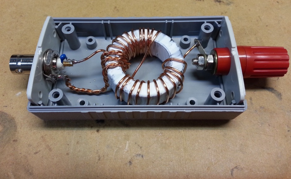 An end-fed half wave antenna matching unit made of 3:24 turns ratio on a FT140-43 toroid with a 150pF capacitor across the input.
 -
 Voldatech, a manufacturer based in China, produces a range of RF feeder cables and site components essential for amateur radio installations and telecommunication infrastructure. Their product line includes various types of coaxial cables, such as **50 Ohm** and 75 Ohm options, along with a comprehensive selection of connectors like N-type, UHF, and BNC. These components are critical for maintaining signal integrity and minimizing loss in antenna systems, whether for a home shack or a remote DXpedition setup. The company's focus on _RF Coax cables_ and connectors directly supports the needs of radio amateurs seeking reliable transmission lines for their transceivers and antennas. Amateurs often compare Voldatech's offerings to established brands, evaluating factors such as impedance matching, shielding effectiveness, and durability under various environmental conditions. The availability of diverse cable types allows operators to select optimal solutions for different frequency bands and power levels, from QRP to high-power amplifier setups. Their products are particularly relevant for those constructing new antenna arrays or upgrading existing feedline systems, aiming to achieve maximum power transfer and reduce standing wave ratio (SWR) for efficient signal propagation.
 -
 DF0WD/DL4YHF's Longwave Overview details amateur radio operations on the 135.7 to 137.8 kHz segment in Germany. The author outlines the "inofficial" European band plan, specifying segments for QRSS, TX tests, beacons, conventional CW, and data modes. Early LF activities at DF0WD began with a 20-watt CW transmitter, later upgraded to a homemade linear transverter capable of 100 watts, driven by an Icom IC706 on 10.137 MHz. The station's antenna system includes a 200-meter wire, approximately 10 meters above ground, supported by football field light-masts. Despite its length, the antenna's efficiency is noted as very low due to the immense wavelength of about 2.2 km. The author's experience highlights the significant challenge of achieving effective radiated power (EIRP) on LF, estimating DF0WD's EIRP at around 80 milliwatts based on field strength measurements from PA0SE. DF0WD/DL4YHF has successfully worked numerous countries on 136 kHz CW, including DL, F, G, GI, GM, GU, GW, HB9, HB0, LX, OE, OH, OK, OM, ON, OZ, PA, and SM. The author also mentions ongoing efforts to log contacts with CT, EI, LA/LG, and to complete a two-way QSO with Italy, demonstrating persistent activity on this challenging band.
 -
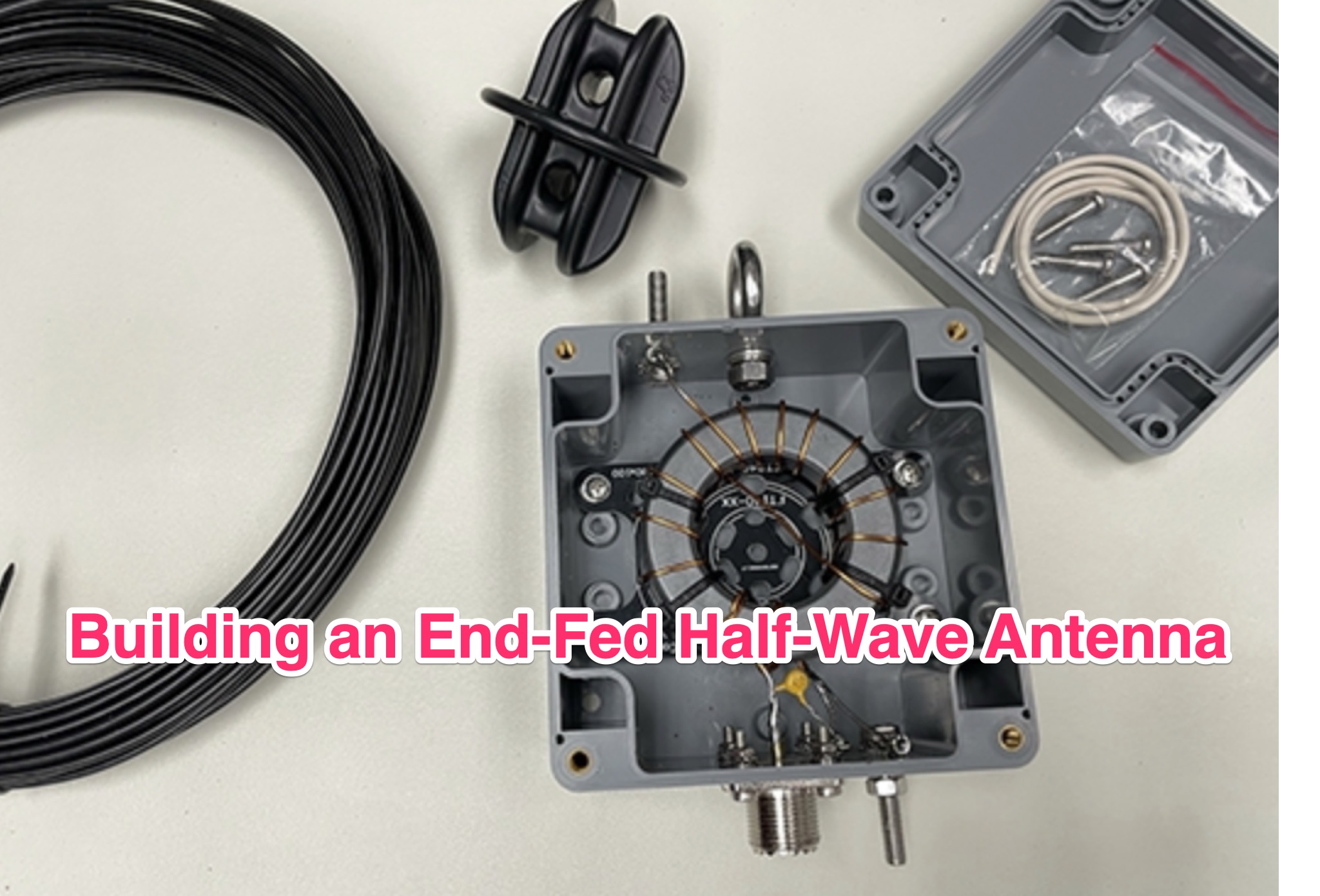 The ARRL's End-Fed Half-Wave (EFHW) Antenna Kit is an easy-to-build four-band antenna designed for 10, 15, 20, and 40 meters. Ideal for portable operations, it includes a 49:1 impedance transformer for compatibility with most transceivers. This project, detailed with step-by-step assembly instructions, involves creating a weatherproof enclosure and impedance matching network. The kit simplifies HF operations and supports multiple configurations, making it a versatile tool for amateur radio opertors.
 -
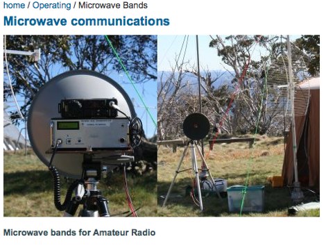 Introduction to operating on microwave bands at VKFAQ
 -
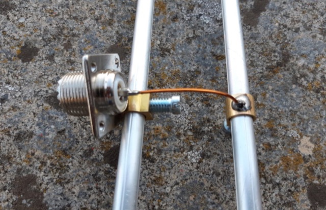 This is a simple half wave antenna for 70 cm band, made using the jpole design.
 -
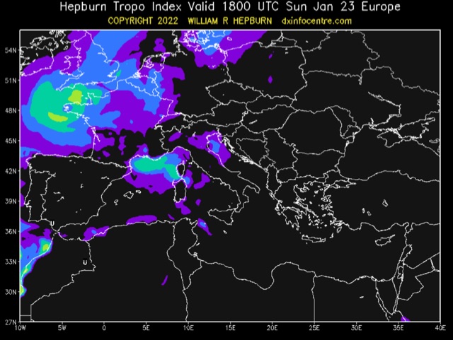 The areas noted in the forecast have the necessary atmospheric conditions to produce tropospheric bending of VHF, UHF and/or microwave radio waves. Tropospheric bending extends the range of radio & TV stations well beyond their normal limit and thus increases interference amongst stations as well.
 -
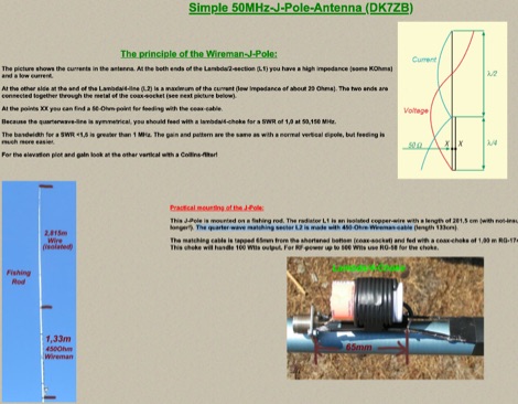 This J-Pole is mounted on a fishing rod. The radiator L1 is an isolated copper-wire with a length of 281,5 cm while the quarter-wave matching sector L2 is made with 450-Ohm-Wireman-cable
 -
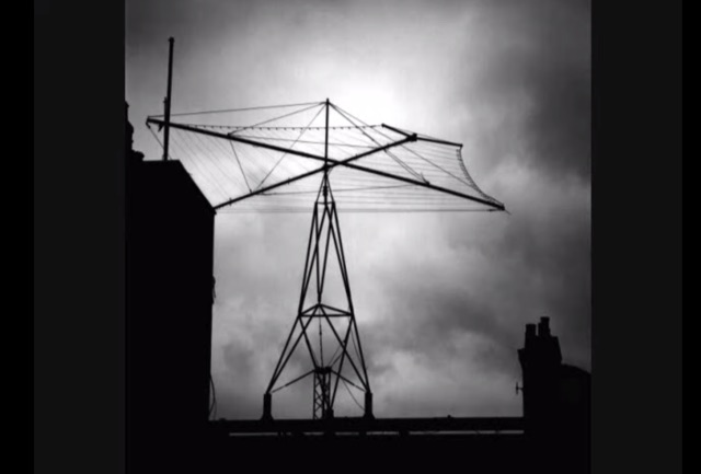 Encrypted messages, fancy technology, spies use them all to communicate, but sometimes the best way to hide is in plain sight. Right now, broadcasting across the airwaves around the world, are automated, anonymous shortwave AM radio stations that most governments won't acknowledge even exist, much less explain