Search results
Query: meter band
Links: 901 | Categories: 22
Categories
- DX Resources > Beacons > 10 meter beacons
- Antennas > 20M > 20 meter Dipole Antennas
- Antennas > 20M > 20 meter Vertical Antennas
- Antennas > 20M > 20 meter Yagi antennas
- Antennas > 40M > 40 meter Dipole Antennas
- Antennas > 40M > 40 meter Loop Antennas
- Antennas > 6M > 6 meter J-Pole Antenna
- Operating Modes > Top Band
- Antennas > 40M > 40 meter Yagi Antennas
- Antennas > 6M > 6 meter Moxon Antennas
- Antennas > 10M
- Antennas > 17M
- Antennas > 20M
- Antennas > 2M
- Antennas > 30M
- Antennas > 60M
- Operating Modes > 70 MHz
- Antennas > 80M
- Radio Equipment > HF Vertical Antenna > Cushcraft R8
- Antennas > Halo
- Radio Equipment > HF YAGI Antennas > Hy-Gain TH3JR
- Antennas > Morgain
-
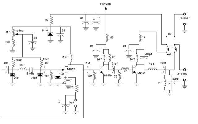 1-watt 17-meter cw transmitter that was originally done about 10 years ago as a club project for RAMS, the Radio Amateur Megacycle Society. It uses a VXO, rather novel at the time. It also uses a bandpass filter at the output rather than the usual lowpass
 -
 WB8LZR details the construction and initial field results of a multi-band vertical wire antenna, designed to complement his existing horizontal loop for improved DX on 80 meters. The antenna utilizes a 67-foot vertical wire, configured as a quarter-wave radiator on 80m, and employs a 1:1 current balun for RF isolation on 80m, 30m, and 17m. For bands like 40m, 20m, and 10m, where the wire acts as a half-wave or full-wave radiator, an additional impedance transforming _unun_ is integrated to manage the significantly higher feedpoint impedance and voltage. The author notes the vertical's performance as a receiving antenna, observing reduced noise compared to his main horizontal loop, particularly on 80m, and even hearing some long-path signals the loop missed. Initial QRP contacts, including a **1-watt** QSO with a _VP2 station_ on 30m, demonstrate its transmit capability. While the radial system is currently rudimentary, the project outlines practical considerations for multi-band vertical deployment and impedance matching.
 -
 A 14.12 dBi gain three elements cubical quad antenna for the six meters band. This Quad Antenna design page include a MMA model available to download and dimensions for each element.
 -
 Constructing a 5-element quad antenna, the author aimed for low cost and simplicity, resulting in an effective design with 11 dBi gain and SWR of 2:1 or better across the 2-meter band. Using wood and dowels, the antenna costs under $8 and takes less than two hours to build with basic tools. The model predicts excellent performance, confirmed by ARRL Lab measurements. Practical field results demonstrate improved communication, even in simplex mode.
 -
 A rotatable 40-meter dipole antenna designed and constructed to fit within backyard constraints. The project utilized two fishing poles attached to a fiberglass center pole, resulting in an easy-to-build, lightweight, and cost-effective antenna. Essential materials included fishing rods, a center support pole, mast support, and basic tools. Linear loading was implemented to achieve the necessary length for optimal performance. The antenna, which proved effective during the contest, is ideal for field days and additional contest bands. Assembly and installation were straightforward, showcasing the antenna's practicality and efficiency.
 -
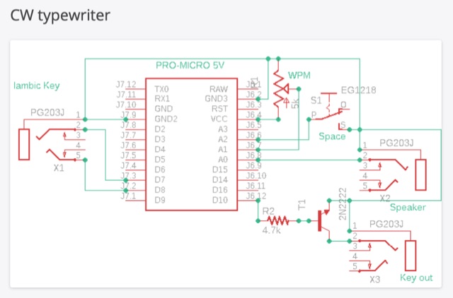 The CW typewriter is a compact adapter board that transforms Morse code into ASCII characters using an Iambic key. It connects to a computer via USB, emulating the keyboard. The device features inputs for Iambic keying and a WPM speed potentiometer, and outputs for a key and a speaker for side tone. The device can be used with various software and online typing games for practice, offering a unique and interactive way to learn and use Morse code.
 -
 This document provides a detailed guide on constructing and mounting a folded dipol for the 146 MHz frequency in a vertical configuration to be used in Yagi antennas. The step-by-step instructions and diagrams included make it easy for hams to build and set up this type of antenna. Understanding and implementing this design can enhance the performance of radio communication for Amateurs operating in the 2-meter band. Whether you are looking to improve your signal strength or experiment with antenna designs, this resource offers valuable insights and practical information.
 -
 When building antennas for the Wifi band (Like the 8dBi omni), a need for an easy way to check the antennas arose. A Voltage Standing Wave Ratio (VSWR) meter useable at the 2.4GHz band is however, hard to find.
 -
 A CW contest running every Monday, from 1630 UTC to 1729 UTC on 40 and 80 meters band
 -
 Documents the A35EU DXpedition to Tonga, specifically targeting the _IOTA OC-049_ Tongatapu group during 2018. The resource outlines the operational bands from 10 to 160 meters and the primary modes utilized, including _CW_, _SSB_, RTTY, and FT8. It provides essential information for DXers interested in confirming contacts with this rare entity, detailing the logistical aspects of the operation and the specific island group activated. This page serves as an archive for the A35EU operation, offering QSL update information and confirming that all log queries were processed and a fresh log uploaded to _Clublog_. Such details are crucial for operators seeking to verify their contacts and apply for awards like DXCC or IOTA, providing a definitive record of the expedition's activity and post-operation administrative status.
 -
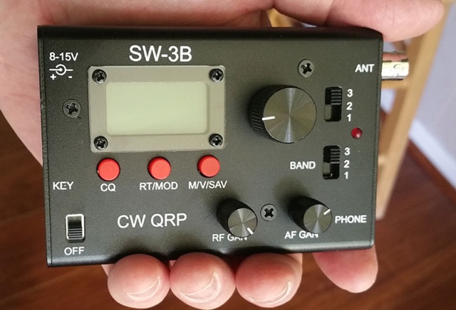 The SW-3B is a Three-band CW QRP transceiver, Weight 180g, output power 5W at 12v, 2W at 9v, works on 40 30 and 20 meters band
 -
 A homemade quarter wave ground plane anntenna for 4 meters band.
 -
 Listen to HF communications via the KiwiSDR online receiver located in Badgad IRAQ locator LM23fh. This web receiver is running a MLA 30+ antenna and can be tuned easily on all HF bands from 10 to 80 meters.
 -
 Discover the best low band receive antennas for hams with limited space. Learn about the K9AY loop antenna and Shared Apex Loop Array, two alternatives to the traditional Beverage antenna. Understand the concept of Relative Directivity Factor (RDF) and compare the performance of different receive antennas. See how the Shared Apex Loop, patented by Mark Bauman (KB7GF), offers an RDF between 8 and 10dB. Find out how to optimize antenna performance and enhance your receive capabilities on 160, 80, and 40 meters. Explore the world of low band receive antennas with insights from WB5NHL Ham Radio.
 -
 The quarter-wave Marconi working against ground is a popular and inexpensive antenna for 160 meters. A lot of newcomers to the band favor this simple antenna because it's easy to put up, it isn't too big, and it works.
 -
 The resource details active HF radio networks maintained by foreign ministries for diplomatic communications, specifically listing operational schedules and frequencies. It currently covers networks for Bulgaria, Czechia, Egypt, North Korea, Russia, Tunisia, and the United States. The content provides specific operational parameters for these government-run shortwave stations. Information includes details on _legacy modes_ of operation and specific transmission times. The site also includes schedules for various _number stations_ which often utilize similar HF spectrum allocations. The data presented aids in identifying and monitoring these unique, non-amateur radio signals across the shortwave bands. Specific sections are dedicated to the networks of North Korea and the United States, offering granular data for each.
 -
 DX Pedition to Galapagos will be active from October 26th to November 7th, from 6 to 160 meters (including Warc bands) on CW, SSB and Digi modes with at least 4 stations on the air at the same time.
 -
 The article details the design and construction of a four-band Moxon beam by a radio amateur. The beam, mounted atop a rooftop tower, aimed for gain over a dipole on 20 meters, cost under $500, and included additional bands. The design features fiberglass spreaders, four bands (20/15/10/6 meters), and a single feedpoint. The construction involved computer modeling, NEC source code, and specific dimensions. The article outlines the assembly, materials, and tuning process, including in-situ adjustments for optimal performance. Despite initial challenges, the beam improved signal strength and facilitated contacts on multiple bands, marking it as the best HF antenna the author has owned.
 -
 A 4 element Yagi Antenna for six meters band
 -
 This article details a ham radio operator’s experience setting up HF antennas in an antenna-restricted community. Initially using an AEA Isoloop magnetic loop for QRP PSK, the author later built an attic antenna system, including dipoles for multiple HF bands and a slinky dipole for 40 meters. The setup allowed for operation on six bands with acceptable VSWR. Despite space constraints and some compromises, performance was effective. The article highlights practical strategies, emphasizing experimentation and antenna modeling for optimizing performance in limited-space environments. A valuable guide for ham radio operators facing similar restrictions.
 -
 Presents a detailed construction guide for a 9 dB, 70cm collinear antenna, utilizing readily available _RG58/U_ coaxial cable and PVC pipe for housing. The resource outlines the critical calculations for ½ wavelength sections at 444 MHz, incorporating the coaxial cable's velocity factor of 0.66, which yields a section length of 223 millimeters. It specifies the preparation and soldering of eight such half-wavelength sections, each cut to 231mm to allow for trimming, forming the core of the array. Further instructions detail the integration of a ¼ wave element (169mm #16 solid wire) at the top and a ¼ wave aluminum tube (160mm, 5/16 inch) at the bottom, crimped to the feed point's braid. The guide also addresses RF common mode current suppression by suggesting the use of _FT50-43_ toroids on the feedline. Final assembly steps cover mounting the antenna within ¾" PVC pipe using a wooden dowel, waterproofing connections, and initial SWR checks. The article also discusses scaling the design for different element counts and other VHF/UHF bands.
 -
 A small magnetic loop antenna, often employed by hams facing antenna restrictions or high local RFI, offers a compact solution for HF operation. This resource details the construction of a foldable magnetic loop designed for the 40m through 17m bands, emphasizing its high-Q factor and _Faraday coupling_ for effective noise rejection and narrow-band filtering. The guide outlines material selection, advocating for copper over aluminum to maximize efficiency, and provides insights into the physics governing its operation, including impedance matching and resonance principles. Practical application of this antenna design is particularly beneficial for QRP enthusiasts and portable operators seeking a stealthy, high-performance antenna. The construction process includes specific details for a 1-meter diameter loop, a 140pF variable capacitor, and a _gamma match_ for impedance transformation. Performance comparisons suggest that while a full-size dipole might offer slightly better gain, the magnetic loop's ability to mitigate local noise often results in a superior signal-to-noise ratio, making it a viable option for challenging RF environments.
 -
 A vertical antenna project for POTA operations. This shortened antenna is aimed to work from 20 to 40 meter band implementing a loading coil, with an additional wire lenght, determined by on field testing and tuning.
 -
 A home made project for a 7 element yagi antenna for the two meters band based on the DK7ZB original desing.
 -
 Learn how to build your own QRPGuys DS-1 40-10m short vertical antenna for ham radio operators. This page provides detailed instructions on constructing this antenna, which covers the 40 to 10-meter bands. Whether you're a beginner looking to get started with antenna building or an experienced ham radio operator looking for a new project, this resource is useful for anyone interested in DIY antennas for portable or QRP operations.
 -
 Learn how to build a portable receiving antenna for the 160 meter band. This guide provides detailed instructions on constructing a loop antenna using a coaxial cable RG-316 with SMA connectors. The antenna weighs 1.7 kg and has dimensions of 2m in height and 1.892m in width. The wooden frame consists of four 0.945m long pieces and two 1m long pieces. Perfect for hams looking to enhance their 160m band reception during travel or portable operations.
 -
 The article describes a high-gain, compact beam antenna design for the 2-meter band (144-146 MHz). The NSH 4x4 Boomer is a 4-element antenna that is mounted on a 4-foot boom with an 8.2 dB gain, 1.2:1 SWR, and a front-to-back ratio of 18 db. It is designed for mobile operations and little area, making it perfect for field usage such as disaster management. The design employs regularly spaced parts with a straightforward gamma match for tuning, and the construction materials include a square boom and polished aluminum tubes. In local and portable tests, the antenna worked regularly, achieving contact distances of up to 15 kilometers.
 -
 This article details the author's process of designing and building a trap dipole antenna for the 17, 12, and 6-meter amateur radio bands using a Yaesu FT-450 transceiver. The antenna incorporates parallel-tuned circuit traps to enable operation across multiple bands without switching aerials. Key construction details, including coil and capacitor specifications, are discussed, along with the testing results, which include successful long-distance communications on the 50 MHz band. The article highlights the flexibility of home-built antennas and provides insights for amateur radio enthusiasts looking to optimize multi-band performance.
 -
 This page provides construction details for a 4-element 10-meter Yagi antenna with 28 Ohm impedance. It includes information on the elements, positions, diagrams, and data related to frequency, gain, front-to-rear ratio, radiation resistance, SWR, and loss. The content is aimed at hams or radio operators interested in building and optimizing Yagi antennas for the 10-meter band.
 -
 The author describes his experience building and using a Beverage antenna for the 40-meter band. Despite encountering some challenges, the antenna offered some improvements in receiving stations compared to a 3-element inverted Vee antenna. The Beverage antenna showed a significant daytime signal-to-noise ratio improvement and received signals better than the Vee antenna. However, the front-to-back ratio was not ideal, and the transmit power seemed to affect the Beverage antenna. Overall, the author concludes that the Beverage antenna might be more suitable for locations with higher noise levels. The total cost of the antenna was around 30 Euros.
 -
 The author explores enhancing the performance of a 7-meter fiberglass squid pole wire antenna for amateur radio. The wire, resonant at 10MHz, poses impedance challenges on various bands. Experimenting with direct coax feed and UN-UN transformers, the LDG Z11-Pro2 auto-tuner is found effective but may show deceptive SWR readings. The author employs adjustable UN-UN ratios and introduces a custom "porcupine" coil to optimize the antenna's efficiency.
 -
 The document provides a detailed modification guide for the Zetagi HP201 SWR Wattmeter, converting it for HF amateur band usage. It replaces the original circuit with a Tandem Coupler based on the Sontheimer and Frederick directional coupler patent, enhancing accuracy and sensitivity. Key components include Murata toroid cores, scaling resistors, and a new calibration process. Challenges and solutions during the modification process are discussed, ensuring linear results across 160-10m bands. This guide also includes calibration instructions and theoretical insights into the coupler's operation.
 -
 The Portable EFHW antenna for the 40, 20, 15, and 10-meter bands utilizes a broadband transformer with a 1:49 ratio, designed on a PCB by either Jan or DL2MAN. The design incorporates an **FT114 core**, offering an alternative to the FT82 core. The antenna requires precisely 20.5 meters of DX Wire Ultralight for optimal performance. Additional components include DX Wires "Dyneema" 1mm rope and 1mm bricklayers string for structural support. The SWR plot indicates performance at two elevation heights: 5.5 meters (blue line) and 4 meters (yellow line), demonstrating optimization for low-elevation portable use without poles. The antenna's components, including spool and rope tensioners, are available for 3D printing, with spool dimensions scaled to 130% for a length of approximately 110mm. The design emphasizes simplicity and portability, suitable for field deployment.
 -
 Explore the design and testing of a cage dipole antenna for 6 meters. Through innovative construction, witness a remarkable 77% increase in bandwidth and improved impedance characteristics.
 -
 This project describes the construction of a W3HH (T2FD) antenna for HF bands (3-30 MHz). While less efficient than a tuned dipole, it offers broad frequency coverage with a maximum SWR of 3.4 and reduces QRM (noise) significantly. On the 80-meter band, it shows slightly weaker signals than a dipole but with improved signal-to-noise ratio. The design includes non-inductive resistors, a 13:1 balun, and a "frog ladder" transmission line. Though not a high-performance antenna, it is compact and versatile, making it ideal for wide-band HF communication. Article in French
 -
 Learn how to design a Hentenna antenna, a portable asymmetrical double-loop antenna ideal for amateur HF or VHF bands. This page provides details on constructing and optimizing the antenna for maximum performance in DX communications. Discover how altering the antenna's vertical feed section can adjust the VSWR resonant frequency and how changing the support pole's position can alter the beam direction. Originally developed by Japanese 6-meter operators, the 'Hentenna' offers a unique design that allows for horizontal polarization when vertically oriented. Explore radiation patterns, VSWR charts, and antenna currents diagrams to optimize your antenna's performance for long-distance contacts.
 -
 This page provides guidance on designing an End-Fed Half-Wave (EFHW) or Random-Length antenna for amateur HF bands, such as 80 or 40 meters. The content explains how to optimize the antenna for multi-band use and match it to a 50-ohm system using an unun. Hams can generate radiation patterns, VSWR charts, and antenna current diagrams for their customized antenna designs. Understanding how antenna dimensions affect performance is essential for successful field operations. The page caters to ham radio operators looking to build efficient and effective HF antennas for their stations.
 -
 A multi-band trapped dipole antenna working on 20, 40, 75 and 160 meters band. This project implement a 20 meter trap unadilla reyco KW-20, 40 meter trap Unadilla Reyco KW-40 and a HI-Q 1:1 balun feed.
 -
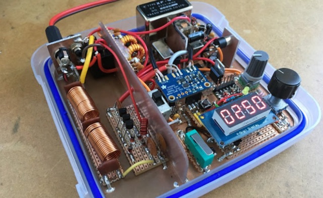 Homemade portable transceiver for the 40 meters band.
 -
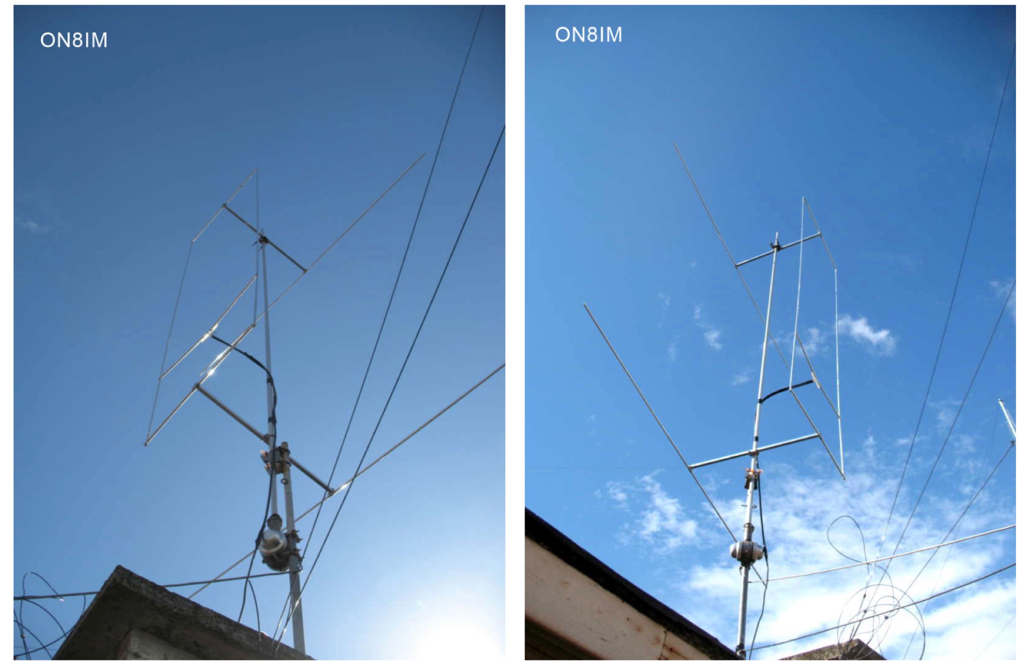
 A cost-effective alternative to the Optibeam OB10-3W, a high-performance but expensive tri-band Yagi antenna for the 20, 17, and 15-meter bands. The original Optibeam, featuring three full-size elements on each band, delivers strong forward gain and front-to-back ratio but comes with a high price tag. To address this, a custom design was developed, offering similar performance at a fraction of the cost. Using accessible materials and a simple 1:1 current balun, the homemade version proved highly effective, making it a practical solution.
 -
 Demonstrates the construction and portable deployment of a 40-meter horizontal loop antenna, often referred to as a "Sky Loop" or "DX-Buster." The design adapts a full-wavelength horizontal loop for field use, eliminating the need for traditional insulators by employing four 5-meter heavy-duty _squid poles_ and metal post bases for support. This setup facilitates rapid assembly, crucial for portable operations, with the antenna wire length specified at approximately 43-45 meters for optimal 40-meter band performance. The resource details the specific construction methodology, including winding the antenna wire around rubber caps on the squid poles and securing it with electrical tape. It provides a parts list and assembly techniques, focusing on minimizing components for ease of transport and quick setup. The article, originally published in the February 2013 edition of the Central Coast ARC "Smoke Signals" magazine, reflects practical experience. This documentation offers a field-deployable 40-meter loop antenna solution, utilizing readily available components like fiberglass squid poles. It presents a practical approach for operators seeking a robust, portable antenna for the 40-meter band, emphasizing simplicity and efficiency in its design and deployment.
 -
 The Beverage on Ground (BOG) antenna offers ham radio operators a compact alternative to traditional Beverage antennas, requiring less space and fewer support structures. This implementation, optimized for 1.8-7 MHz bands, describes ideal parameters: lengths of 60-90 meters, height of 2-10 cm above ground, and specific load resistances based on configuration. The article details experimental methods for determining optimal load resistance and presents matching systems to convert BOG impedance to 50 ohms. While less effective than classic 200-300 meter Beverages, the BOG provides directional reception in limited space, though performance varies with ground conditions and weather changes.
 -
 Discover how to easily listen to amateur radio bands with insights from Frank SWL, an experienced radio enthusiast. This guide covers essential tips for tuning into frequencies between 10 meters and 160 meters using modern tools like Web SDR and Kiwi SDR. Learn about identifying callsigns, understanding Q codes, and optimizing your antenna setup for better reception. Whether you're a beginner or an experienced listener, this article provides practical advice for enhancing your radio listening experience in 2025.
 -
 The 1/4 wavelength vertical antenna project, initially designed for 20 meters, has evolved into a versatile portable solution covering 10 through 60 meters. K0BXB details its construction, emphasizing a bottom-loaded design with a tapped loading coil and four 10-foot counterpoise wires. The author shares personal experiences and field results, including **18 QSOs** during a park activation on 17m and 30m with 10 watts, and a **2,435-mile** contact with a contest station in Bonaire on 20m using 5 watts. Comparisons are drawn to commercial offerings like the _Wolf River Coils TIA_ and _QRPGuys Triband Vertical_, highlighting the DIY antenna's small footprint, light weight, and ease of tuning for POTA activations. The resource includes insights into using test equipment such as the _NanoVNA_ for SWR optimization and discusses various radiator lengths, from 17-foot wire to a 102-inch whip, demonstrating adaptability for different portable setups. Construction tips cover coil winding, tap placement, and connecting feedlines and radials using common components.
 -
 Discover the secrets of Six Meters with this comprehensive eBook by Jim Wilson, K5ND. Learn about the magic of 6-meter DXing, including propagation, antennas, equipment, operating software, and more. Whether you're a beginner or an experienced ham radio operator, this book covers everything you need to know. With over 8,000 downloads, this updated version includes new chapters on FT8/FT4, MSK144, and Q65 modes, as well as contesting, rover operation, and awards. Get your hands on this valuable resource and enhance your 6-meter DXing experience today.
 -
 Chavdar Levkov, LZ1AQ, presents an experimental comparison of small wideband magnetic loops, building on his previous work on wideband active small magnetic loop antennas. His research focuses on increasing loop sensitivity by maximizing the short-circuit current, which is directly tied to the "loop factor" M = A/L, where A is the equivalent loop area and L is its inductance. Levkov's methodology involves reducing inductance and increasing area through parallel or coplanar crossed (CC) configurations, comparing these designs against a reference single quad loop of 1 m2 area. Experimental verification included testing three distinct loop types: a simple quad loop, two coplanar crossed (CC) loops, and eight parallel loops, all designed to have a total geometric area of 1 m2. Measurements were conducted at 1.8, 3.5, 7, and 10 MHz using a small transmitter 270 meters away, with a Perseus direct sampling receiver for precise signal level assessment. The results consistently showed that CC loops, particularly Loop 5 (two CC circular loops with 1.44 m2 total area), yielded significantly higher currents, up to 9.1 dB over the reference loop at 3.5 MHz, validating M as a reliable predictor of loop sensitivity. Numerical simulations using MMANA further corroborated the experimental findings, demonstrating an almost perfect correlation between the calculated M factor and the induced loop current for 15 different loop models. Levkov concludes that CC loops offer superior sensitivity for a given loop area, while parallel loops are advantageous for minimizing physical volume. Practical recommendations suggest using loops with an M factor greater than 0.5 uA/pT for quiet rural environments, and he provides a spreadsheet tool, WLoop_calc.xls, to aid in optimizing loop configurations for specific operational needs.
 -
 The article by Guy Olinger, K2AV, published in the May/June 2012 National Contest Journal, introduces the Folded Counterpoise (FCP), a compact 516-foot single-wire counterpoise elevated at 8 feet, designed for 160-meter operations on small lots like 100x150-foot backyards. Originating from efforts to revive Top Band for W0UCE on a postage-stamp property, the FCP uses strategic folds to cancel ground fields within 33 feet of center, minimizing losses to 0.13-0.53 dB—outperforming sparse or on-ground radials by up to 15 dB in poor soil—while mimicking opposed radials for efficient feedpoint impedance. Paired with a critical 1:1 or 4:1 isolation transformer (e.g., trifilar on T300-2 toroid) to block common-mode currents on coax feeds, it delivers proven results: K2AV's #8 North America low-power contest score, 7+ dB gains at W4KAZ and K5AF, and over 10,000 global web hits for DIY instructions using bare 12 AWG wire and weatherproof enclosures. Ideal for acreage-challenged hams, the FCP also excels on 80 meters with scaled dimensions, offering a low-loss alternative where full radials are impractical
 -
 Explores the addition of a reflector to the traditional Hentenna design for 6m band, providing construction insights, performance comparisons, and modeling data
 -
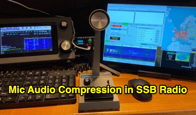 Single-sideband (SSB) radio enhances spectral efficiency but poses challenges with audio intelligibility, particularly in noisy conditions. A microphone audio compressor addresses these issues by dynamically managing the audio signal’s dynamic range. It amplifies quiet sounds and attenuates loud ones, ensuring consistent audio levels for improved clarity. Benefits include increased intelligibility, higher average power, and reduced spurious emissions. While essential for optimal SSB performance, careful parameter adjustment is crucial to balance natural sound quality and effective communication across various operating modes.
 -
 This article presents a novel Top Loaded End-Fed Half-Wave (TLEFHW) antenna design for 20-meter ham radio operation. The antenna features a compact 14-foot vertical radiator with a capacitance hat configuration, eliminating the need for radials or ground systems. Using EZNEC modeling and field testing, the design achieves a 1.5:1 SWR across the 20m band with a 4.11 dBi gain. Key features include quick deployment, lightweight construction, and directional radiation pattern with 110-degree beamwidth. The design, while requiring a 45-foot footprint due to the top hat, offers an effective portable solution for amateur radio operators seeking a no-ground, no-tuner 20m antenna option.