Search results
Query: google com ig
Links: 385 | Categories: 0
-
 Examines the practical considerations and technical challenges of deploying mobile antennas for 10-meter operation, particularly for operators on the move. It addresses the inherently _lossy_ nature of shortened, loaded vertical antennas typically used in mobile configurations, encouraging hams to view these limitations as engineering challenges. The resource provides actionable advice on safeguarding vehicle electronics, selecting appropriate cabling like _RG-213_, and properly grounding antenna mounts to the vehicle chassis. Specific mounting strategies are detailed, including roof, trunk lip, and side-mounting for trucks and vans, along with their respective advantages and drawbacks. It emphasizes the importance of a robust ground plane and suggests methods for improving grounding beyond simple set screws. The article also touches on antenna choices, mentioning "bugcatchers" and "Hamstick types" as viable options for 10 meters. Furthermore, the guide transitions to stationary mobile operation, where antenna options expand significantly. It outlines how to deploy portable dipoles or 2-element beams from a parked vehicle, offering practical tips for assembly, storage, and mast guying using simple materials like a concrete block. It notes that a 5/8 wavelength height, approximately **20 feet** on 10 meters, often yields good short-skip and DX performance, even with a take-off angle above **20 degrees**.
 -
 A **90-foot tall** top-loaded vertical antenna for the 160-meter band is detailed, constructed from aluminum irrigation tubing. The design incorporates four sets of four guy wires for structural stability, essential for an antenna of this physical size. This _monoband_ vertical is optimized for low-band operation, providing a robust solution for DXing and contesting on 1.8 MHz. The document includes specific construction methods for assembling the aluminum irrigation tubing sections and securing the guy wires. While a full NEC model is not explicitly provided, the physical dimensions and construction materials are sufficient for replication by experienced builders. The antenna's height and top-loading configuration are critical for achieving efficient radiation on 160 meters, particularly in minimizing ground losses.
 -
 KaWin is a Windows software that supports multiple Kantronics TNCs and multiple radio transceivers with an intuitive, graphical interface, setting a new standard of performance for digital radio communications. Software is not supported anymore.
 -
 The resource details the construction and performance of a dual-band 40/30 meter _Moxon_ antenna, evolving from an initial single-band 30-meter design that failed in a storm. It specifies materials such as four 10-meter fishing rods, galvanized iron TV antenna support pipes, 1mm diameter PVC-covered copper wire, and a piece of 75-ohm TV satellite cable for feedline. The document outlines the iterative design process, including initial resonance measurements of 9.9 MHz for 30 meters and subsequent recalculations to shift the center frequency by 300 kHz using _Moxon software_. Initial testing on a roof yielded SWR readings of 1.4:1 at 7.200 MHz and 1.5:1 at 10.280 MHz. After installation atop a 30-meter tower, the final SWR measurements were 1.1 at 7.130 MHz and 1.4 at 10.230 MHz, with a notable 30 dB front-to-back ratio on 40 meters. The 30-meter performance, while good, showed a front-to-back ratio of approximately 15 dB, suggesting a slightly high resonance. The antenna's placement on a 700-meter hill, with a significant ground drop in certain directions, is noted as a potential factor in its excellent DX performance, enabling daily contacts with the USA West Coast on 30 and 40 meters with 100 watts.
 -
 The W8JK is a famous and effective DX antenna, first built by John Kraus, W8JK, in 1937. A Beam antenna with two parallel dipoles driven with opposite phase, with a close spacing of an eighth of a wavelength.
 -
 This program descrambles band inverted encrypted transmissions, usually found on VHF/UHF. It uses a NCO (numerical controlled oscillator) to re-produce the originally inverted audio band.
 -
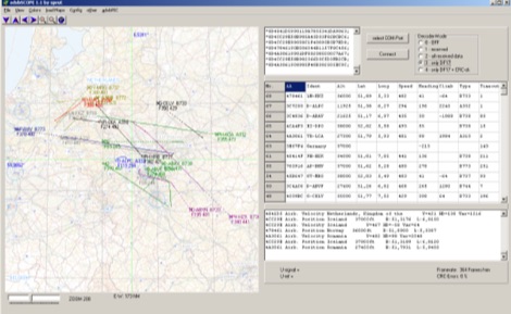 adsbScope is a freeware Windows application designed for processing _ADS-B_ (Automatic Dependent Surveillance-Broadcast) frames received from a compatible decoder. It identifies aircraft, calculates their real-time positions, and presents flight parameters in both alphanumeric tables and a graphical display. The software interfaces via a virtual COM port, receiving raw frames to provide detailed situational awareness, including a global coordinate grid, continental coastlines, over 4,000 **airport** locations, and major cities. Users can overlay OpenStreetMap tiles and view world state boundaries, with each tracked aircraft rendered with labels showing altitude, speed, heading, squawk code, and flight identifiers. When paired with the adsbPIC-decoder, adsbScope enables advanced hardware control, allowing users to toggle data filters for specific frames like DF17/18/19, adjust analog signal thresholds for reception fine-tuning, and manage system resets or bootloader activation directly from the PC. This functionality provides a customizable toolkit for hobbyist radar listeners, offering a robust alternative to commercial tools for processing aircraft data. The software displays up to **1090 MHz** transponder data and can track aircraft up to 250 nautical miles.
 -
 Presents G0GSF Brian's ZS6BKW antenna, a refined iteration of the classic G5RV, offering improved performance across multiple HF bands. The design emphasizes specific radiator and ladder line lengths to achieve lower SWR on 40m, 20m, 17m, 12m, and 10m, making it a practical choice for operators seeking a single wire antenna solution. The document includes critical dimensions for the flat-top and the 450-ohm ladder line section, which are key to its multiband resonance characteristics. Unlike the original G5RV, the ZS6BKW aims for direct 50-ohm feedpoint impedance on several bands, reducing the need for an external antenna tuner. My field experience with similar optimized dipoles confirms that precise construction, particularly the ladder line length, is paramount for realizing the intended SWR benefits. This design offers a compelling alternative for hams with limited space or those preferring a less complex antenna system.
 -
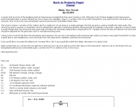 Demonstrates building a basic _VOX circuit_ to add voice-operated transmit functionality to HF transceivers that lack this feature. The design utilizes a _1458 dual op-amp_ (two 741 op-amps in one package) to amplify microphone audio and act as a comparator, driving an NPN switching transistor for PTT control. A capacitor, C2, provides the necessary delay before unkeying the PTT, with a variable resistor, R6, allowing adjustment of the VOX level for specific microphones or voices. This low-cost circuit, detailed with a full parts list, offers a practical solution for hams seeking to enhance their budget HF rigs. The author, N1HFX, provides guidance on initial setup, including advice on microphone gain and the use of headphones to prevent speaker audio from re-keying the transceiver. Modifications for adjusting delay time are also included, suggesting increasing R8 to 10K for more delay or decreasing C2 to 22µF for less.
 -
 NuMorse 2.20.0.0 for Win 7/Win 8/XP/Vista/Win 10 A complete rewrite of the original NuMorse used by thousands of radio amateurs to gain and upgrade their licenses. NuMorse offers an intermediate feature set that is somewhere between the lean and mean NuCode program and the vast array of features supported by NuMorse Professional. But NuMorse is no cut-down program. It has several unique features not found in other Nu-Ware products as well as a compact and intuitive set of controls that you will be able to learn quickly.Product is no more developed and out of support.
 -
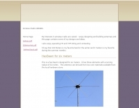 This is a hex beam designed for six meters. It has three elements with a turning radius of 54 inches. This antenna can be built from low cost materials available from the local hardware store. By WB3BEL
 -
 The original G5RV antenna system consists of a center-fed horizontal 102' wire plus a 34' length of open-wire 525-Ohm feeder. Louis Varney, the antenna system's developer, intended two other features. Learn more at Cebik website
 -
 A PIC16F876 microprocessor-based digital SWR/WATTmeter project provides automatic operation across the 1.8 to 60 MHz frequency range. This design displays both SWR and P.E.P. power values, incorporating a bar graph on the second LCD line for instantaneous power tracking. The directional coupler utilizes a single-wire coil on a ferrite FT50-43 toroid, balanced with a 60 pF trimmer, and employs 1N5711 Schottky diodes for detection, ensuring linearity and a power range of 5 to 120 W. The software, developed by IW3EGT, compensates for diode voltage drop for precise readings, updating power every two seconds for stable display of modulated carriers, while the bar graph updates ten times per second for near real-time feedback. Calibration involves two phases: adjusting the directional coupler for minimum SWR on a 50-ohm dummy load at 28 MHz, and calibrating the microprocessor system by inputting a calculated power value (Power (Watt) = (Vout + 0.5)^2 / 100) at 14-21 MHz. The project includes PCB layouts for both the directional coupler (two-layer copper board) and the PIC module (single-sided), with specific instructions for component placement and shielding to prevent RF interference. The design allows for modification of power reading capability by varying the number of turns in the coupler coil, catering to different power levels.
 -
 A 40-meter reversible _Moxon rectangle_ antenna project details its construction and performance, featuring 51-foot long sides and 7.7-foot turned-in sections. The design incorporates a 16.5-foot boom, with elements spaced 1.1 feet apart, constructed from #14 covered wire. It utilizes two double-pole relays for switching between NE and SW directions, achieving F/B ratios up to 40 dB on CW and 30 dB on SSB, with distinct reflector stub settings for each mode. This antenna replaced a full-size 2-element Yagi, demonstrating comparable forward gain while offering superior F/B ratios and directional flexibility. _EZNEC_ modeling indicates only 0.2 dB less forward gain than the Yagi. The system uses no baluns, relying on half-wave feedlines and switched stubs for impedance matching. The antenna is tree-supported at 45 feet, with its effective radiation height modeled at 80 feet due to local terrain, enhancing its performance over a nearby lake.
 -
 The "Largest YU Moxon" document details the design and construction of a substantial multiband Moxon antenna, primarily for 80m, 40m, and 20m operation. It presents specific design parameters derived from NEC-based simulations, including a 4-element 80m Moxon with 37 dB F/B and 7.81 dBi gain on a 47m boom, a 4-element 40m Moxon with a bidirectional pattern, and a 6-element 20m Moxon optimized for specific side lobes. The resource provides precise element lengths and spacing in meters for each band, alongside measured SWR results across the 3.650-3.800 MHz, 7.000-7.100 MHz, and 14.000-14.350 MHz segments. The construction narrative outlines the challenges and solutions encountered by the YU team, including the use of trees for support, the creation of "ugly" air-choke baluns from RG-58 cable wound on plastic bottles for each band, and the meticulous process of attaching wires to a rope boom. It documents the physical dimensions of the vineyard site (47 x 38m) and the azimuth orientation (340 degrees) chosen for the antenna. The document is distinctively useful for its practical insights into large-scale antenna deployment in a field environment, offering real-world SWR measurements and anecdotal performance reports from CQWW contest operations. It includes numerous photographs illustrating the construction process, the team members, and the finished antenna structure, providing visual context to the technical details.
 -
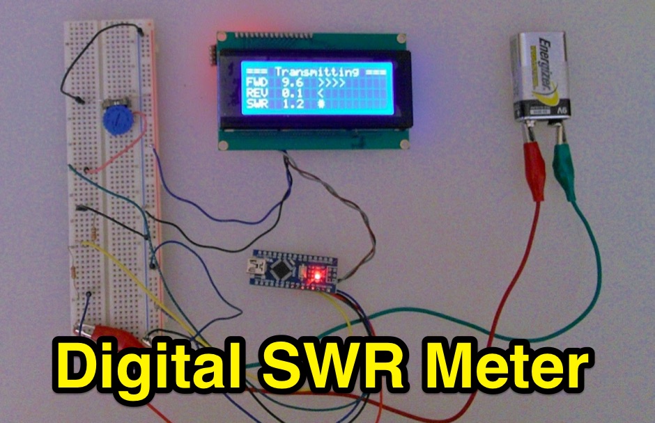 Inline RF Power & VSWR Meter. A DIY meter 0 to 30 Watt with Average and Peak. Circuit Description, Arduino Nano software code and part list to DIY your own Digital SWR Meter
 -
 Designing quagi and yagi antennas on 2 Meters, some preliminary notes by Cebik, W4RNL
 -
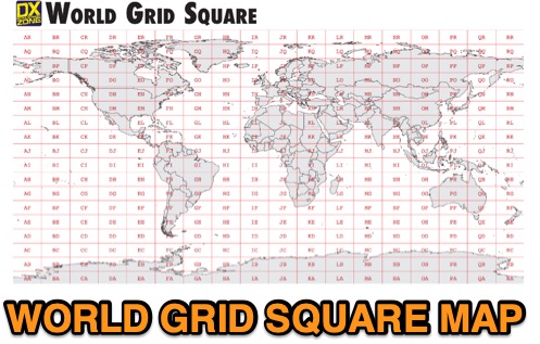 This free PDF file contains two Worldwide grid square maps. The first map displays the fields (first two letters of a maidenhead locator) while the second includes also squares (third and fourth digit) and it can be useful to determine what is your ham radio grid square. PDF file can be enlarged and scaled to A3 and higher dimensions.
 -
 Great first time J-pole project. Covers most of the basics. This small and thin design also makes it good for several stealth applications.
 -
 This PDF document, authored by KT4QW in October 2004, details the construction and modeling of a dual-band, horizontally polarized hanging rectangular loop antenna for **10 and 17 meters**. The design, adapted from *The ARRL Handbook*, utilizes _NEC4WIN95_ software for scaling and optimization, targeting a 50 ohm feedpoint impedance. The resource includes a bill of materials, step-by-step construction instructions, and a discussion of the antenna's radiation characteristics. It presents NEC-generated elevation and azimuth patterns, comparing the loop's performance to a half-wave horizontal dipole at the same height and frequency. The 17-meter element is centered at 18.140 MHz for low SWR across the phone band, while the 10-meter element is centered at 28.500 MHz. Construction involves 14-gauge stranded copper wire and Schedule 40 PVC spreaders, with the total wire length calculated by the formula: Length in feet = 1005/MHz. The feedpoint impedance can be adjusted by modifying the rectangular aspect ratio. The document specifies hoisting the antenna to at least a half-wave above ground for testing. It notes that a balun was tested and found to have no measurable effect on SWR or radiation characteristics. A 2-meter scale model is presented to illustrate the physical design, and a "rotator" string is incorporated for directional adjustment up to 90 degrees.
 -
 Designing a compact directional antenna for the 70cm band involves balancing gain, front-to-back ratio, and physical size. This resource details the construction of a 2-element Moxon rectangle antenna for 432 MHz, outlining the specific dimensions for the driven element and reflector, and discussing the advantages of its folded dipole configuration. The article provides insights into the historical context of 70cm operations and the author's personal experiences with early 432 MHz transceivers and antenna setups, such as a Jaybeam 48-element TV antenna. It also touches upon the practical aspects of building and deploying such an antenna for local and weak-signal work. The Moxon antenna design is compared to a 3-element Yagi, noting its superior front-to-back ratio and broader bandwidth for a given boom length, making it suitable for portable operations or restricted spaces. The construction uses readily available materials like copper wire and PVC tubing, emphasizing simplicity and ease of replication. Performance characteristics, including a reported gain of approximately 5.5 dBi and a front-to-back ratio of 20 dB, are discussed in the context of its compact footprint. The resource includes a visual representation of the antenna's dimensions and construction, aiding in practical implementation.
 -
 An antenna does not have to be resonant to work, as the primary reason for resonance is to eliminate the need for an impedance-matching device. A non-resonant wire dipole fed with open-wire line and an antenna tuner can function as an effective multiband antenna. Two wires are essential for powering an antenna, ideally with a balanced configuration like a dipole fed by parallel-wire line, though coaxial cable can be used with a 1:1 balun to mitigate RF feedback on the shield. Antenna gain is achieved by shaping and aiming RF energy, concentrating it in a particular direction, as seen in beam antennas or shaped radiation patterns of wire antennas. The function of an antenna tuner is to match the transceiver's 50 Ohm output to the antenna system's impedance, which can vary widely. Wire antennas do not always require center feeding; end-fed long wires or off-center-fed dipoles (Windom antennas) can be used, often requiring a counterpoise or radial system. Dipole antennas do not need to be perfectly horizontal; their legs can be bent, inclined, or even vertical, affecting feed point impedance. Vertical antennas shorter than a half wavelength necessitate a ground system, typically comprising radial wires, with more radials generally leading to greater efficiency. A 1:1 SWR indicates an impedance match but does not guarantee a good antenna, as an inefficient antenna with a poor ground system can still show a perfect SWR while wasting RF as heat. Always using the best feed line affordable is crucial for minimizing loss and maximizing RF signal delivery to and from the antenna.
 -
 These inexpensive, easily built filters can be the buffer you need between the signals you want to hear and send and those you don't!
 -
 This technical note explores the application of **Moxon rectangle** antennas for WARC bands, specifically 17 and 12 meters, as compact directional alternatives to standard Yagis. It details three design approaches: a dual-band Moxon using open-sleeve coupling, a Moxon-Yagi combination, and a simplified 1.5 Moxon rectangle. The document provides specific dimensions in feet for aluminum tubing elements (0.75" and 0.5" diameter) for each configuration, along with projected free-space gain, front-to-back ratio, and feedpoint impedance (R+/-jX Ohms) across the respective band segments. Performance tables illustrate gain (dBi), front-to-back ratio (dB), and 50-Ohm VSWR for each design. The dual-band Moxon, despite its compact 7-foot boom, is not recommended due to extreme sensitivity to construction variations, leading to rapidly changing performance characteristics. The Moxon-Yagi combination, featuring a 17-meter Moxon and a 12-meter director-driver Yagi, is presented as a more practical and adjustable solution, offering stable performance with a 10-foot boom. NEC model descriptions are included for simulation in programs like EZNEC, NEC-Win Plus, AO, or NEC4WIN.
 -
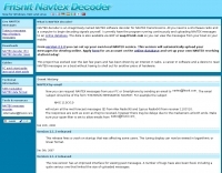 Approximately 400 kHz is the primary frequency for Navtex broadcasts, a crucial maritime safety information system. This legacy software, _Frisnit Navtex Decoder_ version 2.1.5, provides a means to decode these messages directly from an amateur radio receiver's audio output, fed into a PC's microphone input. It operates by processing the audio stream, extracting the FSK (Frequency Shift Keying) data, and presenting the decoded text on a Windows platform. Despite being unsupported and no longer under active development, the application remains functional across a wide range of Microsoft operating systems, from _Windows 95_ through _Windows 11_. Its utility lies in offering a straightforward, no-cost solution for hams and SWLs interested in monitoring Navtex transmissions without specialized hardware. The software's design focuses on simplicity, allowing users to quickly set up and begin decoding maritime weather forecasts, navigation warnings, and other safety-critical information. It leverages the PC's sound card, making it accessible with minimal additional equipment beyond a receiver capable of tuning to the Navtex frequencies.
 -
 The N0KHQ Coax Square antenna, designed for 17 meters and built using RG-58 coaxial cable, presents an intriguing option for hams with limited space. L. B. Cebik, _W4RNL_, meticulously models and analyzes this array, clarifying its classification not as a modified Moxon, but as a distinct member of the "dual-coupled, 2-element, parasitic array" family. The design leverages the velocity factor of RG-58 (approximately 0.66-0.67) to achieve significantly shorter element lengths compared to full-size counterparts, resulting in a perimeter of 42 feet for the N0KHQ array versus 54 feet for a standard Moxon. _NEC_ modeling reveals the coax square's performance characteristics, including a forward gain of 5.6 dBi and a 23.7 dB front-to-back ratio on 18.118 MHz. While slightly less gain than a Moxon (6.0 dBi), its pattern exhibits Yagi-like nulls at 90 degrees, distinguishing it from the Moxon's wider beamwidth. The article also delves into the unique feedpoint considerations, explaining how the split braid and center conductor of the RG-58 driver effectively form a folded dipole, allowing for impedance transformation to achieve a good match for 50-Ohm cable. Despite its shortened elements, which inherently narrow the operating bandwidth, the coax square maintains satisfactory performance across the 17-meter band. The analysis emphasizes that while SWR curves are important, a holistic view of gain and pattern degradation across the band is crucial. This antenna is a viable solution for operators needing a compact, directional array, particularly for narrow bands like 17, 30, or 12 meters, where its high-Q performance is most effective.
 -
 An experimental antenna, similar to the _TAK spiral antenna_, was evaluated for SWR response over the 7.0 to 7.3 MHz frequency range. The analysis presents specific results: beam length significantly affects SWR, with increased distance between spirals raising the resonant frequency; the combined length of antenna and hookup wire lowers the resonant frequency as it increases; and spiral diameter impacts bandwidth, with larger diameters yielding greater bandwidth. The design addresses the fixed beam length limitation of the commercial TAK antenna by introducing an adjustable version constructed primarily from PVC electrical conduit and water pipe, using 14-gauge aluminum wire. The resource includes a detailed mechanical design, construction steps, and a parts list. It also features a spiral antenna spreadsheet model for calculating design parameters like start point, pitch, safe edge, spoke length, and arm length, which aids in determining wire length and kerf cutting tables. Model verification involved constructing an antenna to specific parameters, with SWR tests conducted using an _MFJ Model 269_ antenna analyzer at 13 feet above ground with 60 feet of RG8 mini coax. Measurements showed that adjusting beam length from 27 to 37 inches shifted the resonant frequency by approximately 0.18 MHz. Further data compares 32-inch versus 48-inch diameter spirals, demonstrating increased bandwidth for the larger diameter. The model accurately predicted revolutions for given antenna lengths, pitch, and starting distances. The final design achieved a resonant frequency of 7.17 MHz, favoring the voice portion of the 40-meter band after adjustments.
 -
 The document details the optimization and construction of the _Maria Maluca_ antenna, a compact 6-band (20m-6m) directional beam. It presents a comparative analysis of shortwave antenna principles, highlighting the efficiency gains achieved by using an open feeder line and tuner as a resonant unit, contrasting this with the losses associated with traps or capacitive loads in multiband antennas. The resource specifically revisits an older South American 2-element design for 10, 15, and 20 meters, applying modern NEC-based software to develop a six-band version. Performance data is meticulously tabulated, showing impedance, free space gain, gain at 12m height, elevation angle, and front-to-back (F/B) ratio for each band from 20m through 6m. For instance, on 15m, the antenna achieves 5.1 dBd free space gain and 13.72 dB F/B ratio. The construction section provides practical guidance on element assembly using aluminum pipes and hose clamps, detailing the use of a heavy-duty glass fiber reinforced polyamide rod for electrical separation and bending strength. It also specifies the use of 450-ohm _Wireman_ line CQ 552 for the transmission line. The document includes diagrams for rod fixing, an air-wound balun, and a vertical elevation diagram for the 15m band, illustrating its DX qualification. It also discusses the antenna's suitability for portable and expedition operations, noting its compact transport dimensions (max 1.50m length, 12 lb weight) and quick assembly time (under 15 minutes). The author, Dipl.Ing. Helmut Oeller, DC6NY, is identified as a source for material kits.
 -
 W1ZY's 40-meter **Moxon** antenna project details nine months of experimentation, culminating in a reversible array built from No. 12 insulated wire. The design incorporates two RF current baluns and a unique two-wire element construction, where each element consists of two parallel wires spaced 3 inches apart. The resource provides specific dimensions for the first prototype, including A=50.98', B=7.87', C=1.25', D=9.3', and E=18.42', optimized for 7.050 MHz CW operation. It thoroughly explains the construction of custom two-wire insulators from Plexiglas semi-rods and the critical pre-tensioning process required to maintain wire separation and array integrity. The author, Bill, emphasizes the antenna's exceptional receive performance, noting a 30-35 dB front-to-back ratio, which allows for significant signal rejection from the rear. While the Moxon offers 5-6 dB gain on transmit, its primary advantage lies in its ability to radically reduce rear-facing signals on receive, a characteristic Bill believes is often overlooked in transmit-focused comparisons. The guide details a flexible tuning method using removable tail-end jumpers, enabling adjustments to both tail-end and parallel dimensions without re-soldering the feed point, a technique refined over three prototypes.
 -
 Theory, Modeling, and Practical Applications By W5JCK, presentation in PDF File. This presentation focuses on Near-Vertical Incidence Skywave (NVIS) antennas, which are crucial for short-range radio communications, particularly in military and emergency contexts. It explores NVIS theory, antenna models, and installation criteria while debunking common myths about reflectors. Key topics include usable frequency bands, optimal installation heights, and the impact of soil quality on performance. The presentation outlines the best bands for daytime and nighttime use, emphasizing the importance of understanding propagation characteristics to enhance communication effectiveness within 200 to 300 miles.
 -
 Interesting variant on the 3-element Yagi. Lightweight fiberglass (or similar) tubes supporting a wire structure of elements
 -
 The article "Exploring the World of 10 Meter Beacons" by Ken Reitz, KS4ZR, provides an in-depth look at 10-meter beacon operations, focusing on their utility for propagation analysis. It details FCC Rules part 97.203 governing beacon stations, including license requirements, power limits (under 100 watts), and the specified band segment of 28.200-28.300 MHz for U.S. operations. The content highlights the diversity in beacon construction, from converted CB radios to home-brew QRP transmitters, and discusses the robust operating conditions these 24/7 stations endure. The resource presents several case studies of active 10-meter beacon operators like Ron Anderson KA0PSE/B, Domenic Bianco KC9GNK/B, and Bill Hays WJ5O/B, detailing their equipment, antenna setups, and typical signal report volumes. It also introduces the NCDXF/IARU International Beacon Project, which features 18 synchronized beacons worldwide transmitting on 28.200 MHz at varying power levels (100W, 10W, 1W, 100mW) to facilitate propagation testing. The article also covers the PropNet Project utilizing PSK31 on 28.131 MHz and the 250 Synchronized Propagation Beacon Project on 28.250 MHz. Practical advice for monitoring includes using the RST reporting method, understanding the impact of the solar cycle on 10-meter propagation, and tips for setting up a personal beacon, such as frequency selection and power output considerations. The IY4M Guglielmo Marconi Memorial Beacon Robot on 28.195 MHz is also mentioned for its automatic QSO mode. The article concludes with a list of other resources for 10-meter beacon information.
 -
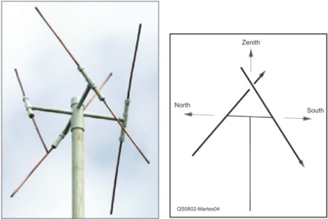 An easy to build antenna for ground reception of NOAA weather or amateur satellite signals. Double cross antenna by Gerald Martes
 -
 The 10-meter EH Antenna document details the construction and performance of a specific EH antenna design for the 10-meter band. It describes the integration of an L+L balanced matching network, a key component for impedance transformation, and highlights the addition of a tuned coaxial trap. This trap, consisting of 8 turns of RG58 coax wound around PVC tube and resonated at 29 MHz with a 10 pF capacitor, effectively inhibits common-mode current on the feeder, stabilizing antenna tuning. The resource presents a circuit diagram in Figure 1 and assembly details in Figure 2, illustrating the use of PVC plumbing tube as host material for dipole cylinders made from recycled aluminum tubing. It also explains the fabrication of capacitor stators and slider sections from thin aluminum tubing. The author, Lloyd Butler VK5BR, discusses initial challenges with feeder interaction and how the tuned trap resolved these issues, leading to stable tuning. Limited backyard tests indicate that the antenna, with the trap fitted close to the input connector, might exhibit similar field strength for both low and high angle transmission, suggesting a potential skewing of the signal. The document references previous articles by VK5BR in "Amateur Radio" for further operational details of the matching network and trap functionality.
 -
 Managing extensive amateur radio contact logs efficiently requires specialized software that integrates various operational aspects. Aether provides a macOS-native logging solution, designed from the ground up using Apple's Cocoa, to streamline QSO entry, organization, and retrieval for Mac users. It supports modern macOS technologies and offers an intuitive interface, aligning with the user experience expected on Apple platforms. The application includes features such as automatic dupe checking, which quickly identifies previous contacts with a station, and awards tracking, indicating if a new contact is needed for specific operating awards. Aether also integrates rig control via RS-232, automatically populating frequency, mode, and power data from supported Elecraft, Icom, Kenwood, Yaesu, and some TEN-TEC transceivers. This automation reduces manual entry errors and speeds up the logging process. Furthermore, Aether offers comprehensive QSL management, including synchronization with eQSL.cc and Logbook of The World, and the ability to print QSO detail and address labels for paper QSLs. It also incorporates automatic callbook lookup from sources like QRZ.com and HamQTH.com, and calculates distance and beam heading, with Google Maps integration for visualizing contact locations. Full ADIF and Cabrillo import/export capabilities ensure compatibility with other logging software and contest submission platforms.
 -
 Vox Recorder is a Windows utility wich allows recording sound from an audio source only when an audio signal is present; its main purpose is to avoid the recording of the silence eventually present at the input.
 -
 Stream is a software that implements MFSK16 and MFSK8 modes designed by me and Murray Greenman ZL1BPU. It also offers a series of experimental modes based on FEC, interleaving and several modulation techniques (PSK, QPSK, MSK).
 -
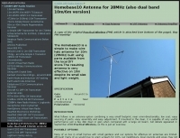 The Homebase10 is a simple to make wire halo antenna for 10m (28MHz) built using parts available from the local DIY store.The resulting antenna is very effective on 10m despite its small size and light weight.
 -
 Build a 5 watt, 80 meter QRP CW Transceiver Designed by N1HFX
 -
 Demonstrates a practical modification to convert a standard G5RV antenna into a _160-RV_ for effective operation on the 160-meter band. This project addresses the challenge of achieving Top Band resonance with a common multi-band wire antenna, providing a solution for hams with limited space or resources for dedicated 160m antennas. The design utilizes a specific length of 450-ohm ladder line and a 1:1 current balun, acting as a matching section to bring the G5RV's impedance into a usable range for 1.8 MHz. The document includes a parts list, detailed construction steps, and tuning instructions, emphasizing the importance of precise measurements for the ladder line and coaxial cable sections. It also outlines the expected SWR characteristics and power handling capabilities, making it suitable for QRO operation up to 1.5 kW. The _AD1B_ design offers a straightforward approach for extending the utility of an existing G5RV.
 -
 Very strange morse keyers, like Onion chopper CW key, Handshake CW key, Chopsticks CW key, Typewriter CW keyboard, Refrigerator CW key by OH6DC
 -
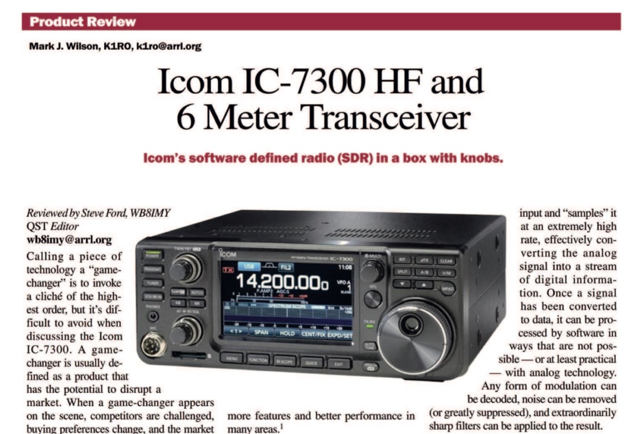 The ICOM IC-7300 is a cutting-edge HF transceiver that has garnered significant attention since its release. This review, published by ARRL in QST, provides an in-depth analysis of its features, performance, and usability. The IC-7300 is known for its direct sampling technology, which enhances its sensitivity and selectivity, making it a favorite among amateur radio operators. The review covers various aspects, including the user interface, audio quality, and overall operational capabilities, providing valuable insights for both new and experienced hams. In addition to its technical specifications, the review discusses the IC-7300's performance in real-world scenarios, such as DXing and contesting. It highlights the transceiver's ability to handle weak signals and its versatility across different modes. The review serves as a helpful guide for those considering the IC-7300 for their station, offering a balanced perspective on its strengths and potential drawbacks. Overall, this review is an essential resource for anyone interested in the ICOM IC-7300 and its place in the amateur radio landscape.
 -
-
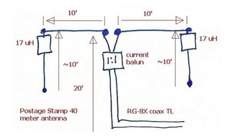 Build yourself a postage stamp 40 meter wire dipole antenna that fits in a space a little over 20 wide and works reasonably well at low heights
 -
 A 40 80 dipole antenna design by WA6ESC PDF File
 -
 Lets you listen to your scanner across your own network, or via the internet. Shoutcast/ICEcast compatible broadcasting for Uniden and GRE scanners. Broadcast your audio from your PC. ScannerCast is a specialized broadcasting solution that enables users to stream scanner audio feeds over the internet. This software supports both Uniden and GRE scanner models with tag information capability, while providing audio-only functionality for other scanners. Compatible with standard streaming protocols, ScannerCast allows remote listening via common media players without requiring specialized client software. The program features customizable tag display, adjustable bit rates, and seamless integration with Radio Reference. Its efficient design replaces multiple legacy applications while improving tag/audio synchronization. ScannerCast operates efficiently across various Windows environments, making remote scanner monitoring accessible from any location with internet connectivity. Scannercast is no more supported or developed by it's author.
 -
-
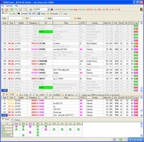 RDXCluster is a free windows telnet client for worldwide DX packet Cluster,featuring multiple spot windows, Band/Mode DXCC window, DX History window, Top DX window, Find, highlights, filters the spot by Roberto Verrini
 -
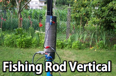 A homebrew fishing-rod vertical using a very nice design from EB5EKT. This antenna works 20, 30, and 40M bands by selecting the tap points using alligator clips
 -
 K6ZB Bruce presentation of technologies to allow ham radio operate via internet