Search results
Query: reception antenna
Links: 121 | Categories: 4
-
 Presents the Holy Cluster, a contemporary DX cluster service offering real-time amateur radio spot data. This platform integrates a dynamic graphical map to visualize current contacts, enhancing situational awareness for DXers and contesters. Developed by an Israeli group of developers and supported by the Israeli Association of Radio Communication (IARC), the Holy Cluster aggregates DX spots from various sources, including traditional telnet clusters, the Reverse Beacon Network (RBN), and PSK Reporter, providing a comprehensive view of band activity. The cluster's design emphasizes a user-friendly interface for monitoring DX activity across multiple bands, including dedicated support for JOTA (Jamboree On The Air) operations. Its aggregation capabilities allow operators to quickly identify propagation openings and active stations, streamlining the process of making two-way radio contacts. The integration of RBN and PSK Reporter data offers insights into propagation conditions and station reception reports, which can be invaluable for optimizing antenna direction and operating strategies.
 -
 Demonstrates a range of specialized radio frequency equipment and consulting services for amateur and professional applications. The offerings include _Vector-Finder_ direction finding antennas, various test equipment such as _gate dip meters_ and RF sniffers, and communications receiving adjuncts. Additionally, the company produces satellite antennas for weather satellite reception, voice amplification devices like the _Flex-Mike_, and custom prototype circuit boards. The company's product line addresses needs for precise RF measurement, signal detection, and specialized antenna systems, particularly for direction finding and satellite communications. Their historical association with National Radio (HRO) suggests a legacy in radio technology. The site also highlights a subsidiary, Sierra Mountain Products, which offers outdoor recreational gear, indicating a diversification beyond core RF manufacturing.
 -
 Optimizing weak signal reception on the HF bands, particularly in the presence of strong local QRM, often necessitates specialized receiving antenna systems. This resource details the _HI-Z Antennas_ product line, focusing on phased vertical arrays designed for superior noise rejection and directivity. It covers components such as the 4-Square and 8-Element array controllers, which allow for rapid switching of receive patterns, and dedicated low-noise preamplifiers to improve system sensitivity. The site also presents various bandpass filters, crucial for mitigating out-of-band interference and enhancing the dynamic range of the receiver. The HI-Z systems are engineered to provide significant front-to-back and side rejection, often yielding **20-30 dB** of attenuation to unwanted signals, which is critical for DXing and contesting. Users can achieve a notable reduction in local noise, allowing for the discernment of signals that would otherwise be buried. The array controllers facilitate quick pattern changes, enabling operators to null out interference or peak weak signals from distant stations, effectively extending the reach of their receive capabilities by improving the signal-to-noise ratio.
 -
 The _Sci.Electronics FAQ: Repair: RFI/EMI Info_ document, authored by Daniel 9V1ZV, provides a detailed analysis of computer-generated RFI/EMI, focusing on its impact on radio reception. It identifies common RFI sources such as CPU clock rates (e.g., 4.77 MHz to 80 MHz), video card oscillators (e.g., 14.316 MHz), and even keyboard microprocessors, all of which generate square-wave harmonics across HF and L-VHF regions. The resource outlines a systematic procedure for pinpointing RFI origins, including disconnecting peripherals and using a portable AM/SW receiver with a ferrite rod antenna to localize strong interference sources. The document categorizes RFI mitigation into shielding, filtering, and design problems, offering practical solutions for each. It recommends applying conductive sprays like _EMI-LAC_ or _EMV-LACK_ to plastic casings of radios, monitors, and CPUs to create effective Faraday cages, emphasizing proper grounding and avoiding short circuits. For filtering, the guide suggests using line filters, ferrite beads, and toroids on power and data lines, and small value capacitors (e.g., 0.01 uF for serial/parallel, 100 pF for video) to shunt RFI to ground. It also discusses the use of bandpass, high-pass, low-pass, and notch filters on the receiver front-end or antenna feed to combat specific in-band noise.
 -
 How do two-wire reversible direction Beverages work, an excellent document that explains fundamentals of beverage antennas. This article details the design and performance of a reversible beverage antenna. Leveraging orthogonality between common mode and differential mode currents on a 2-wire line, this antenna facilitates independent reception from both ends. While common mode signals arrive and are summed on a transformer's secondary for common mode reception, differential mode signals induce anti-phase currents, providing individual reception. Various measurements explore impedance, transmission loss, and F/B ratio, highlighting the antenna's effectiveness and areas for improvement. Notably, increasing the antenna's height significantly improved performance.
 -
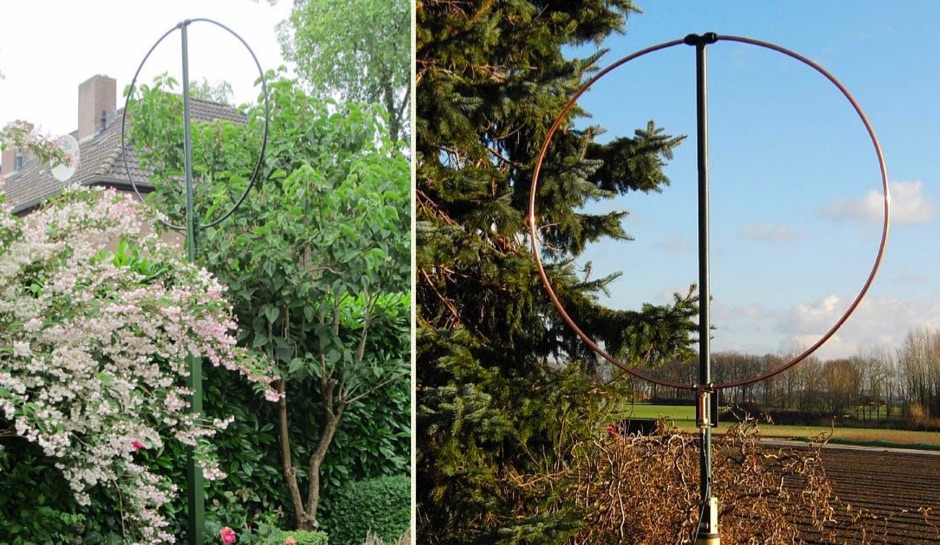 A shielded broadband (~200 MHz) active loop antenna offers more quiet and relatively less interference reception.
 -
 Documents the construction of a **VHF/UHF** antenna addition for the Buddipole HF antenna system, leveraging the existing Versa-Tee component. The project details the fabrication of a custom antenna mount from angle aluminum, including specific drilling and tapping for 3/16"-24 bolts, and the creation of radials from Simpson Strong Tie Insulation Supports. It specifies radial lengths for 70 centimeters (6 inches from the center stud) and 2 meters (19 1/4 inches), noting the use of wire nuts for safety. The resource outlines the construction of a mast from 1/2" ID PVC conduit, connected with 3/8"-24 connecting nuts and bolts, mirroring the Buddipole's modular design. It describes the integration of a mobile dual-band antenna with a 3/8"-24 mounting stud and the custom coax setup with BNC and **PL-259** connectors. Field testing with an FT-817ND and a separate dual-band SWR meter confirmed good SWR on both 2 meters and the 440-450 MHz section of 70 centimeters, with positive reception reports during Field Day activities. Further, the article describes the creation of a custom carrying solution, including a 22-inch tripod bag and a fabric roll-up, to emulate the portability of the original Buddipole system.
 -
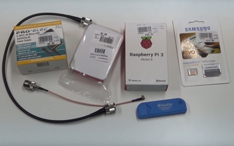 How to receive automatically NOAA wather satellite images with a Raspberry Pi and a RTL SDR. This project requires a Raspberry Pi 3 Model B a common NooElec SDR Dongle and a QFH Antenna in the attic. Article explains how to setup and configure software but no instructions on antenna.
 -
 The Kenwood TS-870S HF transceiver features two state-of-the-art 24-bit 20 MIPS DSP chips, providing over 100dB out-of-passband attenuation and CW bandwidth adjustable to 50 Hz. It operates across 160-10 meters with 100 watts output, incorporating digital filtering, a beat canceller, and 100 memory channels. The radio also includes a transmit equalizer, RX antenna input, and a K1 Logic Keyer, enhancing signal processing and operational flexibility for amateur radio operators. Advanced capabilities include IF stage DSP, dual noise reduction, and an auto notch filter, all contributing to superior signal reception and clarity. The TS-870S offers a variable AGC, voice equalizer, and an RS-232C port for computer control, with Windows™ software supplied. Its built-in automatic antenna tuner functions on all bands for both transmit and receive modes, streamlining station setup and operation. Available accessories such as the DRU-3A digital recording unit, SO-2 high stability crystal oscillator, and VS-2 voice synthesizer option further extend the transceiver's utility. The unit requires 13.8 VDC at 20.5 Amps and is supplied with an MC-43S hand microphone, making it a comprehensive station component.
 -
 PSK Reporter provides a real-time visualization of amateur radio digital mode reception reports, aggregating data from a global network of monitoring stations. This platform is particularly useful for operators utilizing modes such as FT8, FT4, and PSK, allowing them to observe signal propagation paths and assess their station's reach. The interactive maps display reception reports, enabling hams to analyze band conditions and optimize antenna performance for various frequencies and times of day, aiding in understanding ionospheric conditions. Operators can filter reports by callsign, band, mode, and time, gaining insights into specific propagation events or evaluating the effectiveness of their transmit setup. The data collected helps in predicting optimal operating windows for DX contacts across various digital modes. Philip Gladstone is the contact person for comments and discussions regarding the system.
 -
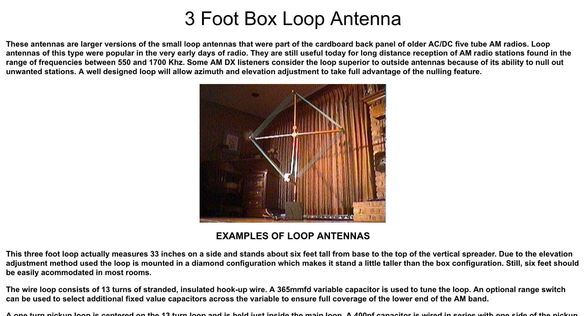 These antennas are larger versions of the small loop antennas that were part of the cardboard back panel of older AC/DC five tube AM radios. Loop antennas of this type were popular in the very early days of radio. They are still useful today for long distance reception of AM radio stations
 -
 Designing and constructing a two-element receiving loop antenna array for HF operation involves specific considerations for achieving high directivity and noise reduction. This resource details a homebrew system comprising two 30-inch diamond-shaped loops, spaced 20 feet apart, which are fed through mast-mounted preamplifiers and passive signal combiners. The operational principle relies on adjusting phase delays between elements via precise _Belden 8241_ coaxial cable lengths, optimized for specific bands from 160m to 20m. Performance data, derived from _EZ-NEC_ modeling, illustrates consistent 90° azimuth-plane beamwidth and low take-off angles across the target bands, with _Receiving Directivity Factor_ (RDF) values comparable to a 300-foot Beverage antenna. The article presents detailed elevation and azimuth plots for 20m, 30m, 40m, 80m, and 160m, demonstrating the array's ability to provide strong response at low DX angles while also supporting _NVIS_ signals. Key components like the _DX Engineering RPA-1_ preamplifier and _DXE RSC-2_ signal combiner are discussed, alongside the importance of impedance matching to preserve antenna patterns. The construction emphasizes self-contained elements that do not require ground radials, offering a compact solution suitable for suburban environments and stealth installations, with a focus on optimizing receive performance independently from transmit antennas.
 -
 An experimental antenna for HF reception. It consists of a single loop element mounted on the ground. It is stealthy, small, and quiet. EZ-NEC plots and on-air test results are included.
 -
 The video delves into the fascinating science behind antennas, which are crucial for receiving and transmitting electromagnetic waves. It explains how antennas convert electric signals into electromagnetic waves for transmission, and how they operate through the oscillation of positive and negative charges in dipole arrangements. Practical antenna implementations, such as dipole antennas for TV reception and Yagi-Uda antennas with reflectors and directors, are also discussed alongside modern dish TV antennas with parabolic reflectors for signal processing. It's a comprehensive overview of how antennas work and their significance in communication technology.
 -
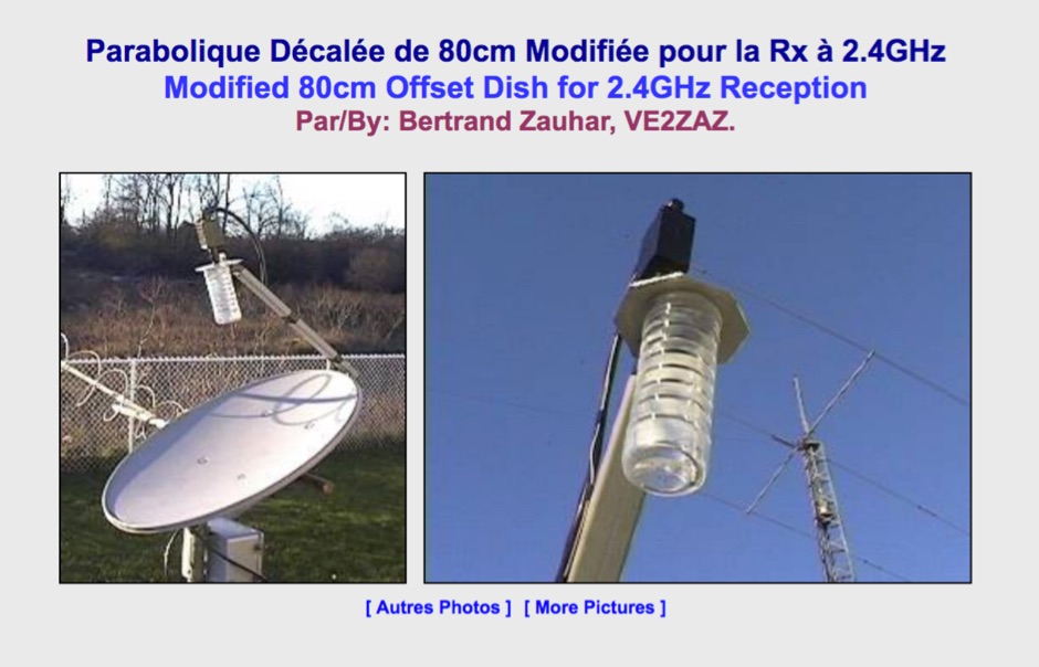 Modified 80cm Offset Dish for 2.4 GHz Satellite Reception. This 50-ohm impedance antenna allows, when connected to 2.4GHz preamplifier and downconverter, to receive Amateur satellites with 2.4GHz transponders such as AO-40.
 -
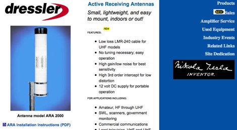 Active Receiving Antennas, designed for reception of shortwave, mediumwave and longwave signals and VHF/UHF signals
 -
 Documents the operational experiences and technical insights of amateur radio station VA3STL, offering a firsthand account of various on-air activities and equipment. The blog features a detailed narrative of a **QRP transatlantic QSO** on 12m SSB, achieving a 55 report with 10W to a mobile station in Italy using a homebrew 90ft doublet antenna. It also introduces the _Ten-Tec 539_ QRP HF transceiver, a 10W output rig covering 80m through 10m, designed for portable operations and featuring DSP and dual VFOs. The resource also delves into historical radio technology, specifically the "Gibson Girl" survival radio, an emergency transmitter operating on 500kHz (and later 8280/8364 kHz) with a hand-cranked generator and kite-deployed antenna. This section explores its origins from German designs and its use during World War II, including its distinctive curved shape for ergonomic hand-cranking. Further historical content includes a visit to Signal Hill in St. John's, Newfoundland, commemorating Marconi's reception of the first transatlantic radio signal in 1901. The post describes the Cabot Tower exhibit and the VO1AA station, highlighting the site's significance despite the thick fog during the visit. It also showcases a homebrewed _Marconi-style straight key_ by WB9LPU, crafted to celebrate the centenary of Marconi's achievement.
 -
 How to receive NOAA weather satellite with a home made QFH Antenna. This project includes some easy and efficient notch filters to suppress noise from FM frequencies
 -
 On December 12, 1901, Guglielmo Marconi successfully received the first transatlantic wireless communication, a Morse code "S" (three dots), at 04:30 GMT. This article details the setup for this groundbreaking experiment, noting Marconi's receiver in St. John’s, Newfoundland, Canada, utilized a _coherer_ and an antenna elevated by balloons and kites. The transmitting station at Poldhu, Cornwall, England, featured twenty-four 200-foot ships' masts and a 25-kilowatt alternator. The resource explains how this contact disproved contemporary beliefs about radio wave limitations due to Earth's curvature, later understood through _ionospheric propagation_. It frames Marconi's achievement as the "very first DX" in amateur radio terms, defining DX as telegraphic shorthand for distance and _DXing_ as the hobby of receiving distant signals. The article also provides external links for further reading on Marconi's experiments and the science behind transatlantic radio signal reception.
 -
 Introduction to homebrewing antenna, for AM FM band reception
 -
 A Dutch website dedicated to weather satellite reception with many documents related to antennas, software and techniques on receiving signals from weather satellites.
 -
 A Shielded Low Frequency Loop Antenna, allows Simultaneous Transmission and Reception at the Same Site.
 -
 The BikeLoop antenna project details the construction of a double magnetic loop antenna optimized for VLF frequencies, specifically around 136 kHz. This innovative design incorporates two orthogonal loops, which significantly enhance reception capabilities. Key construction hints include utilizing lightweight bicycle rims for the antenna structure, making it easy to transport and set up in various locations. The document provides valuable mathematical and electrical insights into the antenna's performance, alongside practical reception tests conducted in the Italian Alps, showcasing its effectiveness in capturing various VLF signals, including Sferics and FSK transmissions. Proper setup is crucial for optimal performance. The project emphasizes the importance of grounding and avoiding interference from nearby electrical sources. The reception tests revealed the antenna's ability to capture a range of signals, demonstrating its practical application for enthusiasts interested in VLF reception and antenna experimentation. Overall, the BikeLoop serves as an excellent starting point for those looking to explore the world of VLF frequencies and enhance their antenna-building skills.
 -
 The DIY 137 MHz WX SAT V-dipole antenna project details the construction of a specialized antenna for receiving weather satellite transmissions. It provides specific dimensions for the dipole elements, designed for optimal reception around the 137 MHz band, which is commonly used by NOAA and Meteor weather satellites. The resource outlines the materials required, such as aluminum tubing for elements and PVC for the support structure, along with the necessary coaxial cable and connectors. The article presents a clear, step-by-step assembly process, including how to form the V-shape and connect the feedline. It emphasizes practical considerations for mounting and weatherproofing the antenna for outdoor deployment. The design focuses on simplicity and effectiveness for amateur radio operators interested in satellite imagery. Key aspects include the precise angle of the V-dipole and the lengths of the radiating elements, which are critical for achieving the desired circular polarization response for satellite signals. The resource includes photographic documentation of the construction phases and the final mounted antenna.
 -
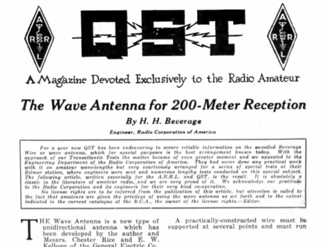 A QST Article published in November 1922 is about the origin of Beverage antennas, an unidirectional antenna type that was discovered and experimented for the first time in that period. This article is the introduction to beverage antenna theory, by the homonimous autho H. H. Beverage.
 -
 Discovering a solution for limited space, the inverted L HF antenna emerges as a stellar performer. Half the size of a dipole, it ensures optimal installation in restricted areas, maintaining superb transmission (TX) and reception (RX) characteristics. Spectrum Communications' multi-band version, featuring traps, proves even more space-friendly without compromising performance. A fiberglass pole offers sturdy support, while proper grounding, an RF choke, and occasional tuning contribute to a high-performing and reliable antenna system.
 -
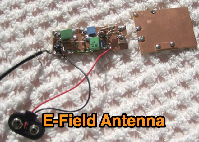 A small active voltage probe antenna to aid reception on the LF bands
 -
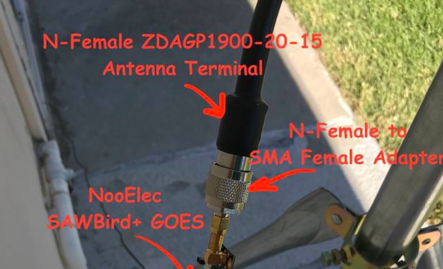 Receiving **GOES-16** and **GOES-17** weather satellite imagery requires a specific hardware and software configuration, detailed in this practical guide. The author outlines the necessary components, including a Raspberry Pi, an RTL-SDR dongle, a suitable LNA with SAW filter for 1.69 GHz, and a parabolic grid antenna. This setup enables direct reception of high-resolution weather data, a fascinating aspect of amateur radio satellite operations. The installation process begins with preparing the Raspberry Pi, followed by updating the system and installing essential dependencies like `git`, `build-essential`, and `cmake`. A critical step involves compiling and installing `librtlsdr` from source, ensuring proper driver setup and blacklisting conflicting DVB drivers. The guide then walks through testing the RTL-SDR dongle to confirm device recognition and troubleshoot common issues like USB power or driver installation problems. Finally, the instructions cover cloning and building `goestools`, a software suite essential for processing the satellite signals. This compilation, while time-consuming on a Raspberry Pi, is crucial for decoding the raw data into usable imagery. The guide concludes with the initial steps for creating the `goesrecv.conf` configuration file, preparing the system for active satellite reception.
 -
 The video showcases the setup of a 300 MHz oscillator, a 100W radiofrequency amplifier, and a dipole antenna for transmitting radio waves, leading to the fluorescence of a nearby light bulb. It demonstrates the presence of standing waves on the dipole antenna and how intensity varies along its length. Additionally, the usage of a copper pipe as a receiving antenna is explored, showing changes in intensity depending on alignment and proximity to the transmitter. Finally, a B field antenna sensitive to magnetic fields is introduced, revealing brightness variations in different orientations. The video offers insightful observations on radio wave transmission and reception phenomena.
 -
 A simple superheterodyne receiver (3.5–30 MHz) for amateur radio achieves stable SSB-CW reception using modern BJTs, an AD831 mixer, a 6-pole quartz filter, and Seiler oscillators. Designed with high IF (4.5 MHz), compact AM-FM variable capacitors, and modular resonant circuits, it ensures selectivity, image rejection, and stable tuning. Built in a copper-lined wooden case, it features practical assembly techniques but lacks advanced features like AGC or S-meter. Effective on basic antennas, it achieves global reception.
 -
 a 20M quarter-wave vertical antenna with a 6m telescopic mast, 1:1 balun, and spiral-wound driven element. Designed for QRP at 14.285 MHz, the antenna’s performance exceeded expectations, delivering low SWR and surprisingly quiet reception. Initial testing yielded successful contacts with European stations and EC1KR, showcasing its effectiveness. Compact and easy to deploy, the antenna promises to be an excellent portable solution for future hilltop operations.
 -
 Learn about the practical design and construction of Yagi antennas for ham radio operators. This post explores the benefits of Yagi antennas in receiving and transmitting RF signals, concentrating signal energy in one direction for long-distance communication. Discover the theory behind Yagi antennae, the importance of element size and spacing, and the resources available for sizing and construction. Whether you're interested in OTA television or amateur radio communication, understanding Yagi antenna design can enhance your signal reception and transmission capabilities.
 -
 Learn how to design and analyze a folded trifilar antenna for the 80-meter band. Based on a description from RAF antennas between 1940 and 1970, this article provides step-by-step guidance on modeling the antenna, calculating resonance frequency, adjusting dimensions, and verifying performance. Perfect for hams looking to improve their antenna setup for better transmission and reception on the 80M band.
 -
 The HF Beacon Tracker is an advanced interactive tool designed for DXers and ham radio opoerators in general to monitor active beacons operating below 14 MHz. Built upon a high-fidelity 3D Earth globe, the application provides a spatial perspective on signal paths by integrating real-time environmental data with a comprehensive beacon database curated by Mirek OK1DUB. Beacons are plotted using precise Maidenhead locators and feature a real-time day/night terminator overlay to help operators identify Gray Line propagation opportunities. With a single click, users can calculate the exact distance from their own QTH to any beacon, visualized via an animated Great-Circle Path arc on the globe surface. To enhance its diagnostic capabilities, the tool seamlessly integrates with PSK Reporter, allowing users to right-click CW beacons to instantly fetch current reception reports and signal strength data. The interface is fully optimized with a mobile-responsive design, smooth globe rotation, and togglable Dark/Light themes suitable for any shack environment. Whether you are performing antenna gain tests, conducting ionospheric research, or simply hunting for band openings, the HF Beacon Tracker transforms raw database information into an intuitive, visual diagnostic suite. It serves as an essential asset for any operator looking to master HF band conditions.
 -
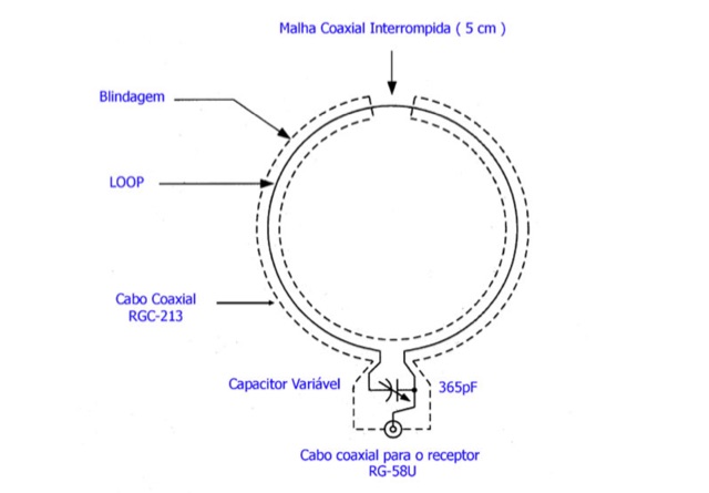 This page is a project for a small loop antenna for reception of short wave broadcasting. It is in Portuguese and contains pictures and schematics to build your own antenna
 -
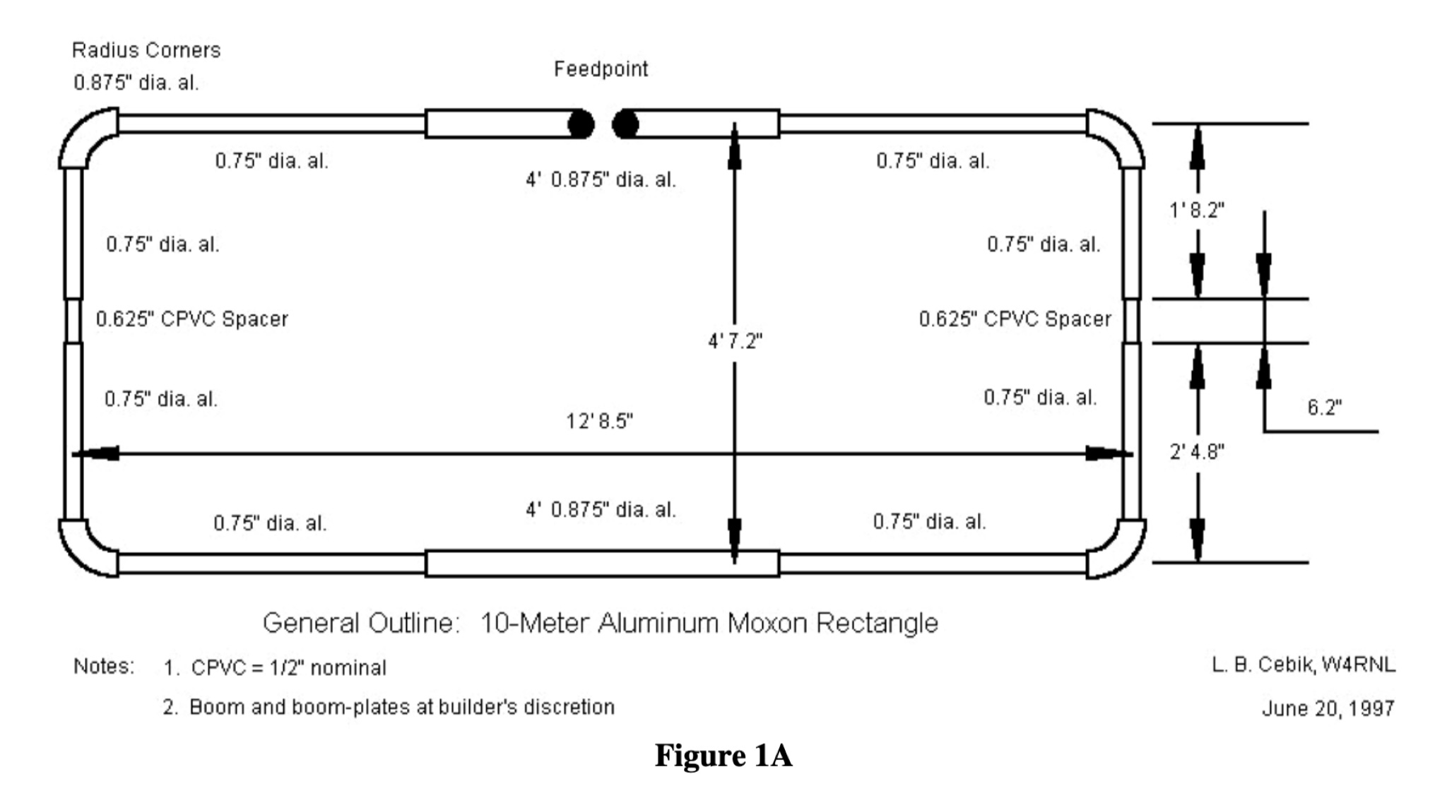 This PDF document provides a comprehensive guide on building and using the Moxon Rectangle antenna design for hams. It covers the construction, setup, and tuning of this directional antenna, offering practical advice and tips for amateur radio operators looking to improve their signal reception and transmission capabilities. The guide includes diagrams, measurements, and step-by-step instructions to help hams successfully implement the Moxon Rectangle design for their radio communication needs.
 -
 This article describes the phases for the construction of a Yagi antenna. The calculations of the parameters are made using 4NEC2 software. This type of antenna is used for transmissions and receptions of electromagnetic waves. The project shown here refers to the frequency of 433.92 MHz.
 -
 This project focuses on testing and comparing various antennas for receiving ADS-B (Automatic Dependent Surveillance-Broadcast) signals, utilizing software tools like RTL1090 and Virtual Radar with an RTL-SDR dongle. The goal is to evaluate the reception range ("ReceiverRange") and performance of different antenna types when tracking aircraft signals, particularly around the Amersfoort area. The project includes a comprehensive photo album documenting the antenna designs and setup processes, serving as a valuable resource for enthusiasts building ADS-B reception systems
 -
 The document details the construction and performance of a rotatable flag antenna designed for a small lot. The 7x14 feet flag, built with fiberglass poles and an aluminum hub, shows improved reception compared to the author's previous transmit antenna. Key components include a conventional transformer for impedance matching and a variable resistance termination system to optimize performance. Despite challenges like nearby objects affecting signal patterns, the antenna consistently provides better signal-to-noise ratios, making it a valuable addition for low-band listening in suburban areas.
 -
 This project explores the construction and performance of an Alford Loop antenna as an alternative to a round loop. The Alford Loop, symmetrically fed at opposite corners, behaves like a small loop despite its larger size. Built using PVC pipes and secured with tire wraps, the antenna integrates an LZ1AQ active amplifier for optimal performance. With deep nulls in its horizontal radiation pattern and improved resonance characteristics, this design has significantly outperformed previous active antennas in reception quality.
 -
 This study details a reception comparison between vertical and horizontal active loop antennas, specifically two identical _Wellgood active loop antennas_, on various HF bands. The experiment, conducted in a densely populated QRM-prone area, monitored FT8 signals over a 24-hour period using two identical receivers. The methodology involved direct comparison of signal reception across the HF spectrum, aiming to identify performance differences based on antenna orientation. The results indicate that vertical loops demonstrated superior performance on higher bands (10m, 15m, 20m), while horizontal loops excelled on lower bands (30m, 40m, 160m), particularly for receiving long-distance (DX) signals. The horizontal loop's advantage on lower bands is attributed to potentially better low-angle performance and reduced sensitivity to man-made noise, yielding a **2-3 S-unit** improvement on 160m. The study provides practical insights for optimizing antenna placement in challenging urban environments, noting that the horizontal loop consistently showed a **10-15 dB** signal-to-noise ratio improvement on lower bands.
 -
 The article describes the construction of a Lindenblad antenna, which is well-suited for receiving signals from low-orbiting weather satellites. The key points are: The Lindenblad antenna has an omnidirectional horizontal radiation pattern and is optimized for low to medium elevation angles, making it ideal for tracking passing satellites near the horizon. It is designed to receive circular polarization, which is common for weather satellite signals. The antenna is constructed using 4 folded dipole elements arranged on a cross-shaped frame. The necessary materials include a plastic junction box, PVC tubing, and aluminum rods to form the dipole elements. The article provides detailed instructions for preparing the components, assembling the dipoles, and connecting the feed lines to create the complete antenna. The completed antenna can be mounted on a vertical support, with the dipole elements angled at 30 degrees from horizontal, to optimize reception of the passing satellites. The author notes that the design was originally published in a now-defunct magazine, Meteo Satellite Inf", in 1993
 -
 This DIY guide details constructing a 5-element Yagi antenna for VHF frequencies. Yagi antennas offer directional signal transmission/reception compared to omnidirectional ones. The guide covers material selection (aluminum, screws, etc.), design using software or formulas, and step-by-step assembly including cutting elements, drilling holes, and attaching the coaxial cable. While calculations are provided for a 146 MHz design, adjustments are necessary for different frequencies. Safety precautions and potential result variations are emphasized.
 -
 This page provides detailed instructions on refining an end-fed vertical dipole antenna for ham radio operators looking to improve their signal reception and transmission. The content offers practical tips and techniques for optimizing the performance of this specific type of antenna. The page is useful for hams who are interested in experimenting with different antenna designs and configurations to enhance their overall radio communication experience.
 -
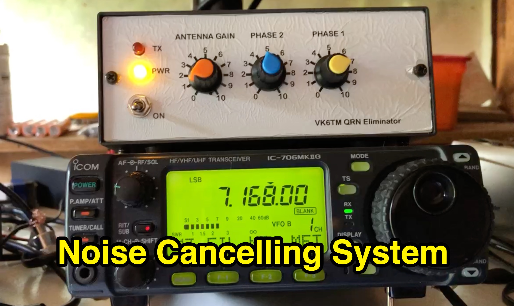 Learn how to improve reception on the hf bands by setting up a noise cancelling system that nulls out local interference. This article describes a system using a 'Main Station Antenna' to receive a wanted signal and associated QRM, and an 'Auxiliary Antenna' to pick up unwanted interference. Gain and phasing controls are used to reduce/remove interference, leaving only the wanted signal. Tips are provided based on the author's personal experience, applicable to commercial noise cancelling products, kit form, or homebrew setups. Discover the importance of configuring the 'Auxiliary Antenna' to optimize your system and improve readability of wanted stations.
 -
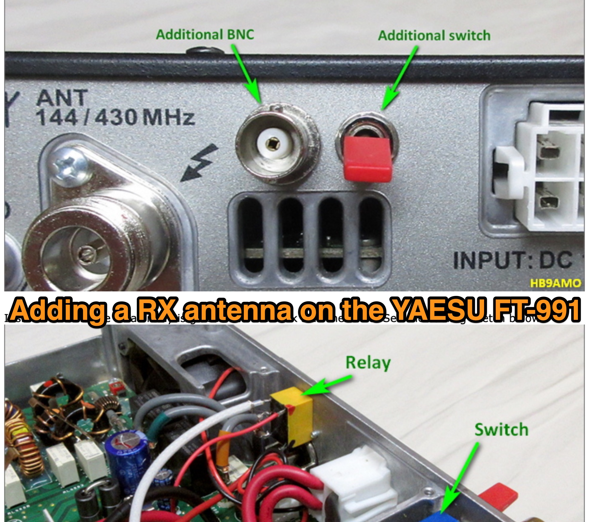 The FT-991 is a nice small size and lightweight radio, it is perfect for portable operations. It can be carried along with a laptop computer as hand luggage in airplane. The weak point of this radio, is it does not have a separate RX antenna capability. Therefore i decided to add this feature. On the back side of the radio a BNC connector is added to connect the RX antenna and a switch is fitted to select between RX antenna or main antenna.
 -
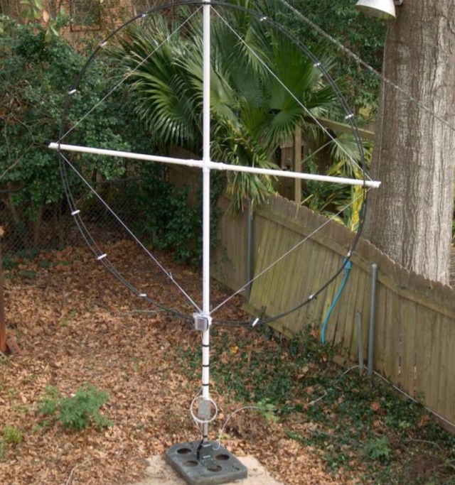
 Learn how to build a portable receiving antenna for the 160 meter band. This guide provides detailed instructions on constructing a loop antenna using a coaxial cable RG-316 with SMA connectors. The antenna weighs 1.7 kg and has dimensions of 2m in height and 1.892m in width. The wooden frame consists of four 0.945m long pieces and two 1m long pieces. Perfect for hams looking to enhance their 160m band reception during travel or portable operations.
 -
 The Slim Jim VHF antenna, originally designed by G2BCX, is a folded half-wave dipole fed by a quarter-wave matching section. This version, built from a recycled professional aluminum dipole, demonstrates that various materials—such as copper, brass, or twin-lead—can be used. The article details the antenna’s construction, required materials, and tuning process, emphasizing mechanical stability and ease of assembly. With proper adjustment of the feed point, it provides excellent SWR across the band. Its durability and simplicity make it a practical and efficient VHF antenna solution.
 -
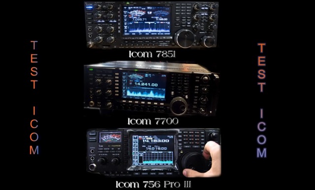 Reception test comparison between IC 756 pro III, IC 7700 and the last jewel by ICOM IC 7851
 -
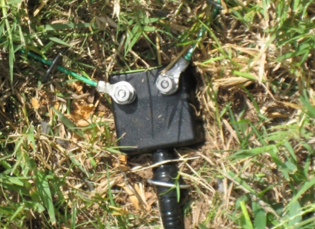
 This page provides information about building a Beverage antenna for hams. The article discusses using a 60m wire on the ground to create an effective antenna for amateur radio operators. Learn how to set up and optimize this type of antenna for better reception and communication. This describes a low-noise receiving Beverage antenna setup for low bands, using a N30 cup core transformer for 1:4 impedance matching (likely 50:200 Ohm), RG-58 feedline with heavy common-mode choking, and conduit for wire burial.