Search results
Query: transmit freq
Links: 107 | Categories: 2
-
 Transferring Radio Frequency Energy from Your Transmitter to Your Antenna by Don Keith N4KC
 -
 A cavity filter, often a critical component in _duplexer_ designs, functions as a sharply tuned resonant circuit, allowing only specific frequencies to pass while attenuating others. These filters are essential for maintaining signal integrity in environments where multiple transmitters and receivers operate simultaneously on closely spaced frequencies, such as in repeater stations. The article details how these filters, sometimes referred to as _notch filters_, achieve high Q factors, which are crucial for their performance. Understanding the principles of cavity filters is fundamental for any amateur radio operator involved in repeater operation or designing custom RF front-ends. The discussion covers the basic circuitry and operational characteristics that enable these devices to provide significant isolation, often achieving **-80 dB** or more between transmit and receive paths. This level of isolation is vital for preventing receiver desensitization and intermodulation distortion. Properly tuned cavity filters ensure that a repeater can transmit and receive simultaneously on different frequencies without self-interference, a common challenge in VHF/UHF operations.
 -
 The 2200-meter band (135.7-137.8 kHz) presents unique challenges for amateur radio operators due to its narrow 2.1 kHz bandwidth, low signal levels, and high noise. W1TAG explores various transmission modes suited for this demanding environment, highlighting that traditional voice modes like SSB and AM are impractical. Plain old CW serves as the baseline, demonstrating effectiveness across different modes, though signal-to-noise ratio (SNR) significantly limits practical speeds. The article notes that reducing CW speed below 5 WPM can improve copy, especially with computer-aided spectrum analysis software capable of decoding signals too weak for human ear reception. QRSS, or "CW sent slowly enough that speeds are best expressed in seconds per dot," is a key mode for LF work, with examples ranging from 3 seconds/dot to extreme 240 seconds/dot transmissions. _Argo_ by I2PHD is mentioned as a simple program for QRSS, enabling reception of signals like BRO, a Part 15 beacon, at a distance of **1100 miles**. Other modes discussed include Dual Frequency CW (DFCW), which uses frequency shifts to distinguish dots and dashes, and Binary Phase Shift Keying (BPSK), a phase modulation technique employing 0 to 180-degree phase flips. WOLF (Weak-signal Operation on Low Frequency), a specialized BPSK form by KK7KA, encodes 15-character messages into 960-bit packages, taking 96 seconds to transmit, and has demonstrated successful reception over **672 seconds** for a message from a 1-watt beacon. Further modes include PSK, FSK variations like JASON and MSK, and graphical modes such as Hellschreiber and Chirped Hell. The article concludes with a practical chart comparing the time required to send a simple message like "WD2XES FN42CH " across these diverse LF modes, offering valuable insights for operators planning contacts on the low bands.
 -
 Amateur radio repeaters extend communication range for mobile and remote stations by retransmitting signals on a different frequency, often for emergency communications. The resource details various repeater bands, noting that 2 meters and 70 cm are primary for activity, with 10-meter repeaters offering potential national and overseas coverage. It specifies **18 channels** on 6 meters and **31 channels** on 2 meters, along with a new 70 cm offset of _7 MHz_ adopted in 2015. The content explains how repeaters can be linked via dedicated transmitters/receivers, landlines, or Internet VoIP systems like _IRLP_ and Echolink, enabling global connections. It also describes simplex gateways for multi-band operation and the use of CTCSS subaudible tones for access control and interference mitigation. The document highlights specialized repeaters for modes beyond voice, such as SSTV and ATV, particularly on 70cm and higher bands. Operational guidelines for efficient and courteous repeater use are referenced, along with links to Australian repeater listings and band plans.
 -
 The Doppler Effect allows the distance between a satellite transmitting from space and a radio receiver on the ground to be measured by observing how the frequency received from the satellite transmitter changes as the satellite approaches, passes overhead, and moves away.
 -
 High Frequency Expermental Beacon "WV". The Beacon operates on the frequency of 13.55567mhz. This Beacon is very low power. It operates under Part 15 of the FCC Rules and Regulations. It transmits with only 1.5 milliwatts of power
 -
 Amateur Television (ATV) operations involve transmitting and receiving live or recorded video and audio signals over amateur radio frequencies. Unlike narrow-band modes, ATV utilizes a wider bandwidth to convey video information, often requiring specialized transceivers, antennas, and signal processing equipment. This mode allows hams to share visual content, demonstrate projects, or conduct video conferences, typically on VHF, UHF, and microwave bands due to the bandwidth requirements. The SwissATV resource focuses on the technical aspects and community engagement surrounding ATV within Switzerland. It covers topics relevant to setting up ATV stations, understanding signal propagation at higher frequencies, and participating in local ATV activities. The site serves as a central point for Swiss ATV operators to exchange knowledge and coordinate transmissions, fostering the growth of this specialized amateur radio mode.
 -
 Sixty-meter repeaters typically use a 1 MHz frequency separation between input and output, while 2-meter repeaters commonly employ a **600 kHz** split and 70-centimeter repeaters use a **5 MHz** offset. This article details the fundamental technical principles of amateur voice repeaters, explaining how they extend VHF/UHF communication range by receiving on one frequency and simultaneously retransmitting on another. It covers essential components such as receivers, transmitters, filters, and antennas, often situated on elevated locations for optimal coverage. The resource delves into the critical challenge of _desensing_—where the repeater's strong transmit signal overpowers its own receiver—and the engineering solutions employed, including antenna separation and the use of high-Q cavity filters. It also explores various control and timing systems, from basic squelch activation to more sophisticated microcontroller-based boards that manage functions like voice identification, time-out timers, and fault protection. Different access methods are discussed, including open access, toneburst, CTCSS subtone, and DTMF, each offering distinct advantages for managing repeater usage and mitigating interference. Furthermore, the article examines repeater linking, both conventional RF methods and modern internet-based solutions, highlighting how linking expands coverage and promotes activity across multiple repeaters or bands. It introduces less common repeater types such as 'parrot' repeaters, which use a single frequency and digital voice recording, and linear translators, capable of relaying multiple signals and modes simultaneously across different bands, often found in amateur satellites.
 -
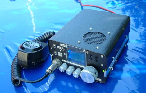 This article describes the construction of a high performance transmitter and receiver for SSB (voice) communication covering the 14MHz (20 meters) high frequency amateur radio band with output range 15 to 20 watts and a top audio sound quality both on transmit and receive.
 -
 Developing operational amateur radio equipment for the 134 GHz band presents significant technical challenges, particularly in frequency generation and stability. This resource details the construction of a 134 GHz system, outlining its architecture with separate transmit (Tx) and receive (Rx) modules, each employing a local oscillator (LO) and RF head units. The system utilizes a dual Flann 50 GHz lens-type horn antenna configuration for optimal signal coupling. The transmit path incorporates an LMX2541 synthesizer chip operating at approximately 2.8 GHz, referenced by a 10 MHz double-oven Morion OCXO for exceptional stability. This signal is multiplied through a series of stages (X4, then X2) to generate a 22.4 GHz signal, which subsequently drives a dual series diode multiplier to produce the final X6 signal for 134 GHz operation. The receive side features an anti-parallel diode mixer coupled to a 144 MHz transceiver via a preamplifier, ensuring effective downconversion. Operational mode is CW, achieved by keying a multiplier stage. The project includes images of the Tx and Rx head units and describes a successful 3.5 km test with G8ACE, demonstrating stable signal tones due to PLLs locked to OCXOs at both ends, confirming the system's robust performance.
 -
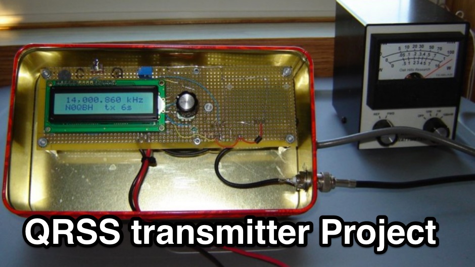 The N0QBH QRSS project page, a couple of projects using available kits for improved frequency and timing stability. A configurable DDS VFO 100mW transmitter with LCD display and a modified Hans Sommers 40m 100mW transmitter
 -

-
 Station QRP presents various **circuit diagrams** for constructing low-power AM vacuum tube shortwave transmitters, catering to enthusiasts interested in vintage radio technology. The resource details schematics ranging from simple to more complex designs, enabling hams to build their own QRP AM transmitters for operation on frequencies like 6.925 kHz AM. It emphasizes the use of vacuum tubes, providing a technical foundation for understanding and replicating classic shortwave broadcasting methods. The content is geared towards those who enjoy the hands-on aspect of electronics and the unique characteristics of tube-based RF circuits. Building these transmitters allows operators to experience the nostalgia of early shortwave radio, with the site specifically mentioning a pioneer station on 6.925 kHz AM. The designs facilitate experimentation with low-power AM transmission, offering practical application for homebrew projects. The focus on QRP (low power) operation aligns with a segment of the amateur radio community that values efficiency and minimalist setups, providing a distinct alternative to modern solid-state transceivers.
 -
 Low-frequency (LF) radio time signals, operating primarily in the 40–80 kHz range, are broadcast by national physics laboratories for precise clock synchronization. Transmitters like **JJY** (40 kHz, 50 kW; 60 kHz, 50 kW), RTZ (50 kHz, 10 kW ERP), MSF (60 kHz, 15 kW ERP), WWVB (60 kHz, 50 kW ERP), RBU (66.66 kHz, 10 kW), and DCF77 (77.5 kHz, 50 kW) cover vast geographic areas, often several hundred to thousands of kilometers. LF signals offer distinct propagation advantages over higher-band transmissions such as GPS. Their long wavelengths (3–6 km) enable effective diffraction around obstacles like mountains and buildings. The ionosphere and ground act as a waveguide, eliminating the need for line-of-sight and allowing a single powerful station to cover extensive regions. Ground wave propagation minimizes ionospheric variability effects on transmission delay, and signals penetrate most building walls effectively. Robust and low-cost receivers, often priced at 20–30 USD/EUR, are widely used in radio clocks. These receivers typically comprise a tuned ferrite core antenna, a receiver IC (e.g., Atmel T4227, U4223B, MAS1016) for amplification and AM detection, and a microcontroller for decoding the time signal and phase-locking a local clock. Specific components for DCF77, MSF, and WWVB are readily available from vendors like HKW Elektronik and Ultralink.
 -
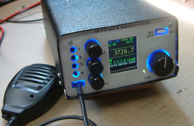 Gimme Five reloaded, a compact 5 band QRP SSB transceiver in SMD technology. This unit covers 5 bands within the amateur radio spectrum (3.5, 7, 14, 21 and 28 MHz). Receiver is a single conversion unit with an interfrequency of 9 MHz. Transmitter uses 5 stages and has got a power level of 10 watts PEP output.
 -
 The Baofeng UV-5R handheld transceiver, introduced around 2012, operates across the 2-meter (144-148 MHz) and 70-centimeter (420-450 MHz) amateur bands, offering dual-band receive and transmit capabilities. This review provides an early assessment of the radio's form factor, user interface, and general performance, noting its compact size and the inclusion of a **VFO/Memory mode** button for frequency management. The device supports both FM and narrow FM modes, with a reported power output of 4 watts on VHF and 3 watts on UHF, making it suitable for local simplex and repeater operations. Key features discussed include its 128-channel memory capacity, a built-in VOX function, and a **DTMF keypad** for tone dialing and repeater access. The review highlights the radio's ability to scan frequencies and memories, along with a dual-watch function allowing simultaneous monitoring of two frequencies. Battery life is addressed, with the standard 1800 mAh Li-ion pack providing several hours of operation depending on transmit usage. Initial impressions cover the radio's construction and the clarity of its LCD display, which shows both A and B band frequencies.
 -
 rpitx is a general radio frequency transmitter for Raspberry Pi which doesn't require any other hardware unless filter to avoid intererence. It can handle frequencies from 5 KHz up to 1500 MHz.
 -
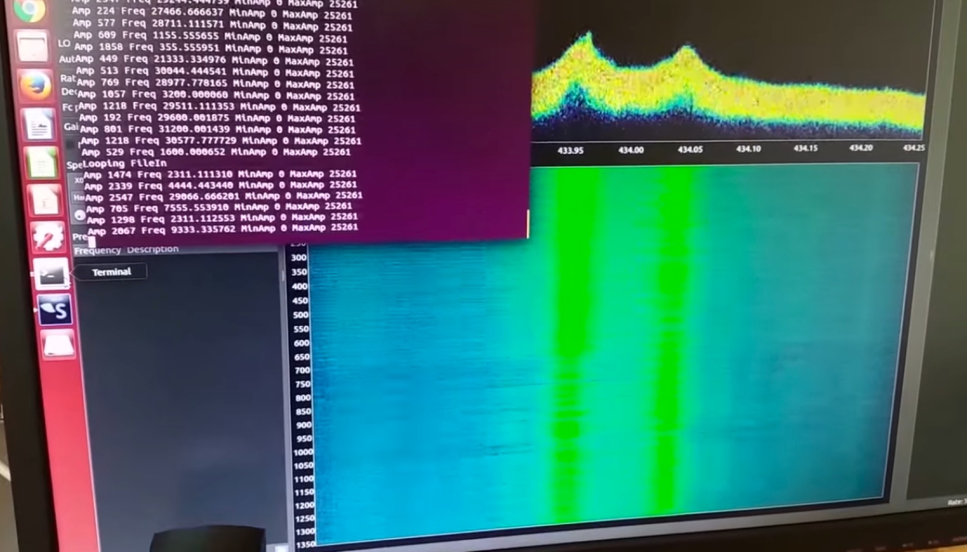
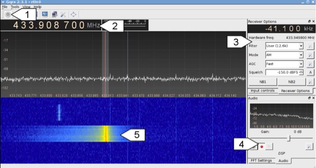 Analyzing 433 MHz radio signals from common wireless devices, such as temperature sensors and remote controls, involves understanding **On-Off Keying (OOK)** modulation. This resource details the process of capturing these signals using a Software Defined Radio (SDR) like Gqrx and then visually inspecting the captured audio data in a sound editor such as Audacity. It differentiates between **Pulse Width Modulation (PWM)** and Pulse Position Modulation (PPM) encoding schemes, illustrating how to identify and decode binary data by eye based on pulse and gap durations. The article provides a step-by-step walkthrough for decoding a wireless thermometer's data, correlating bit patterns with known temperature, humidity, and channel values. It also demonstrates decoding an RF remote control's button presses, highlighting the constant and varying parts of the transmitted packets. The content further introduces automated decoding using tools like RTL_433, explaining its capabilities in parsing various device protocols and showing how to interpret its output, including modulation type and decoded data. Specific examples include analyzing Prologue sensor protocol specifications from RTL_433's source code and noting common operating frequencies like 433.92 MHz in Europe and 915 MHz in the US.
 -
 High Speed Multimedia (HSMM) radio, as introduced by John Champa, K8OCL, represents a significant advancement in amateur radio's digital capabilities, moving beyond traditional keyboard modes like packet radio. This initiative, driven by ARRL's Technology Task Force, focuses on developing high-speed digital radio networks capable of up to 20 megabits per second. HSMM primarily facilitates digital voice (DV) and digital video (ADV), enabling real-time video transmission from emergency scenes to an EOC without expensive ATV gear, often requiring only a laptop, a PCMCIA card, a digital camera, and a small antenna. The working group's initial efforts concentrate on cultivating microwave skills within the amateur community to build and support portable and fixed high-speed radio-based local networking, or **RLANs**. These networks prove invaluable for RACES and ARES organizations, as well as homeland security and other emergency communications. Field Day exercises and simulated emergency tests (SETs) are encouraged to hone skills in rapid site surveys and deploying broadband HSMM microwave radio networks, with examples like linking Field Day logging stations or antenna test results at the Midwest VHF-UHF Society Picnic 2003. Getting started with HSMM often involves adapting off-the-shelf **IEEE 802.11** (WiFi) equipment to comply with amateur radio regulations, typically operating in the 2.4 GHz ISM bands. While consumer WiFi gear has range limitations under Part 15 rules, proper setup under amateur regulations can extend coverage significantly, with test networks like the Hinternet achieving 5-15 mile ranges at 54 M bit/s using small mast-mounted dish antennas. Careful selection of equipment with external antenna ports, high transmit power, and low receive sensitivity is crucial, along with using low-loss coaxial cable like LMR-400 for optimal performance at these frequencies.
 -
 Amateur radio repeaters, often designated by an "R" number like _R6_ or _R5_, serve as crucial infrastructure for extending VHF/UHF communications range. This resource from Essex Ham explains the fundamental concept of a repeater, detailing how it receives on one frequency and simultaneously retransmits on another, typically with a 600 kHz offset for 2-meter repeaters. Understanding the input and output frequencies, along with the required CTCSS tone, is essential for successful access, ensuring your signal is processed and relayed across a wider service area. The article clarifies the importance of using the correct _CTCSS_ (Continuous Tone-Coded Squelch System) tone, often referred to as a sub-audible tone, to activate a specific repeater. It also touches upon the concept of _simplex_ operation versus repeater use, highlighting the benefits of repeaters for mobile and handheld transceivers. Proper operating procedures, such as listening before transmitting and keeping transmissions concise, are emphasized to maintain good amateur practice on shared repeater assets.
 -
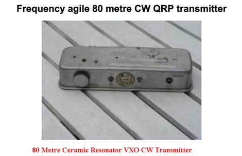 Frequency agile 80 metre CW QRP transmitter. Ceramic resonators vary in the frequency shift obtainable. The one in the prototype of this article gave 3.525 to 3.558 MHz coverage.
 -
 On the field comparison among C-Pole antenna, an EFHW vertical antenna and an Inverter V dipole antenna. Test is done using two identical WSPRLite beacons that transmit with 200mW on the WSPR frequency and analyzing spotted results.
 -
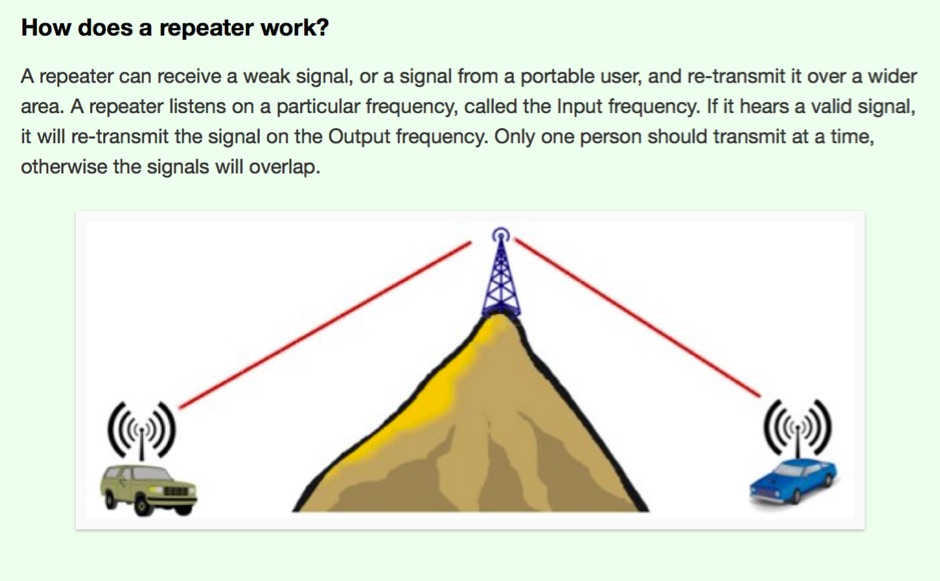
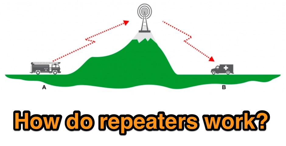 Illustrates the fundamental principles of radio repeaters, detailing their role in extending communication range beyond line-of-sight limitations. It begins by defining _simplex communication_ as a direct radio-to-radio link, effective only when no obstructions impede the signal path. The resource then introduces the concept of a repeater (or base station) strategically positioned on elevated terrain, such as a mountain, to overcome geographical barriers. The article clarifies the repeater's operational mechanism: it receives a signal on one frequency and simultaneously re-transmits it on a different frequency, enabling users on opposite sides of an obstruction to communicate. This _duplex operation_ is likened to satellite communication for VHF propagation, but with a fixed terrestrial station. Specific examples of signal paths are provided, showing how a handheld radio transmits up to the repeater, which then relays the message down to another user, effectively bypassing obstacles like hills or large buildings.
 -
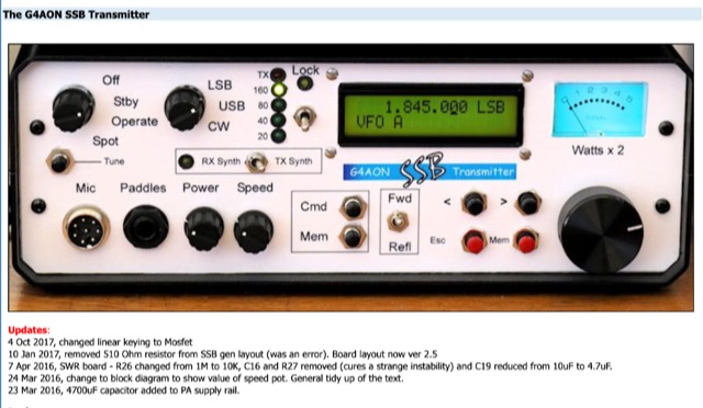 This transmitter covers the 160, 80, 40 and 20 metre bands and provides both SSB and properly generated CW. The CW side of this transmitter is not compromised and produces excellent CW. On SSB the audio has been tailored to provide a rising response to 3 KHz, with a sharp drop above that frequency. There is RF speech clipping to both provide more "punch" and to limit the peak output.
 -
 The video showcases the setup of a 300 MHz oscillator, a 100W radiofrequency amplifier, and a dipole antenna for transmitting radio waves, leading to the fluorescence of a nearby light bulb. It demonstrates the presence of standing waves on the dipole antenna and how intensity varies along its length. Additionally, the usage of a copper pipe as a receiving antenna is explored, showing changes in intensity depending on alignment and proximity to the transmitter. Finally, a B field antenna sensitive to magnetic fields is introduced, revealing brightness variations in different orientations. The video offers insightful observations on radio wave transmission and reception phenomena.
 -
 This article introduces an Arduino-based QRP CW Transceiver designed for lower HF bands. The journey begins with the Wotduino, evolving from a keyer to a multi-mode beacon. The development includes a QRP transmitter and culminates in a receiver inspired by Roy Lewallen design. The transceiver, controlled through a control bus features a signal path, modulation, filtering, and adjustable frequency settings. Despite initial testing intentions, successful QSOs on 80 and 40 meters showcase its functional capabilities.
 -
 The _G3TSO_ Mobile Antenna Page details construction and tuning methods for mobile antennas operating across **10 to 160 metres**. The content describes a Hustler-based design, optimized for RF performance and vehicle speeds, featuring centre loading. For optimal operation on various bands, the loading coil placement requires clearance from the vehicle body. Antenna resonance is critical for efficient mobile operation. A mobile antenna's base impedance may be as low as 27 ohms, requiring specific matching to achieve maximum radiation, as a minimum SWR at the transmitter does not always indicate resonance or maximum output. Tuning involves physical adjustment of antenna length to achieve resonance at the operating frequency. The _G3TSO_ page outlines a tuning procedure utilizing a low-power signal source and a field strength meter to identify maximum radiation before impedance matching. Loading coil placement, either at the base, center, or top of the antenna, influences radiation efficiency and mechanical stability for mobile installations. Centre-loaded whips, such as the Hustler design, offer a compromise between efficiency and stability, often for single-band operation. Helically wound antennas, including those for **28 MHz**, may present base impedances around 17 ohms, resulting in a 3:1 SWR at resonance. Low resistance grounding at the antenna base is also specified for optimizing performance and minimizing RFI during mobile operation. DXZone Focus: Mobile | Any | Antenna Tuning | HF
 -
 Explains the fundamental purpose of a repeater, detailing how these automated relay stations overcome distance and terrain limitations for VHF/UHF communications. It traces the historical development from early Bell Telephone Labs "relay" stations in 1922 to Art Gentry, W6MEP's, pioneering K6MYK amateur radio repeater in the mid-1950s, which remains active today. The resource clarifies the distinction between simplex and duplex operation, including the unique function of a "parrot repeater" for single-frequency recording and playback. Delving into the internal workings, the guide breaks down a repeater into its core components: the antenna system, feedline (often _Heliax_ or hardline for minimal loss), duplexer, receiver, transmitter, and controller. It emphasizes the critical role of the duplexer in preventing receiver desensitization by isolating transmit and receive signals, even with distinct frequencies. The discussion highlights the importance of high-performance, durable antennas and low-loss feedlines, citing examples of equipment installed in the 1960s and 1970s that are still in perfect working order. Operating a repeater is also covered, with an explanation of frequency offset (e.g., the 600 kHz standard for 2 meters) and the function of _CTCSS_ (PL tone) for access. It outlines standard input/output offsets for various bands, from 6 meters to 23 centimeters, while noting regional variations. The guide also touches on features like autopatch and Digital Voice Recorders (DVRs), providing a solid foundation for understanding repeater technology and usage.
 -
 This document details the construction, programming, and operation of a modular WSPR transmitter. The transmitter utilizes an ESP8266 NodeMCU, an SI5351 synthesizer with a TCXO for stability, and selectable low pass filters. Construction involves soldering headers, components, and assembling filter module. The ESP8266 is programmed via the Arduino IDE, requiring library installations and code modifications, including network credentials, callsign, and frequency . The transmitter is powered by USB or Vin terminals and its frequency is selected by jumpers and software settings. The document also covers FCC restrictions and how to use the WSPR network
 -
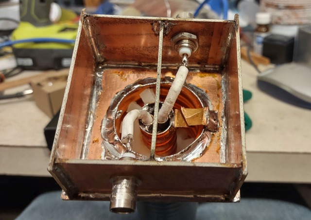 Cavity is often required at a busy site to not only prevent its receiver from being overloaded by off-frequency signals, but also be a good neighbour and prevent low-level signals from your transmitter from getting into other users receivers - not to mention the preventing of those other signal from getting back into your transmitter to generate spurious signals in its own right.
 -
 Presents two distinct hardware modifications for the Icom IC-7300 transceiver, detailing the necessary steps for each. The first modification, a _MARS_ transmit expansion, involves the physical removal of specific surface-mount diodes (D422) from the main board, enabling transmit capabilities across a broader frequency range, including out-of-band frequencies. It specifies the diode location on US versions of the IC-7300 and suggests using small diagonal cutters if a soldering iron is not preferred or available. The second modification focuses on the internal antenna tuner, aiming to provide wider impedance matching capabilities. This involves adding a **100k ohm** resistor to a designated point within the tuner circuit. The resource also briefly mentions a microphone modification for the _HM219_ and a general power increase, though without specific instructions for the latter two. It emphasizes safety precautions, such as disconnecting power and inspecting the work area.
 -
 he LoRa-APRS-iGate was developed in cooperation with the Austrian HAM Radio Association. With this software and the LoRa GW Shield, devices transmitting on LoRa, frequency 433 MHz can be integrated into the APRS network. The transmitter can then be displayed on the website https://aprs.fi.
 -
 A homebrew spectrum analyzer, the Specan, provides a crucial measurement capability often missing from the typical amateur radio shack, allowing for detailed analysis of RF signals up to 70 MHz. This double-conversion superheterodyne receiver design incorporates 112 MHz and 12 MHz intermediate frequencies, utilizing an _Si570_ as the local oscillator for fine tuning down to 1 Hz steps. It offers two resolution bandwidths: 300 KHz for broad spectrum sweeps and 1 KHz for precise close-in distortion measurements, achieving an 80 dB spur-free dynamic range at 1 KHz resolution. The project, a reboot of the classic _W7ZOI/K7TAU_ design from November 1998 QST, integrates an _Arduino_ microcontroller for controlling the Si570, managing a front-panel LCD, and communicating with a PC for spectrum plotting. This approach significantly reduces cost compared to commercial units, making advanced RF diagnostics accessible to homebrewers. The Specan can measure carrier suppression, VFO cleanliness, antenna VSWR, transmitter harmonics, and filter passband shapes, providing insights beyond what an oscilloscope or frequency counter can offer. Construction emphasizes modularity and careful shielding, with each stage built and tested individually on unetched copper clad board. The design includes detailed instructions for integrating the Arduino, building the Si570 oscillator, and aligning the various modules, often using the Specan itself for calibration. It requires a well-regulated linear power supply and can be built with common tools and readily available components, making it a practical and rewarding endeavor for those looking to enhance their RF test bench.
 -
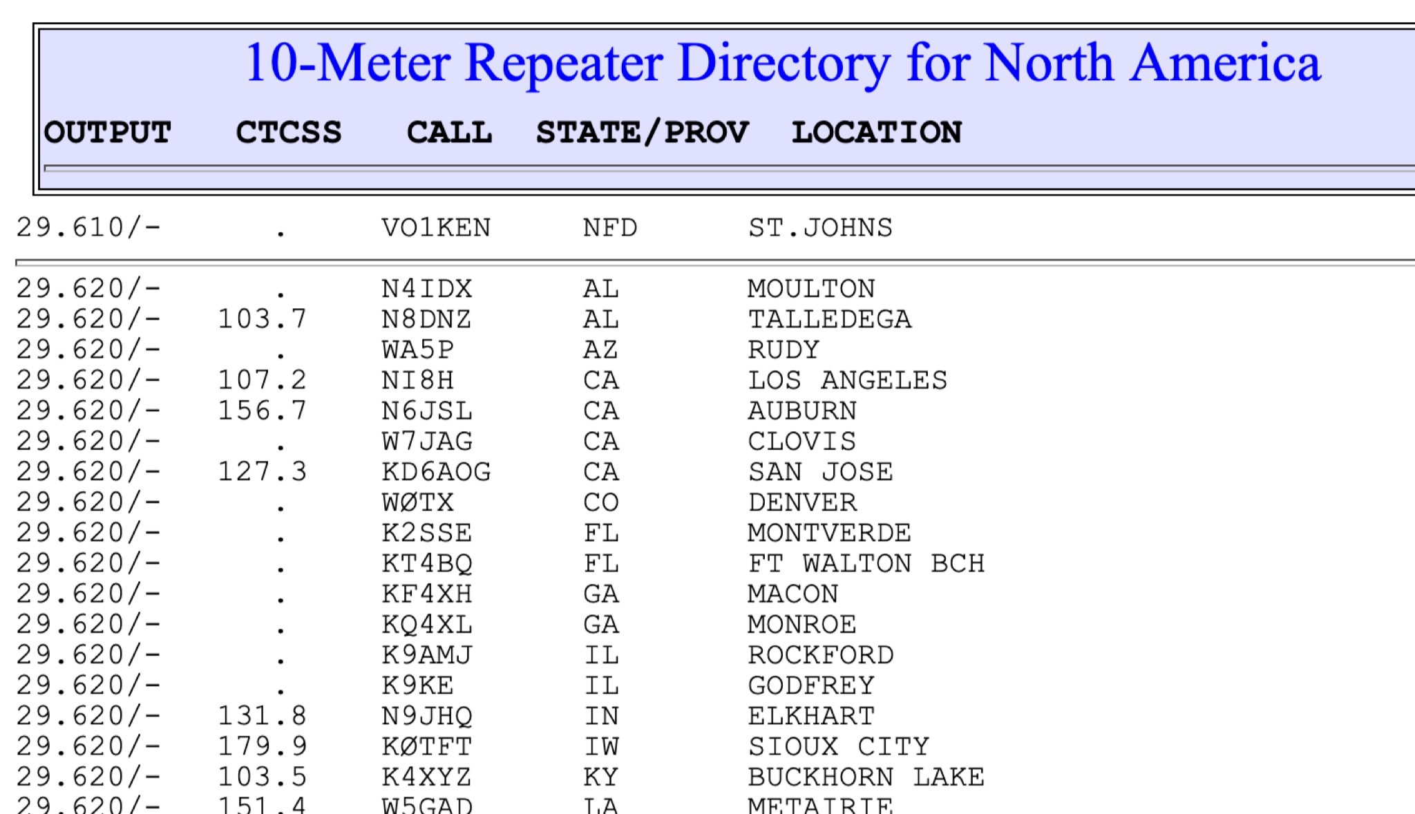 This page show a list of repeaters in north america transmitting from 28 MHz to 29 MHz. The most of them are in the 29.620 to 29.700 frequency range. Some repeaters may be active and on the air while others may not
 -
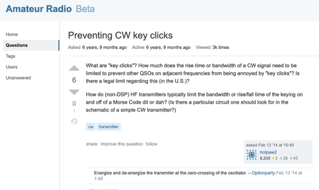 Key clicks are generally undesired clicks or thumps generated by a CW transmitter as the key is put down or let up. How much does the rise time or bandwidth of a CW signal need to be limited to prevent other QSOs on adjacent frequencies from being annoyed by key clicks?
 -
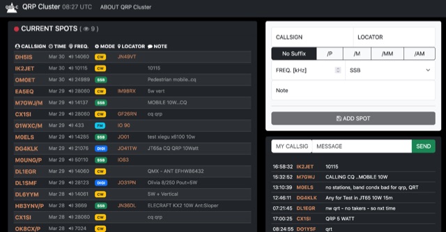 The QRP Cluster provides a dedicated platform for _QRP_ (low power) amateur radio operators to self-spot their on-air activity. This web-based service allows users to post real-time information about their current operating frequency, modulation mode, equipment used, and transmit power. It facilitates QRP-to-QRP contacts and helps other low-power stations locate active QRP signals across various bands. Unlike general DX clusters, the QRP Cluster focuses exclusively on low-power operations, fostering a community for QRP enthusiasts. It enables operators to share details such as **5 watts** or less output, often specifying antenna types or unique portable setups. The platform supports the discovery of QRP stations for casual QSOs, contests, and award hunting, enhancing visibility for stations that might otherwise be overlooked on higher-power clusters.
 -
 The most basic form of repeater receives communication on one frequency and re-transmits it on a different frequency, a process known as duplex communication. This capability significantly extends the range of handheld and mobile radios, as repeaters are typically situated at elevated locations with high-gain antennas and greater transmit power. Repeaters commonly operate with FM modulation on the VHF (30 MHz – 300 MHz) and UHF (300 MHz – 3 GHz) amateur bands, which are ideal for portable and mobile devices. Access to repeaters is often controlled by a CTCSS or PL tone, an inaudible signal that prevents the repeater from retransmitting background noise. This mechanism ensures efficient use of the frequency and prevents illegal continuous transmission. Canadian regulations, for instance, require an Advanced amateur radio license and an available frequency within the band to set up a repeater, each assigned a unique call sign and transmit frequency. Configuring a radio for repeater use involves knowing the repeater's transmit frequency, its receive frequency offset (e.g., -600 KHz for VHF or +5 MHz for UHF), and the necessary CTCSS tone. The article references resources like Repeater Book for locating repeaters and provides practical examples for initiating and concluding a basic repeater session, emphasizing clear identification and concise communication.
 -
 Morsle.fun is a user-friendly web application designed for practicing Morse code reception by guessing transmitted text, which can be either words or call signs. Users can adjust the volume and tone frequency of the Morse code playback. The application tracks performance and generates activity statistics. Call signs are typically more complex than words, containing up to six characters and at least one digit. Users can practice Morse code at speeds ranging from 10 to 60 wpm.
 -
 Learn how to build a simple transmitter called the 'Easy Ten' that can be easily heard at a distance of 10 miles using a random length wire antenna thrown into a tree. This article focuses on working with frequencies in the 3.5 and 7 MHz range without the need for complex setups like coax lines or baluns. The author shares their experience of making contacts across the Pacific Ocean and the United States using just one watt of output power and simple antennas. Discover how to optimize signal output using a homemade level meter made from a DC microameter and a germanium diode.
 -
 Chokes and isolation transformers are essential for receiving antennas to mitigate common mode current, which induces noise and interferes with signal quality. Common mode chokes, formed by winding feedline through ferrite cores, block unwanted current effectively. Proper selection of core material and winding turns ensures resonance near the operating frequency, reducing interference. Isolation transformers further minimize interference, crucial for multi-transmitter stations.
 -
 Addresses the common challenge of constructing effective dual-band antennas for VHF/UHF operations, specifically detailing a J-pole design. It covers the theoretical underpinnings, including calculations for quarter-wavelength radiator and stub sections, accounting for velocity factor and design frequency. The resource provides practical construction guidance using readily available materials like TV twin lead and coaxial cable, culminating in an antenna with a total length of approximately 52 inches. Performance metrics are presented, showing a measured SWR of 1.7:1 or better across most of the 2-meter band and less than 2:1 across the 70-cm band. These SWR measurements, referenced to 50-ohm impedance, were taken at the transmitter end of the feed line. The article also touches upon the necessity of a balun for proper impedance matching between the balanced J-pole and unbalanced coaxial feed line, suggesting a split-core cylindrical ferrite for this purpose.
 -
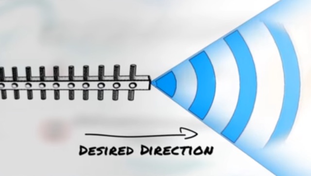 Approximately 3 minutes of video content, originally from _Aruba Networks_, illustrates fundamental principles of antenna gain and radiation patterns. While the source material targets broadband wireless, the underlying physics of RF energy directionality and signal shaping are universally applicable to amateur radio antenna systems across various frequencies. Antenna gain is crucial for maximizing effective radiated power (ERP) without simply increasing transmitter output. The resource explains how elements in a Yagi beam, for instance, absorb and re-radiate RF energy, cumulatively increasing signal amplitude in a desired direction. This process enhances both transmit efficiency and receive sensitivity, directly impacting DX capabilities and overall station performance. Understanding these concepts is paramount for any radio amateur, as the antenna system often represents the most significant factor in a station's operational effectiveness. The article emphasizes that careful calculation and positioning of parasitic elements can dramatically reshape an antenna's radiation pattern, leading to substantial improvements in signal strength and reach.
 -
 Compare the efficiency of two HF (or VHF) antennas by simultaneously transmitting FT8 on nearly the same frequency and analyzing PSKReporter SNR data. Determine the effectiveness of your new antenna compared to the old one in dB, to several decimal places. Run FT8 on two transmitters with different call signs and equal power, connected to each antenna. AntennaCompare analyzes global signal reports, isolating antenna performance.
 -
 Effective suppression of harmonics and parasitic radiation from HF transmitters is crucial, especially with the increasing sensitivity of VHF/UHF radio channels to interference. This project details a hybrid low-pass filter (LPF) designed to operate across the HF bands up to 51 MHz, making it suitable for 6-meter band operations while providing deep VHF/UHF suppression. The design addresses the challenge of modern interference landscapes, where even microvolt-level signals can disrupt wireless sensors and other simple VHF/UHF receivers. The filter utilizes a single elliptic link, combining high cutoff steepness with robust suppression in the hundreds of megahertz range. A key feature is the use of only two standard capacitor values, simplifying construction and component sourcing. The article provides a detailed schematic, performance characteristics, and _RFSim99_ model file, demonstrating a reflection coefficient S11 below 0.017 (VSWR < 1.03) across 1-51 MHz, ensuring minimal degradation to the antenna system. Construction notes include coil winding specifications and capacitor selection guidance, with recommendations for _FR-4_ assembly. Two capacitor sets are presented, with the first variant recommended for its lower RF current demands, keeping currents below 3 A at 1 kW passing power at 51 MHz. Fine-tuning involves adjusting frameless coils, with considerations for capacitor tolerance and high-frequency capacitance measurement accuracy.
 -
 Learn how to enhance your 160 meter reception by building and using a custom band pass filter. Discover how this filter can reduce interference from strong AM broadcast signals, improving the overall performance of your receiver. Find out about the challenges of creating a filter that balances signal loss and attenuation at specific frequencies, and how it can benefit hams operating near powerful transmitters. Whether you're experiencing IMD issues or looking to optimize your 160 meter setup, this article provides practical insights and solutions for ham radio operators.
 -
 KISS703 is a 703 Hz narrowband digital mode for amateur radio, designed for simple, low-power operation without computers. A 500 Hz pilot tone ensures frequency alignment, replaced by unique tones for 37 symbols (letters, numbers, space). Built from common discrete components, it draws about 40 mA at 12 V, ideal for SOTA/IOTA use. The receiver uses amplification, wave shaping, and a pulse-counting frequency meter for manual decoding via a calibrated meter. Transmitter and receiver calibration involves marking meter positions for each tone, enabling fully self-contained messaging with minimal hardware in portable or fixed operations.
 -
 A dual insert microphone design for the Icom IC-7300 transceiver utilizes a **Besson BZ2400 M4 Rocking Armature** insert for frequencies from 500 Hz to 3 kHz, exhibiting a rising response of approximately 11 dB. A generic Electret Condenser insert, powered by the transceiver's microphone line, covers the low-frequency range from 100 Hz to 500 Hz. A Low Pass Filter is incorporated after the Electret insert to prevent frequency overlap, and a pre-set potentiometer (VR1) adjusts the low-frequency response, balancing the output of both inserts. The design emphasizes a "Close Talking" arrangement and addresses audio "colorization" by housing the Besson insert in a thick rubber holder with a foam boot, separate from the circuitry, with the Electret insert also wrapped in a foam boot. Critical importance is placed on using the correct BZ2400 M4 insert with 12 holes in its face plate. The frequency response table for the BZ2400 M4 insert shows 0 dB at 500 Hz, rising to +11 dB at 3000 Hz, while the Electret insert with the Low Pass Filter provides 0 dB at 100 Hz, rolling off to -9 dB at 500 Hz and -50 dB at 3000 Hz. This combination ensures a broad, balanced audio spectrum for SSB operation. The project includes a circuit diagram, a comprehensive parts list detailing components like a 1 Henry iron-cored inductor (L1) and various capacitors, and a board layout within the metal tube. The completed unit provides a tailored audio profile for the IC-7300, enhancing transmit audio quality.
 -
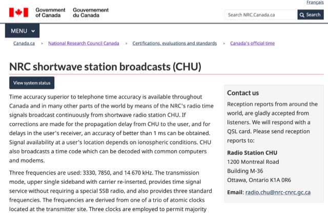 CHU is a time signal transmitter operated by the National Research Council in Canada. It broadcasts on various frequencies and is primarily used for time synchronization in North America.
 -
 The project details the construction of a GM3OXX OXO transmitter, designed to accommodate **FT-243 crystals** using 3D-printed FX-243 holders from John KC9ON. It presents specific frequency adjustments, noting a 7030 KHz HC-49/s crystal could be tuned from 7029.8 KHz to 7031.7 KHz with an internal 45pF trimmer capacitor. The build incorporates a modified keying circuit to prevent oscillator run-on key-up and includes a TX/RX switch for sidetone via a connected receiver, with the transmitter output routed to a dummy load on receive. Practical construction aspects are thoroughly covered, including the process of cutting a rectangular opening in a diecast enclosure for the FT-243 socket and the selection of a **low-pass filter** (LPF) based on the QRP Labs kit, derived from the W3NQN design. The author achieved approximately 800mW output power from a 14.75V supply, measured with an NM0S QRPoMeter, using a 16.5-ohm emitter resistor in the 2N3866 final stage. The article also touches upon the potential for frequency agility across the 40M band using multiple FX-243 units with various crystals. The narrative includes a brief diversion into Bob W3BBO's recent homebrew projects, such as his Ugly Weekender MK II transceiver, highlighting the enduring appeal of classic QRP designs. The author reflects on the personal satisfaction derived from building RF-generating equipment, irrespective of DX achievements, and shares experiences of making local contacts with the 800mW OXO transmitter on 40 meters.
 -
 The article discusses the construction of a UHF band-stop stub filter to protect an APRS receiver from potential damage during a balloon launch. The author, who communicates using a 441 MHz transmitter, needed to ensure that the RTL-SDR dongle receiving at 144 MHz wouldn't be damaged by the transmissions. The solution involved creating a quarter-wavelength open stub filter using coaxial cable, which attenuates the 441 MHz signal while allowing the 144 MHz signal to pass through. The filter's design is based on the principles of constructive and destructive interference, with careful measurement and trimming to achieve the desired frequency response. The final filter provided 34.8 dB of insertion loss at 441 MHz and minimal loss at 144 MHz, effectively protecting the receiver.